2 layers76 × 74 mm
Aurduino Autopilot Kicad - Simplified
maunope/solariUdineAutoPilotArduino
An Arduino based Solari Udine clock driver handling DST and catch up after power loss
26 parts
 maunope/solariUdineAutoPilotArduino
An Arduino based Solari Udine clock driver handling DST and catch up after power loss
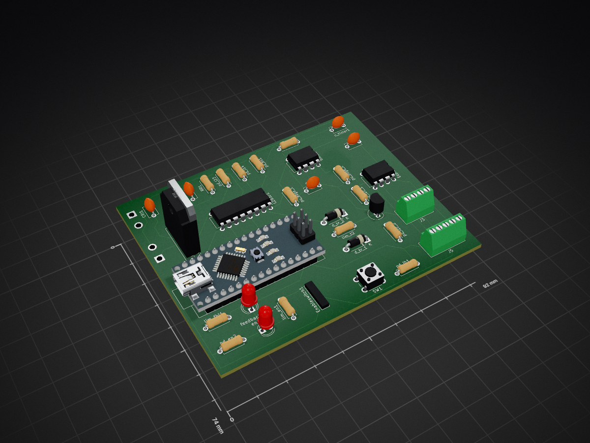
Arduino Autopilot is an open-source printed circuit board by maunope, from the maunope/solariUdineAutoPilotArduino repository on GitHub. It is a 2-layer board of 92 × 74 mm with 36 parts on 43 nets, routed with 257 tracks and 0 vias.
It is built around the L293D, CAT24C256LI and S8050. Its parts include 4 connectors, 2 capacitors, 1 IC, 1 switch and 1 inductor. It belongs with the lEDs and displays boards and the AVR (ATmega, ATtiny) boards of this library.


I'm stopping development on this board, I'll build a new, ESP32 based one with the following goals:
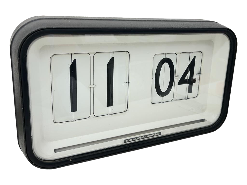
This is still a prototype. The circuit design was built and tested on a perfboard; the KiCad board design was never tested. Use at your own risk and please don't come whining if you damage your flip clock or set your house on fire.
Arduino-based Solari Udine clock controller, suitable for alternating-pulse Solari Udine clock motors (i.e. Cifra 12). Controls hours and minutes; no calendar functions are provided. The current board design accepts a single Vcc in, either 12V or 24V, from an external power source.
Main features:
An LED provides visual feedback; an optional LCD1602 display can be plugged in to show the status.
The software tries to mitigate strain on the flip clock by limiting the number and frequency of roller turns:
The following features improve durability and operation:
WORK IN PROGRESS: Check the schematic in this repo. I've built and tested it on perfboard; the board design might not be 100% correct, and the layout could definitely use some improvement.
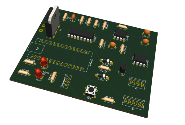
The "Simplified" board version uses some 30% fewer components by removing the following features:
Considering how unlikely it is for the sketch to remain stuck with motor output set high, you might want to save yourself some hassle, especially if you're building on perfboard.
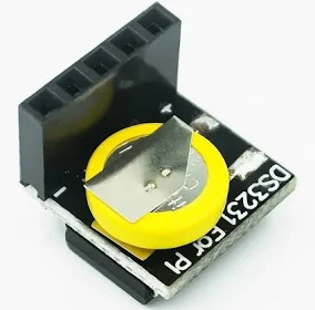
I've built the board using these cheap DS3231 modules bought off Amazon. The design uses a male connector matching their Vcc-signal-signal-NC-Ground pinout; you might want to use something different and change the board design accordingly. One good thing about these is that they're small enough and can be easily swapped out for testing and debugging.
How to read led signals
Either for good or bad news, the green LED will flash. The red LED will stay on when the general enable switch is on.
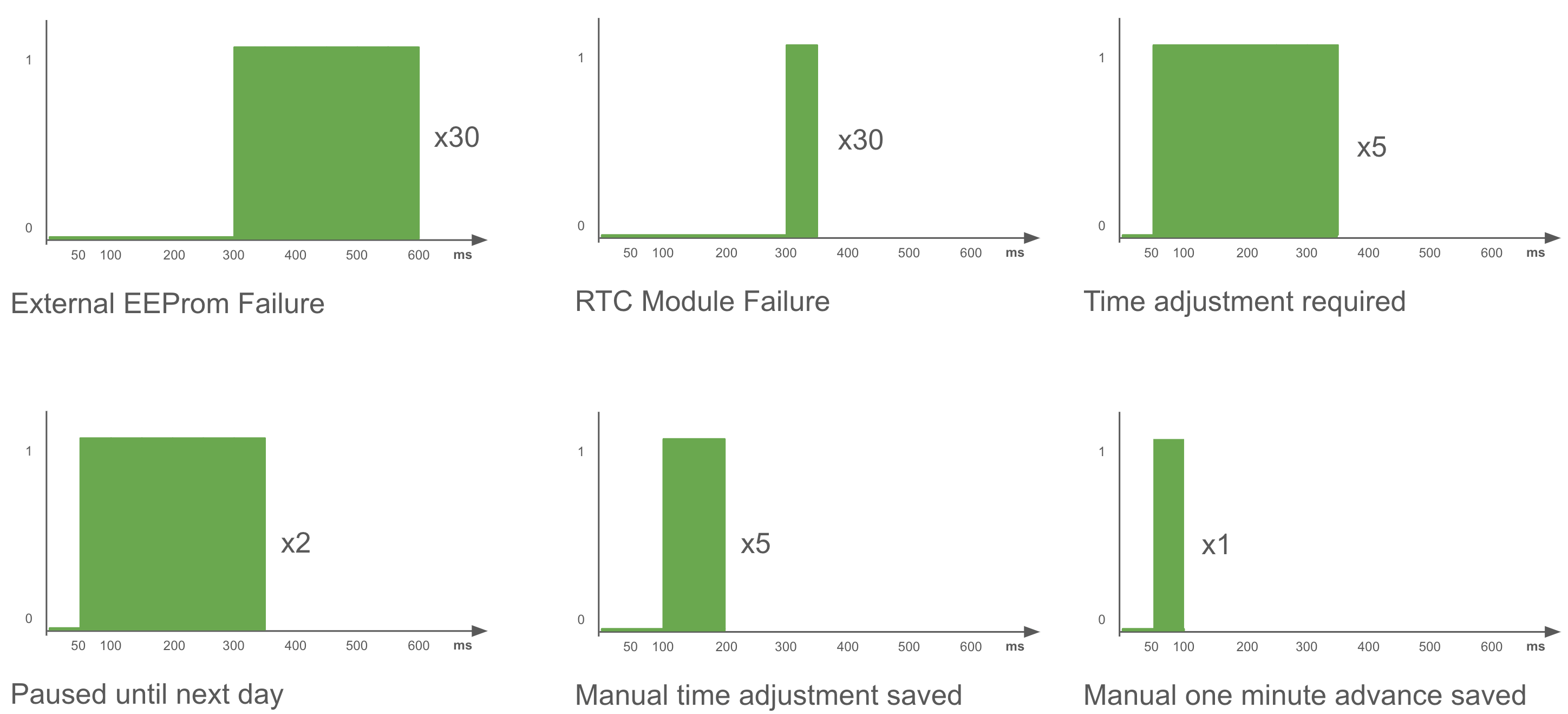
First things first: let's not fry stuff.
SET_COMPILE_TIME_TO_RTC flag turned on, or use serial commands to prime the RTC module.The controller will now keep the flip clock display aligned with the internal RTC clock.
A switch allows pausing motor movement for maintenance and dialing in commands; the clock will catch up automatically once enabled again. An LED will remain ON while movement is paused. The switch also disables deep sleep time and prepares the Arduino for accepting commands: wait until the feedback LED blinks once after pausing movement, then use the push button or serial commands.
Important: Only use push button commands with the motor enable switch turned off.
Important: Only issue serial commands with the motor enable switch turned off.
Commands format: (<<|>>)[A-Z]{1,10}[a-z,A-Z,0-9]{1,20}
One command per line, max 32 chars long. The parser is pretty crude, please stick to tested commands ;-)
Available commands:
DEBUG_MODE enables serial port and LCD debug messages, disables sleep time, and forces reinitialization of the EEPROM and RTC module on each read.SET_COMPILE_TIME_TO_RTC forces writing the sketch build time to the RTC on each boot. Only use this to program new RTC modules.Q: Instead of catching up, the clock is standing still and the "Paused until next day" pattern flashes.
A: When more than 120 minutes need to be caught up, the automatic adjustment will pause and wait for the clock time to be correct again the next day.
Q: The Arduino keeps resetting every half a minute or so, the feedback led flashes
A: Either the EEPROM or RTC module isn't responding; the board needs fixing.
Q: I've hooked up a display, now what?
A: Note that the display only works when DEBUG_MODE flag is raised
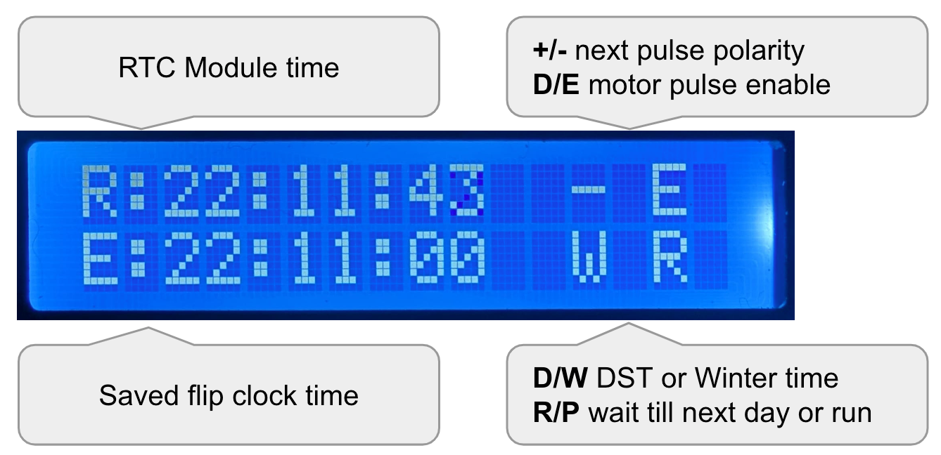
Q: How can I tell if my eeprom is corrupted or simply requires initialization?
A: "Adj. time" on the display or "No valid time set in eeprom, please adjust clock" on the Serial are good news.
Q: My RTC module lost its time configuration!
A: >>DATETIME[0-9]+ command should fix it, however, if it happens again, the module batttery might be drained
Q: I can't tell what's going on with eeprom data
A: The <<EEPROMDATA command extracts all the info saved on the EEPROM.
Q: LCD doesn't display anything, and/or serial messages are missing
A: Set the DEBUG_MODE build flag and upload the firmware again.
Q: (serial|button) commands are not working!
A: They only work reliably when motor movement is paused (solid red LED). During regular operation, the Arduino is awake and responding to commands for only a few seconds per minute. Good luck catching it awake! :-)
Q: My clock drifts X seconds ahead/behind every day
A: Buy a proper RTC module next time! :-) There's a handy feature to correct this if the drift is the same every day; see serial commands.
Q: My clock drifts X minutes ahead/behind every day
A: Yikes! That's not OK! Try a different RTC module, then check your board for errors on the I2C bus pullup resistors and +5V power. I've tested the board design by powering I2C devices straight from a voltage regulator, bypassing the Arduino's internal one. Either do the same, or dig into the sleep configurations to figure out how to keep the RTC powered during sleep. If you figure something out, open a PR here :-)
Q: I got an RTC failure message/blink and then the board rebooted
A: Your RTC went nuts! It happens every now and then with cheap *ss modules; my MTBF is around 4 months. The sketch tries its best to recover to the last timestamp that made sense if it detects the RTC is acting up.
Q: No matter what I do, the clock keeps flipping!
A: The RTC module is returning wrong timestamps, and the checks I've put in place are not working. :-( Compile the sketch in debug mode, use serial commands to check what timestamp is recorded in the RTC module, and fix it. Realign the EEPROM time with the RTC time, reboot, and check after a few minutes that the RTC module is behaving. If you wish, drop me an email about the problem including the timestamp you had in the RTC module and the one in your EEPROM (or, even better, figure out what's wrong and open a PR :-) ).
Q: That PCB design is lame!
A: It is. Any help is much appreciated! ;-)
| Qty | Value | Footprint | References |
|---|---|---|---|
| 12 | R | Resistor_THT:R_Axial_DIN0207_L6.3mm_D2.5mm_P7.62mm_Horizontal | lim_en1, lim_fbl1, lim_t2, pd_en1, pd_en2, pd_i14, pd_i23, pd_ib1, pu_edge_1, pu_edge_2, pu_i2c_1, pu_i2c_2 |
| 2 | D | Diode_THT:D_DO-41_SOD81_P7.62mm_Horizontal | d_tr_1, d_tr_2 |
| 2 | LED | LED_THT:LED_D4.0mm | en_led1, feedback_led1 |
| 1 | 0.1uf | Capacitor_THT:C_Disc_D5.1mm_W3.2mm_P5.00mm | CRI1 |
| 1 | 100k | Resistor_THT:R_Axial_DIN0207_L6.3mm_D2.5mm_P7.62mm_Horizontal | r_timer1 |
| 1 | 10uF | Capacitor_THT:C_Disc_D5.1mm_W3.2mm_P5.00mm | CRO1 |
| 1 | 12V_in | Connector_Wire:SolderWire-1sqmm_1x02_P5.4mm_D1.4mm_OD2.7mm | J1 |
| 1 | 1k | Resistor_THT:R_Axial_DIN0207_L6.3mm_D2.5mm_P7.62mm_Horizontal | RR1 |
| 1 | 330 | Resistor_THT:R_Axial_DIN0207_L6.3mm_D2.5mm_P7.62mm_Horizontal | RR2 |
| 1 | Arduino_Nano_v3.x | Module:Arduino_Nano | Arduino1 |
| 1 | CAT24C256 | Package_DIP:DIP-8_W7.62mm | Eeprom1 |
| 1 | C_Small | Capacitor_THT:C_Disc_D5.1mm_W3.2mm_P5.00mm | c_timer1 |
| 1 | ICM7555xP | Package_DIP:DIP-8_W7.62mm | timer1 |
| 1 | L293D | Package_DIP:DIP-16_W7.62mm | L293D1 |
| 1 | LM350_TO3 | Package_TO_SOT_THT:TO-3PB-3_Vertical | U1 |
| 1 | S8050 | Package_TO_SOT_THT:TO-92_Inline | tr_2 |
| 1 | SW_Push | Button_Switch_THT:SW_PUSH_6mm | SW1 |
| 1 | c_edge | Capacitor_THT:C_Disc_D5.1mm_W3.2mm_P5.00mm | C2 |
| 1 | c_filt | Capacitor_THT:C_Disc_D5.1mm_W3.2mm_P5.00mm | C1 |
| 1 | to_LCD | TerminalBlock:TerminalBlock_Xinya_XY308-2.54-4P_1x04_P2.54mm_Horizontal | J3 |
| 1 | to_RTC | TerminalBlock:TerminalBlock_Xinya_XY308-2.54-5P_1x05_P2.54mm_Horizontal | J5 |
| 1 | to_clock | Connector_Wire:SolderWire-1sqmm_1x02_P5.4mm_D1.4mm_OD2.7mm | J2 |
| 1 | ~ | Button_Switch_THT:SW_Slide-03_Wuerth-WS-SLTV_10x2.5x6.4_P2.54mm | Enableswitch1 |
maunope/solariUdineAutoPilotArduino
An Arduino based Solari Udine clock driver handling DST and catch up after power loss


eamars/RaspberryPi-Pico-Motor-Expansion-Board
A raspberry pi pico expansion board designed for OpenTrickler project

nullstalgia/NullWiiCon
AVR Firmware to convert Nintendo Extension port controllers to USB for use on Switch and PC

bmo/tuning-knob-pcboard
KiCAD PC Board design for a tuning knob that works with Flex Radio SmartSDR, PowerSDR, and RHR. Uses STM32 hardware.
It measures 92 × 74 mm and has 2 copper layers, 1.6 mm thick.
36 parts, built around the L293D, CAT24C256LI and S8050. The full list of its parts is on this page, with links to each part's symbol and footprint where PCBKit's library has them.
From the maunope/solariUdineAutoPilotArduino repository on GitHub, at the commit this page was made from: the board is Arduino Autopilot Kicad/Arduino Autopilot.kicad_pcb and its schematic Arduino Autopilot Kicad/Arduino Autopilot.kicad_sch. PCBKit opens the board in the browser, with nothing to install.
Its repository states no licence, so its author keeps all rights: ask maunope before reusing the design.