
4 layers200 × 60 mm

Knockoffs of old Marantz stereos
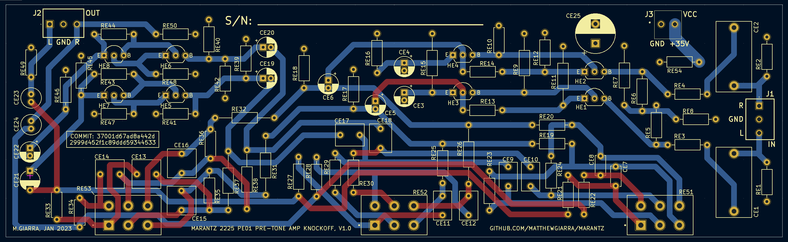
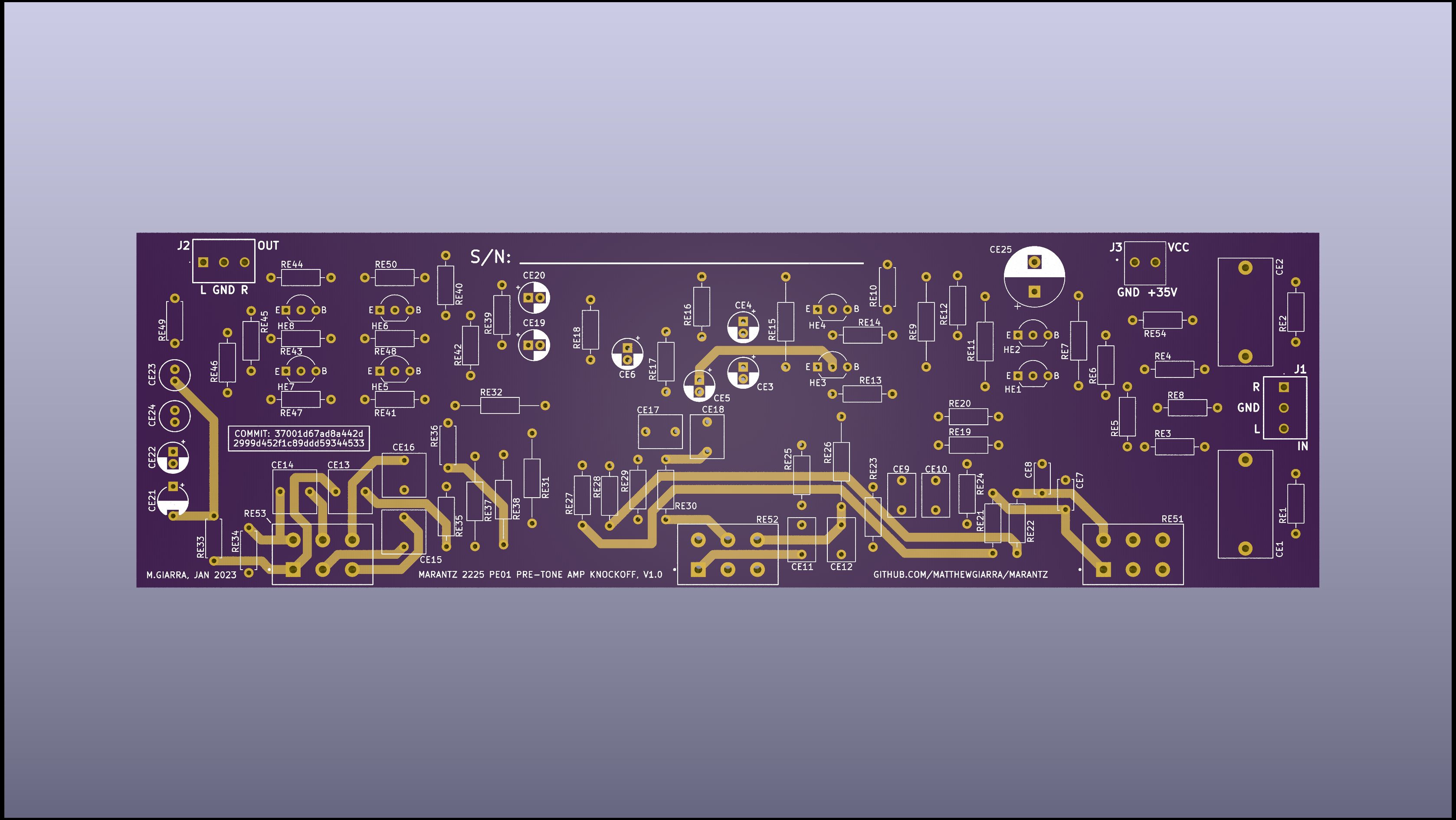
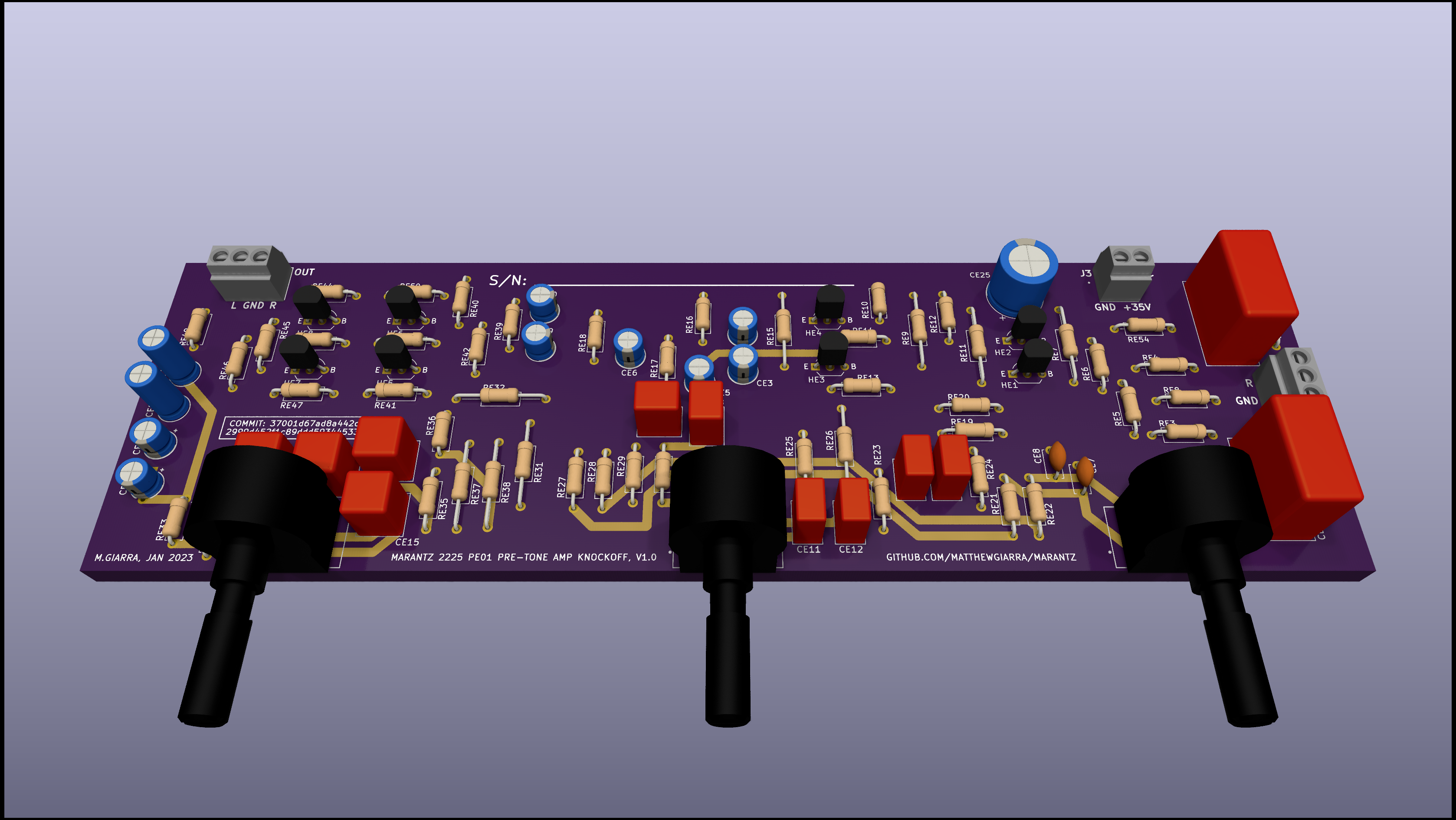
P800 is an open-source printed circuit board by matthewgiarra, from the matthewgiarra/marantz repository on GitHub. It is a 4-layer board of 72 × 84 mm with 30 parts on 14 nets, routed with 137 tracks and 2 vias.
It is built around the KSC2383YTA, MBRF10150CT and MBRF10150CTR, with the TIP41C among its other parts. Its parts include 10 capacitors, 7 resistors, 6 connectors and 1 fuse.


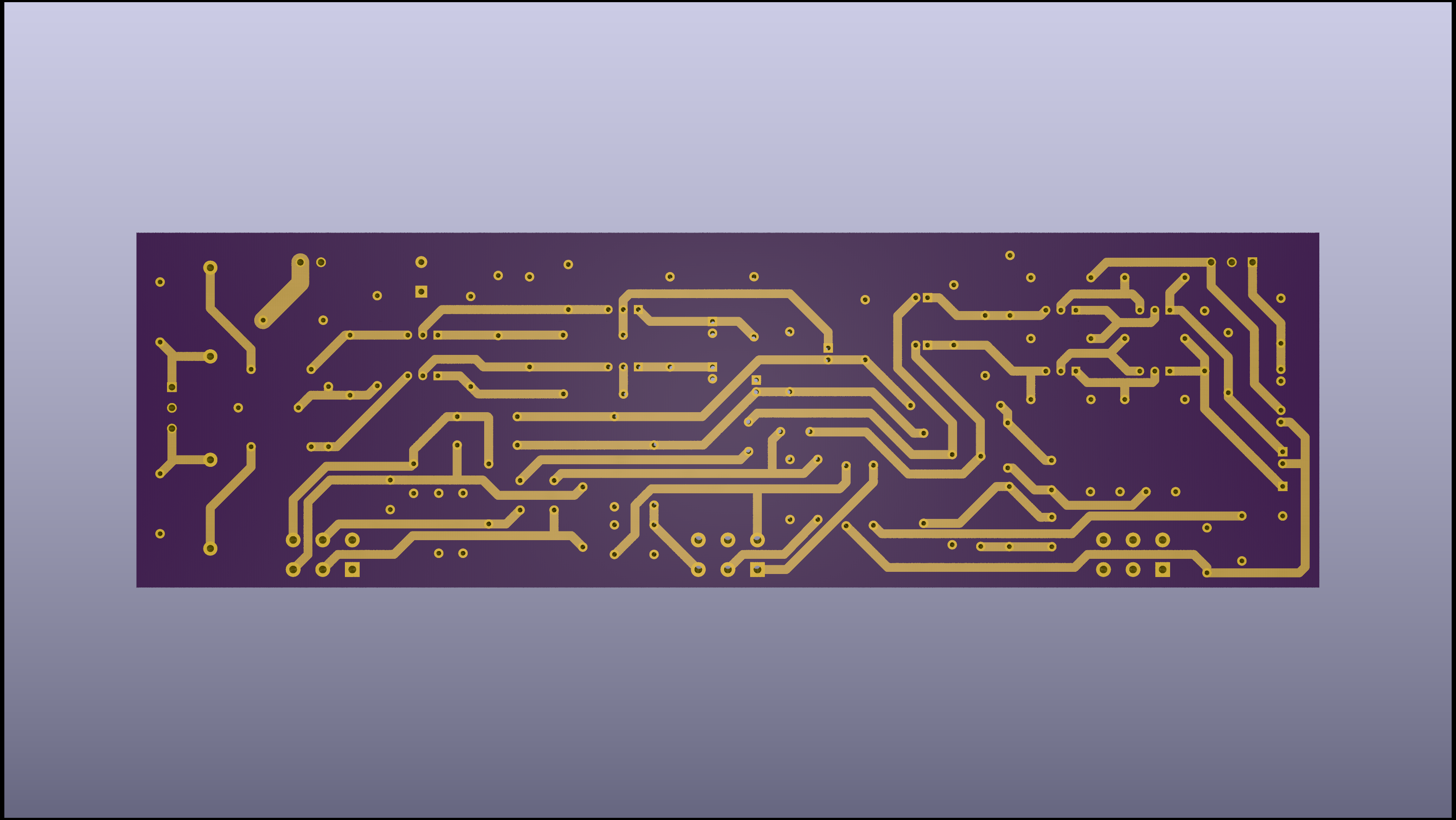
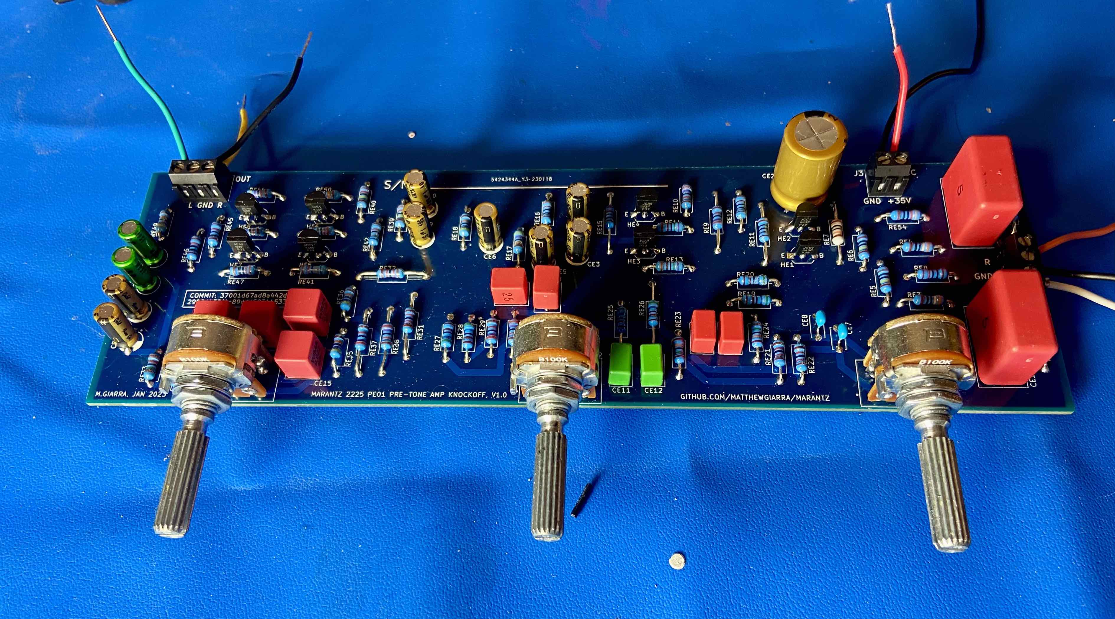
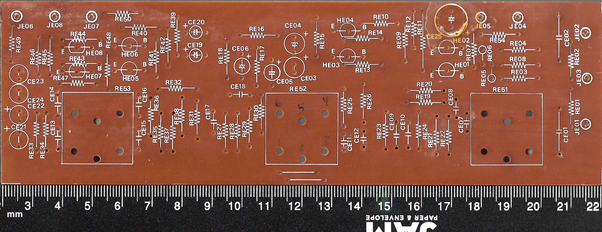
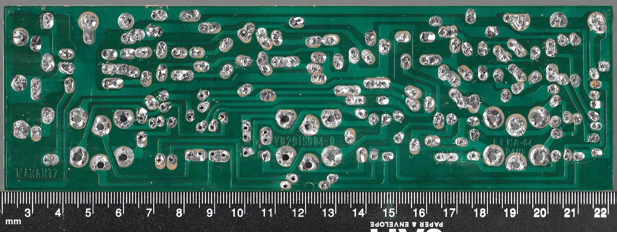
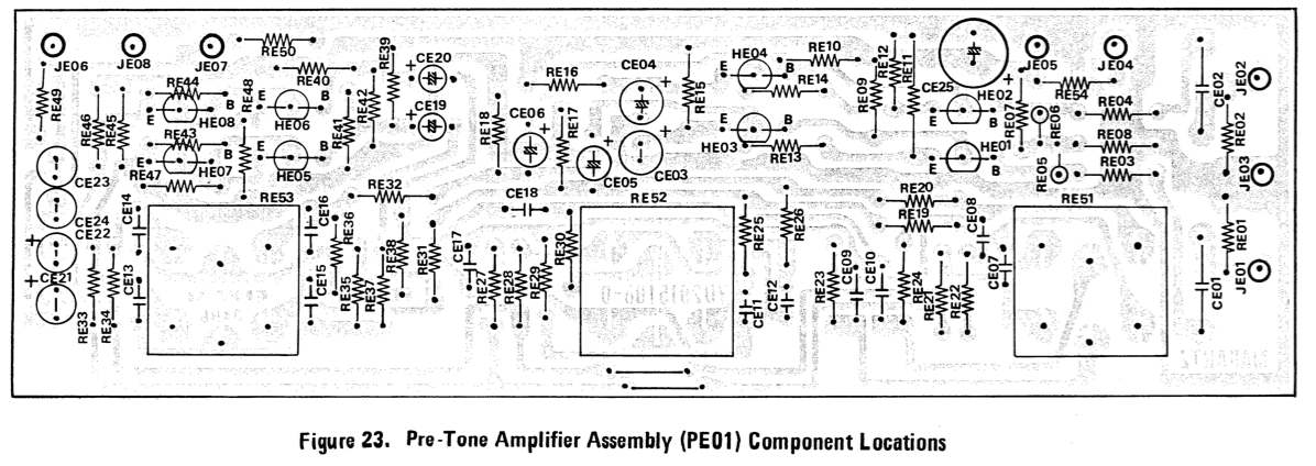
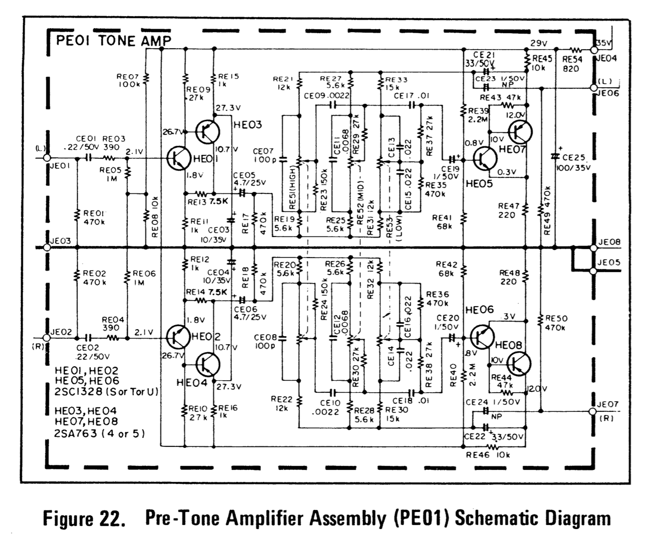
This project recreates (i.e., knocks off) the Marantz 2225 pre-tone amplifier (PE-01), as specified in the Marantz 2225L service manual, using modern and readily-available components. Our custom board is designed to function as a drop-in replacement for the original device. We selected components that meet or exceed the specifications from the service manual, which were experimentally verified by measuring values of components sourced from a vintage PE-01. When discrepancies were discovered between the service manual's component specifications and physical measurements of vintage components, we prioritized the physical measurements. The PCB layout was modified as necessary to accommodate the physical dimensions of our chosen components, and uses a four-layer PCB rather than the single layer of the original product. We used KiCad for design, and validated functionality via SPICE simulation prior to manufacturing. Quantitative characterization of the physical prototype is still in progress, but the initial subjective impression is that it sounds pretty good.
The bill of materials/components list is here.
| Qty | Value | Footprint | References |
|---|---|---|---|
| 3 | Conn_01x01 | P800_footprint_library:Metz_Connect_1pos_terminal_360291 | J4, J5, J6 |
| 2 | 1.5k | Resistor_SMD:R_1206_3216Metric_Pad1.30x1.75mm_HandSolder | R803, R804 |
| 2 | 470u | Capacitor_THT:CP_Radial_D12.5mm_P5.00mm | C803, C804 |
| 2 | 6800u | Capacitor_THT:CP_Radial_D25.0mm_P10.00mm_SnapIn | C002, C003 |
| 2 | Conn_01x04 | P800_footprint_library:molex_nanofit_4-pos_header_vert_1053091204 | J1, J2 |
| 1 | 0.01u | P800_footprint_library:cap_ceramic_RDER72H103K1M1H03A | C802 |
| 1 | 0.047u | Capacitor_THT:C_Rect_L13.0mm_W5.0mm_P10.00mm_FKS3_FKP3_MKS4 | C806 |
| 1 | 0.04u | P800_footprint_library:cap_ceramic_RCER71H473K0M1H03A | C807 |
| 1 | 100u | Capacitor_THT:CP_Radial_D10.0mm_P5.00mm | C805 |
| 1 | 1N4744 | Diode_THT:D_DO-41_SOD81_P10.16mm_Horizontal | H807 |
| 1 | 22 | Resistor_SMD:R_2512_6332Metric_Pad1.40x3.35mm_HandSolder | R801 |
| 1 | 3.3u | Capacitor_THT:CP_Radial_D5.0mm_P2.00mm | C808 |
| 1 | 330 | Resistor_SMD:R_2512_6332Metric_Pad1.40x3.35mm_HandSolder | R805 |
| 1 | 36k | Resistor_SMD:R_1206_3216Metric_Pad1.30x1.75mm_HandSolder | R807 |
| 1 | 39k | Resistor_SMD:R_1206_3216Metric_Pad1.30x1.75mm_HandSolder | R806 |
| 1 | 470u | Capacitor_THT:C_Radial_D10.0mm_H20.0mm_P5.00mm | C809 |
| 1 | Conn_01x02 | P800_footprint_library:molex_nanofit_2-pos_header_vert_1053091302 | J3 |
| 1 | Fuse 1A 250V | P800_footprint_library:fuse_holder_0PTF0078P | F1 |
| 1 | Heatsink | P800_footprint_library:heatsink_577202B00000G | HS1 |
| 1 | KSC2383 | Package_TO_SOT_THT:TO-92_Wide | H806 |
| 1 | MBRF10150CT | Package_TO_SOT_THT:TO-220-3_Vertical | H804 |
| 1 | MBRF10150CTR | Package_TO_SOT_THT:TO-220-3_Vertical | H803 |
| 1 | TIP41C | Package_TO_SOT_THT:TO-220-3_Vertical | H805 |
| 1 | TRIMPOT 5K | P800_footprint_library:pot_3386F-1-502LF | R808 |

profdc9/FlexibleCharger
An Arduino-controlled charger for different kinds of batteries, or it can be a standalone power supply


eGuardianDev/atmegaStepperDriver
Open source stepper driver powered by atmega328p chip. First prototype designed for used in 3D printer.


BojanSof/Lab-Bench-PSU
Laboratory bench power supply with switching preregulator and LDO.

DeniseViltes/dce-g5-proyecto_integrador
FIUBA - Electrónica - Taller de Diseño de Circuitos Electrónicos -Proyecto de diseño: Sistema de alimentación para aplicaciones industriales y automotrices

azzamjhd/PID-position
kendali otomatis 2 - project PID control position for an arm with propeller

bluesyann/tripico-psu
3-Channels Raspberry Pico-based smart power supply. Can run as standalone power supply (V or I controlled), run I-V sweeps decribed in yaml files, or run as a passive ammeter/voltmeter
It measures 72 × 84 mm and has 4 copper layers, 1.6 mm thick.
30 parts, built around the KSC2383YTA, MBRF10150CT, MBRF10150CTR and TIP41C. The full list of its parts is on this page, with links to each part's symbol and footprint where PCBKit's library has them.
From the matthewgiarra/marantz repository on GitHub, at the commit this page was made from: the board is 2225/P800/P800.kicad_pcb and its schematic 2225/2225/2225.kicad_sch. PCBKit opens the board in the browser, with nothing to install.
Its repository states no licence, so its author keeps all rights: ask matthewgiarra before reusing the design.