

4 layers72 × 84 mm

 matthewgiarra/marantz
Knockoffs of old Marantz stereos
2225 PE01 is an open-source printed circuit board by matthewgiarra, from the matthewgiarra/marantz repository on GitHub. It is a 4-layer board of 200 × 60 mm with 90 parts on 54 nets, routed with 317 tracks and 0 vias.
It is built around the KSA992FTA and KSC1845FTA.
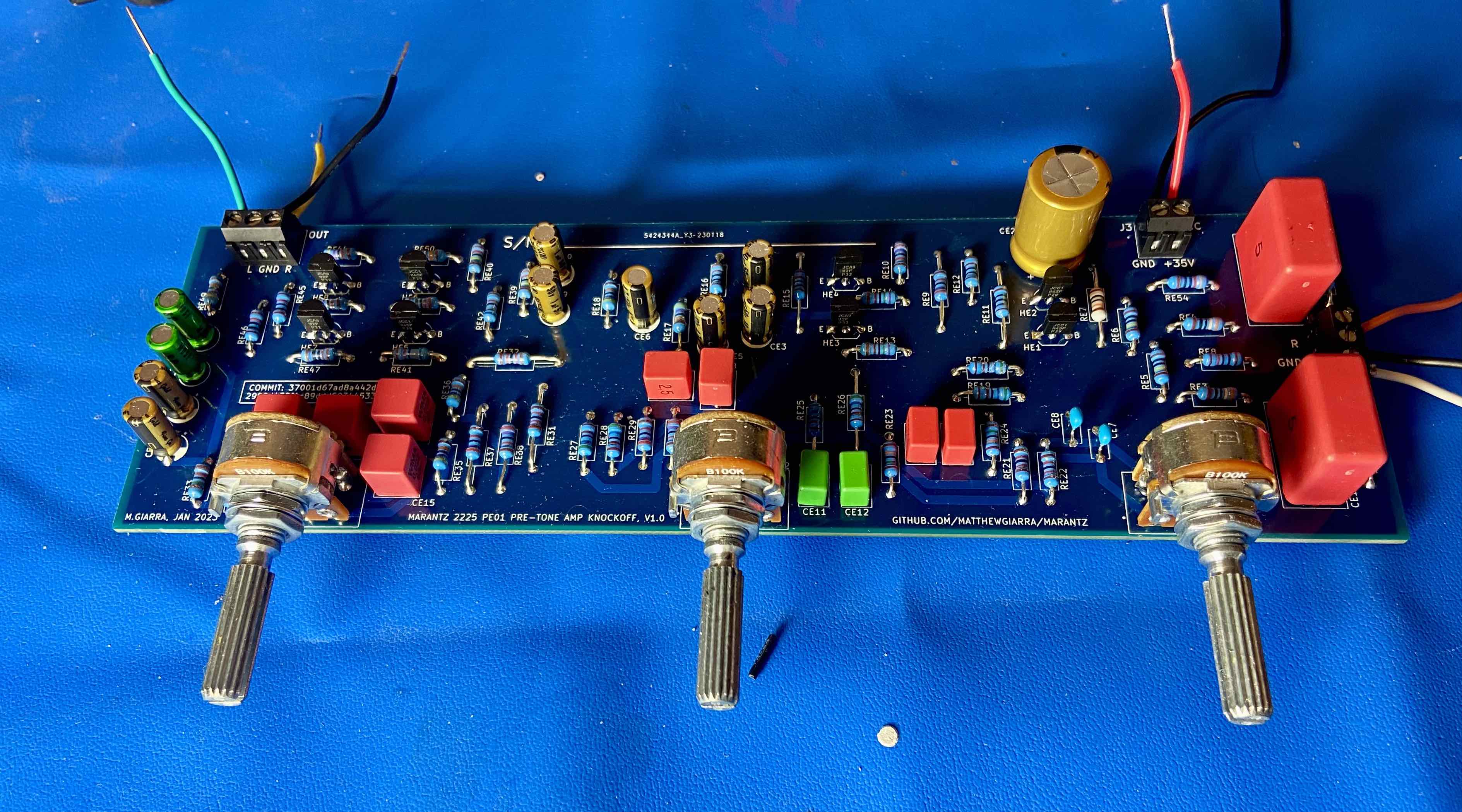
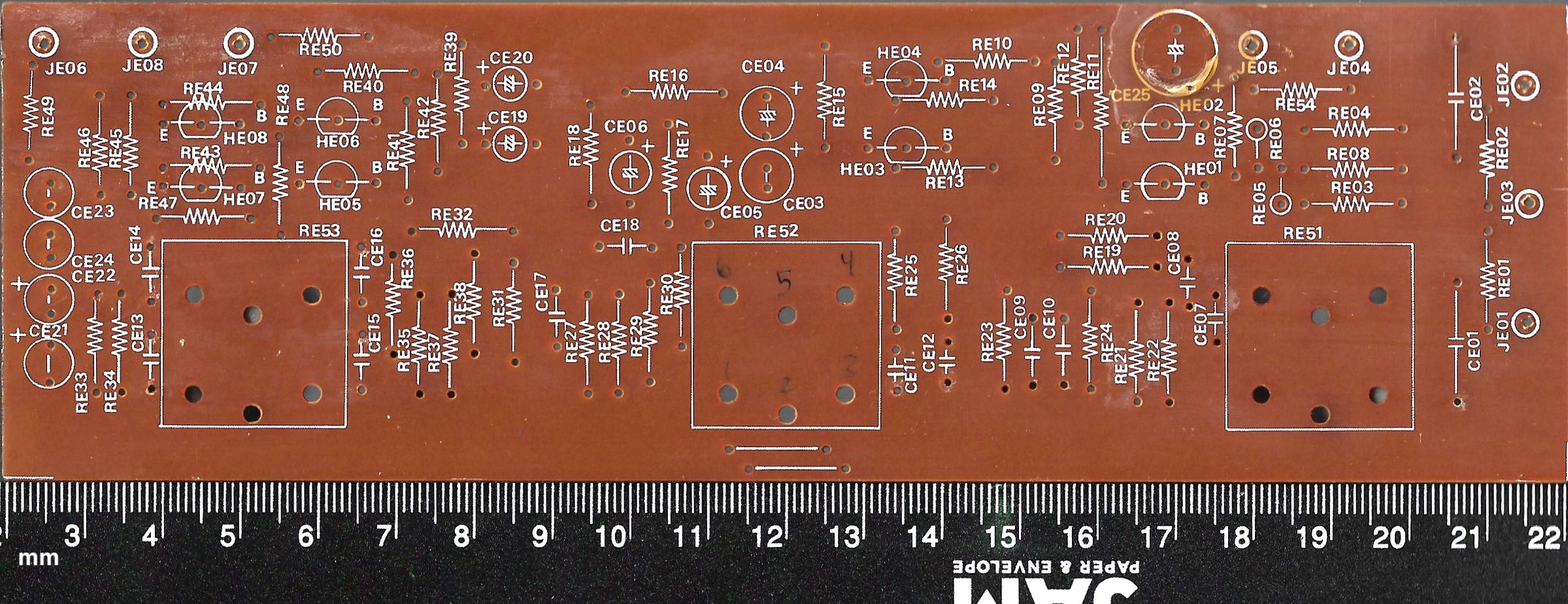
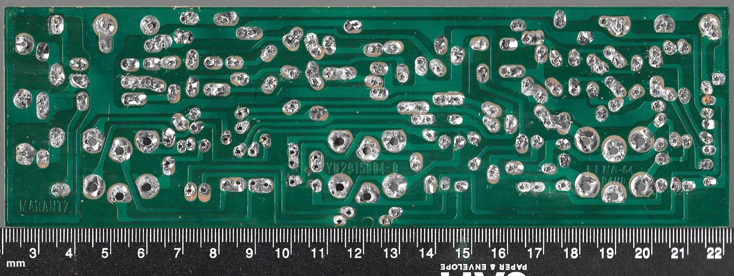
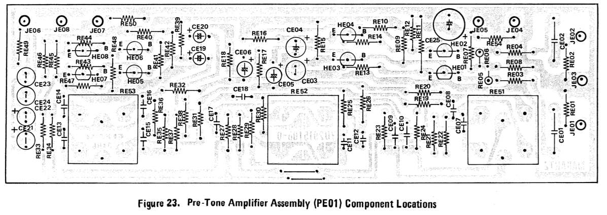
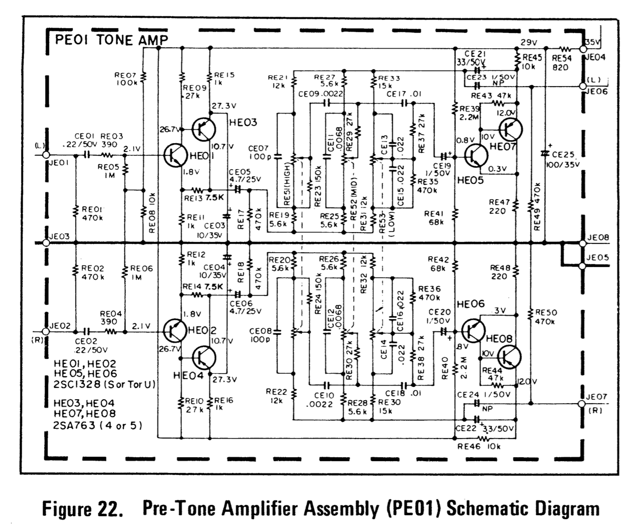
This project recreates (i.e., knocks off) the Marantz 2225 pre-tone amplifier (PE-01), as specified in the Marantz 2225L service manual, using modern and readily-available components. Our custom board is designed to function as a drop-in replacement for the original device. We selected components that meet or exceed the specifications from the service manual, which were experimentally verified by measuring values of components sourced from a vintage PE-01. When discrepancies were discovered between the service manual's component specifications and physical measurements of vintage components, we prioritized the physical measurements. The PCB layout was modified as necessary to accommodate the physical dimensions of our chosen components, and uses a four-layer PCB rather than the single layer of the original product. We used KiCad for design, and validated functionality via SPICE simulation prior to manufacturing. Quantitative characterization of the physical prototype is still in progress, but the initial subjective impression is that it sounds pretty good.
The bill of materials/components list is here.
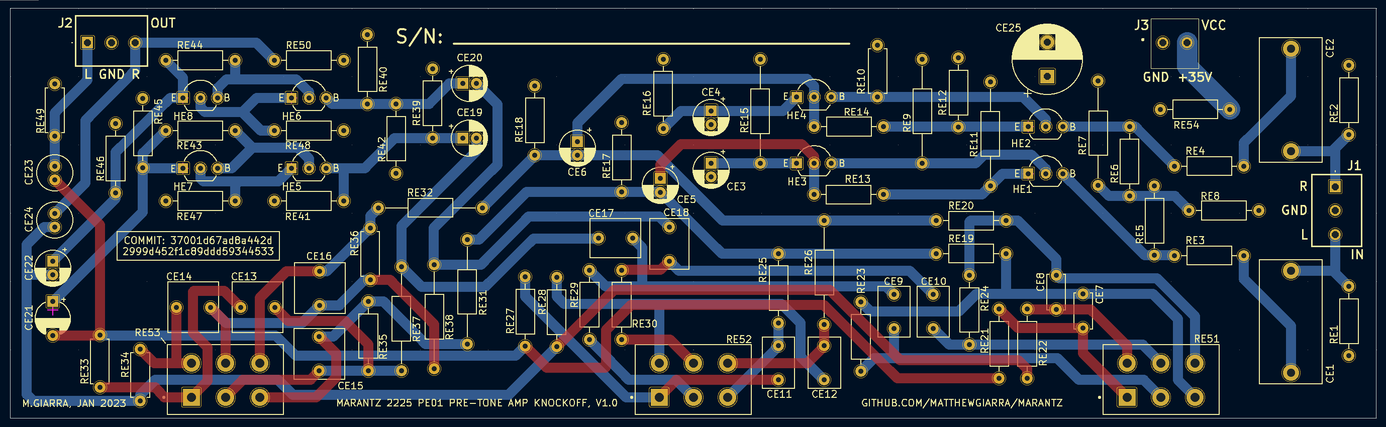
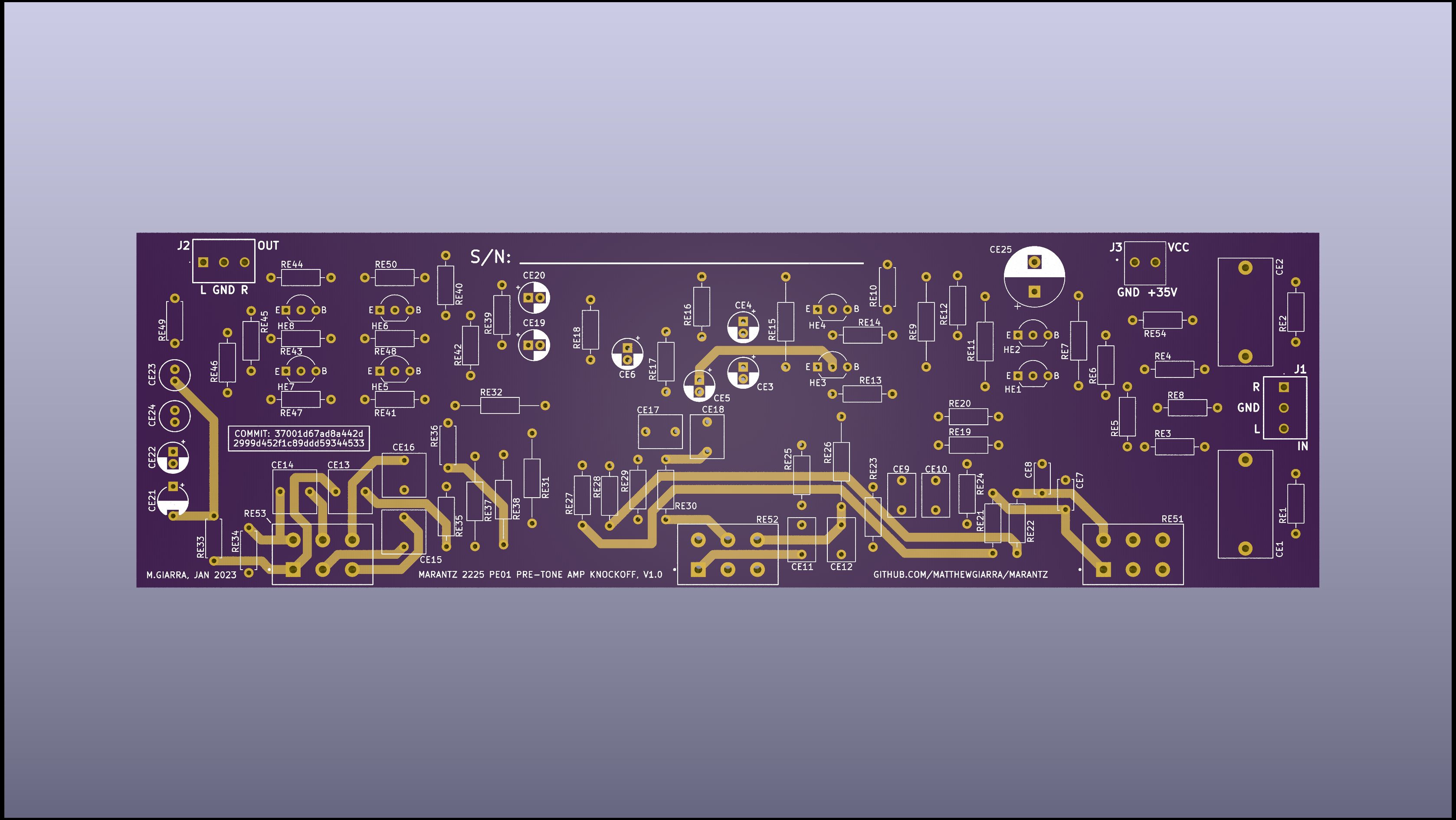
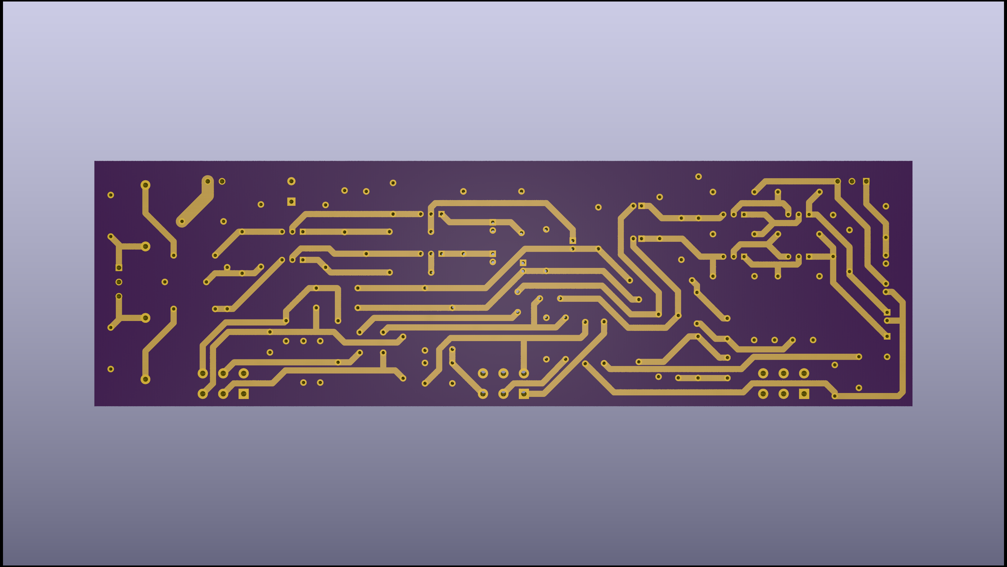
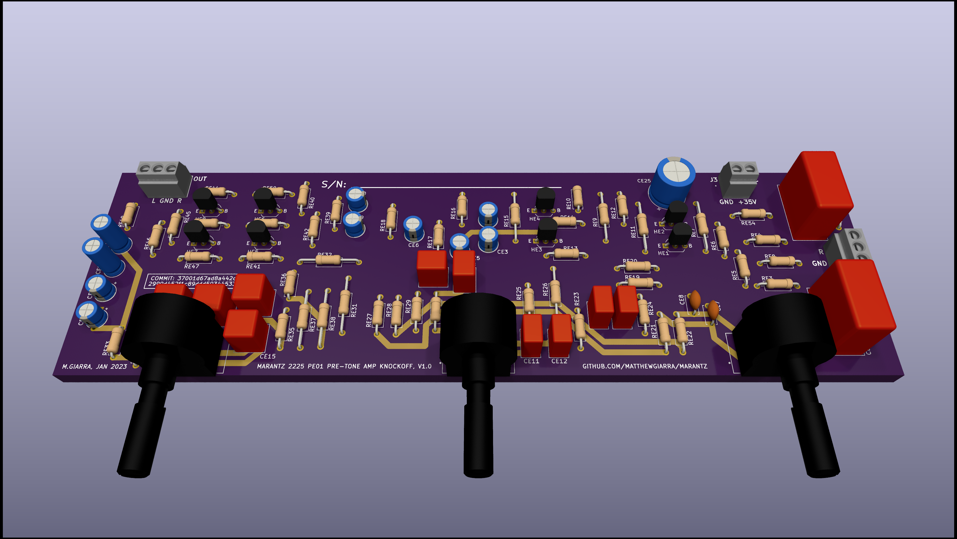
| Qty | Value | Footprint | References |
|---|---|---|---|
| 6 | 470k | Resistor_THT:R_Axial_DIN0207_L6.3mm_D2.5mm_P10.16mm_Horizontal | RE1, RE2, RE17, RE18, RE35, RE50 |
| 5 | 5.6k | Resistor_THT:R_Axial_DIN0207_L6.3mm_D2.5mm_P10.16mm_Horizontal | RE19, RE20, RE25, RE27, RE28 |
| 4 | 0.022u | Capacitor_THT:C_Rect_L7.2mm_W7.2mm_P5.00mm_FKS2_FKP2_MKS2_MKP2 | CE13, CE14, CE15, CE16 |
| 4 | KSA992FTA | Package_TO_SOT_THT:TO-92_Inline_Wide | HE3, HE4, HE7, HE8 |
| 4 | KSC1845FTA | Package_TO_SOT_THT:TO-92_Inline_Wide | HE1, HE2, HE5, HE6 |
| 3 | 100k | Potentiometer_THT:Bourns-PDB182-K425K-103A_cropped | RE51, RE52, RE53 |
| 3 | 10k | Resistor_THT:R_Axial_DIN0207_L6.3mm_D2.5mm_P10.16mm_Horizontal | RE8, RE45, RE46 |
| 3 | 27k | Resistor_THT:R_Axial_DIN0207_L6.3mm_D2.5mm_P15.24mm_Horizontal | RE9, RE37, RE38 |
| 2 | 0.01u | Capacitor_THT:C_Rect_L7.2mm_W5.5mm_P5.00mm_FKS2_FKP2_MKS2_MKP2 | CE17, CE18 |
| 2 | 0.22u | Capacitor_THT:C_Rect_L18.0mm_W9.0mm_P15.00mm_FKS3_FKP3 | CE1, CE2 |
| 2 | 100p | Capacitor_THT:C_Disc_D5.0mm_W2.5mm_P5.00mm | CE7, CE8 |
| 2 | 10u | Capacitor_THT:CP_Radial_D5.0mm_P2.00mm | CE3, CE4 |
| 2 | 12k | Resistor_THT:R_Axial_DIN0207_L6.3mm_D2.5mm_P10.16mm_Horizontal | RE21, RE22 |
| 2 | 12k | Resistor_THT:R_Axial_DIN0207_L6.3mm_D2.5mm_P15.24mm_Horizontal | RE31, RE32 |
| 2 | 150k | Resistor_THT:R_Axial_DIN0207_L6.3mm_D2.5mm_P10.16mm_Horizontal | RE23, RE24 |
| 2 | 15k | Resistor_THT:R_Axial_DIN0207_L6.3mm_D2.5mm_P7.62mm_Horizontal | RE33, RE34 |
| 2 | 1k | Resistor_THT:R_Axial_DIN0207_L6.3mm_D2.5mm_P15.24mm_Horizontal | RE11, RE15 |
| 2 | 1k | Resistor_THT:R_Axial_DIN0207_L6.3mm_D2.5mm_P10.16mm_Horizontal | RE12, RE16 |
| 2 | 1meg | Resistor_THT:R_Axial_DIN0207_L6.3mm_D2.5mm_P10.16mm_Horizontal | RE5, RE6 |
| 2 | 1u | Capacitor_THT:C_Radial_D5.0mm_H11.0mm_P2.00mm | CE23, CE24 |
| 2 | 1u | Capacitor_THT:CP_Radial_D5.0mm_P2.00mm | CE19, CE20 |
| 2 | 2.2meg | Resistor_THT:R_Axial_DIN0207_L6.3mm_D2.5mm_P10.16mm_Horizontal | RE39, RE40 |
| 2 | 220 | Resistor_THT:R_Axial_DIN0207_L6.3mm_D2.5mm_P10.16mm_Horizontal | RE47, RE48 |
| 2 | 2200p | Capacitor_THT:C_Rect_L7.2mm_W4.5mm_P5.00mm_FKS2_FKP2_MKS2_MKP2 | CE9, CE10 |
| 2 | 27k | Resistor_THT:R_Axial_DIN0207_L6.3mm_D2.5mm_P10.16mm_Horizontal | RE29, RE30 |
| 2 | 390 | Resistor_THT:R_Axial_DIN0207_L6.3mm_D2.5mm_P10.16mm_Horizontal | RE3, RE4 |
| 2 | 4.7u | Capacitor_THT:CP_Radial_D5.0mm_P2.00mm | CE5, CE6 |
| 2 | 470k | Resistor_THT:R_Axial_DIN0207_L6.3mm_D2.5mm_P7.62mm_Horizontal | RE36, RE49 |
| 2 | 47k | Resistor_THT:R_Axial_DIN0207_L6.3mm_D2.5mm_P10.16mm_Horizontal | RE43, RE44 |
| 2 | 6800p | Capacitor_THT:C_Rect_L7.2mm_W4.5mm_P5.00mm_FKS2_FKP2_MKS2_MKP2 | CE11, CE12 |
| 2 | 68k | Resistor_THT:R_Axial_DIN0207_L6.3mm_D2.5mm_P10.16mm_Horizontal | RE41, RE42 |
| 2 | 7.5k | Resistor_THT:R_Axial_DIN0207_L6.3mm_D2.5mm_P10.16mm_Horizontal | RE13, RE14 |
| 2 | Screw_Terminal_01x03 | Connector_Molex:Molex_Eurostyle_39357-0003_1x03_P3.5mm_Horizontal | J1, J2 |
| 1 | 100k | Resistor_THT:R_Axial_DIN0207_L6.3mm_D2.5mm_P15.24mm_Horizontal | RE7 |
| 1 | 220u | Capacitor_THT:CP_Radial_D10.0mm_P5.00mm | CE25 |
| 1 | 27k | Resistor_THT:R_Axial_DIN0207_L6.3mm_D2.5mm_P7.62mm_Horizontal | RE10 |
| 1 | 3.3u | Capacitor_THT:CP_Radial_D5.0mm_P2.00mm | CE22 |
| 1 | 3.3u | Capacitor_THT:CP_Radial_D5.0mm_P5.00mm | CE21 |
| 1 | 5.6k | Resistor_THT:R_Axial_DIN0207_L6.3mm_D2.5mm_P15.24mm_Horizontal | RE26 |
| 1 | 820 | Resistor_THT:R_Axial_DIN0207_L6.3mm_D2.5mm_P10.16mm_Horizontal | RE54 |
| 1 | Screw_Terminal_01x02 | Connector_Molex:Molex_Eurostyle_39357-0002_1x02_P3.5mm_Horizontal | J3 |

stefaweb/Q17-Amplifier
The Q17 is an error correction HIFI amplifier based on the QUAD405 current dumping principle.


Seeed-Studio/OSHW-reCamera-Series
reCamera is a series of open-source AI cameras.

pms67/LittleBrain-STM32F4-Sensorboard
STM32F4-based PCB interfacing with a variety of sensors.

CRImier/MyKiCad
My KiCad boards. Can't be bothered uploading individually anymore, so here you go.


New-England-Weather-Balloon-Society/Tiny4FSK
Horus Binary v2 HAB Tracker

It measures 200 × 60 mm and has 4 copper layers, 4.69 mm thick.
90 parts, built around the KSA992FTA and KSC1845FTA. The full list of its parts is on this page, with links to each part's symbol and footprint where PCBKit's library has them.
From the matthewgiarra/marantz repository on GitHub, at the commit this page was made from: the board is 2225/PE01/2225_PE01.kicad_pcb and its schematic 2225/2225/2225.kicad_sch. PCBKit opens the board in the browser, with nothing to install.
Its repository states no licence, so its author keeps all rights: ask matthewgiarra before reusing the design.