2 layers48 × 40 mm
SegmentCounter
martinbros/Quantifying-the-Current
Art piece demonstrating the power grid
38 parts2GPL-3.0

 martinbros/Quantifying-the-Current2
Art piece demonstrating the power grid
WallClockGen is an open-source printed circuit board by martinbros, from the martinbros/Quantifying-the-Current repository on GitHub, published under the GPL-3.0 licence. It is a 2-layer board of 111.8 × 50.8 mm with 38 parts on 31 nets, routed with 87 tracks and 0 vias.
It is built around the L7805CV, TLC3702CP and MBB02070C1001FCT00, with the R82DC4100AA60K, ESS106M025AB2AA and ZVP2106A among its other parts. Its parts include 11 resistors, 7 capacitors, 4 connectors, 3 diodes and 2 ICs.


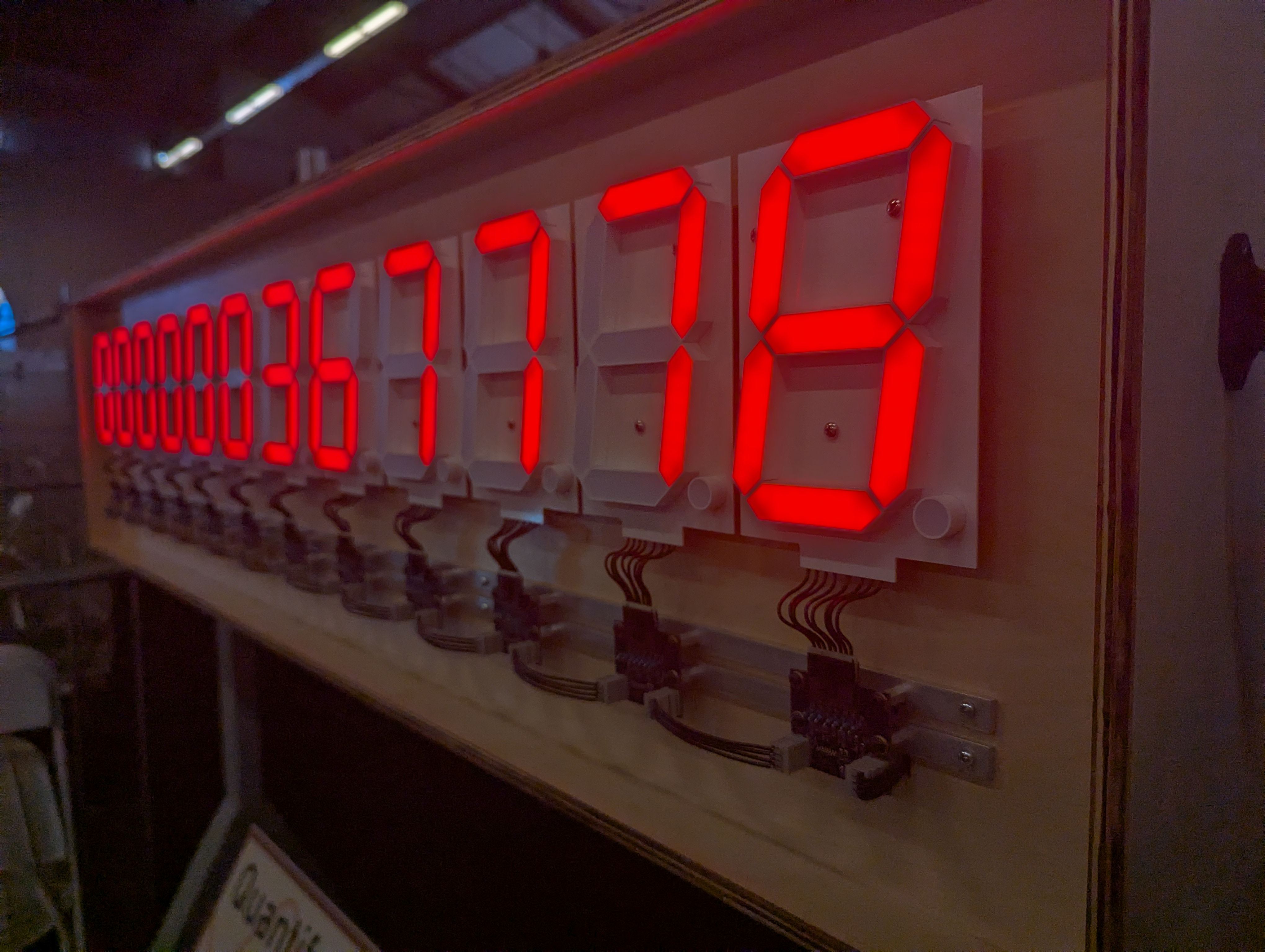
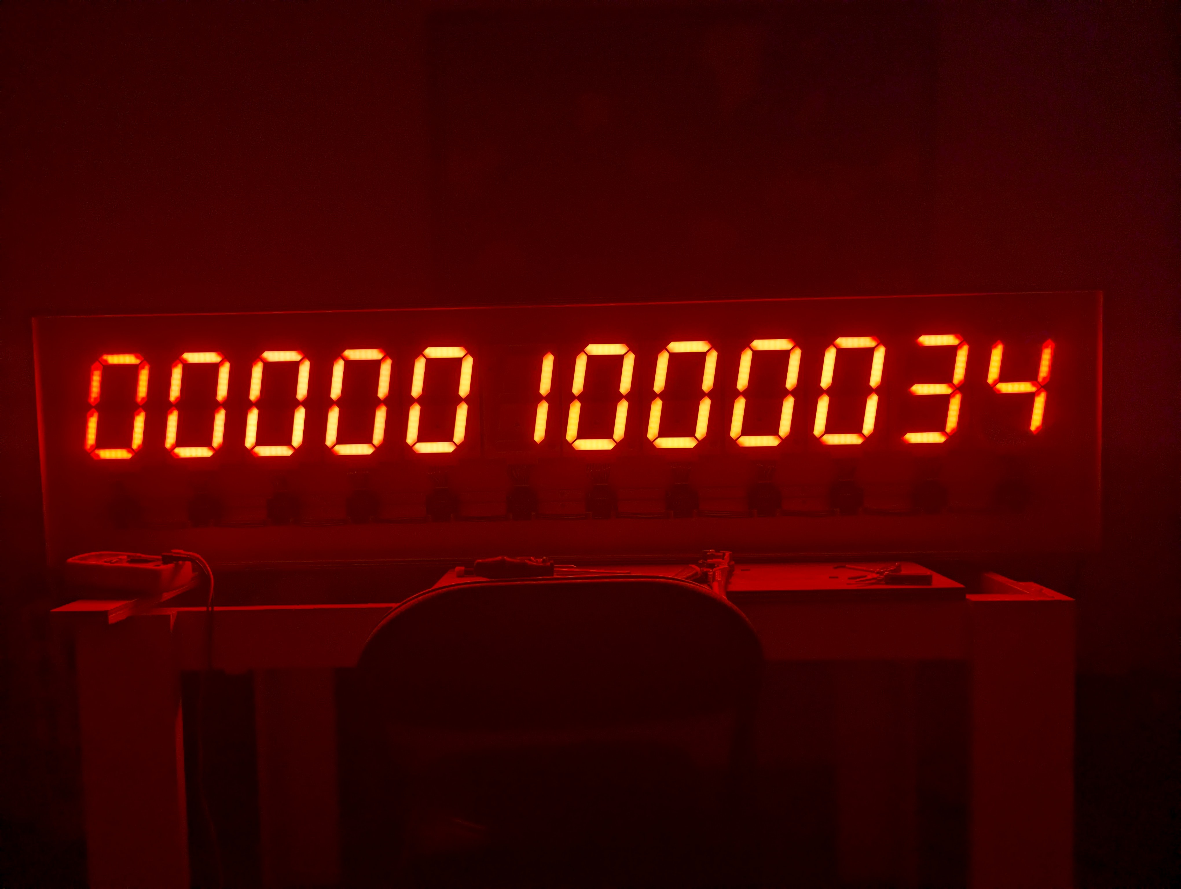
This art piece makes visual the living and breathing nature of the national power grid in real time. Once powered on, it monitors the grid's pulse by counting the beats, acting as a guage of the grid's current performance. If the art piece loses power, the displayed progress is lost. Counting restarts after power is restored, and the cycle resets from zero.
All of circuitry that makes up the art piece (with the exception of power supplies) is analog. Every digit is controlled by a sequential logic decade counter IC. Each digit's IC recives a clock signal from the prior digit and provides a clock signal to the subsequent digit's IC. The digit in the 1's place receives a rectified and attenuated clock signal originating from the AC waveform of the power grid. This means that the grid itself provides the primary clock of the piece.
Given that the United States power grid oscillates at 60Hz, this means that each digit increments at the following rate:
| Digit | Increment Time |
|---|---|
| 0 | 1/60th second |
| 1 | 1/6th second |
| 2 | 1.66 seconds |
| 3 | 17 seconds |
| 4 | 2.8 minutes |
| 5 | 28 minutes |
| 6 | 4.6 hours |
| 7 | 46 hours |
| 8 | 19.3 days |
| 9 | 193 days |
| 10 | 5.3 years |
| 11 | 53 years |
These values are calculated using the following equation:
$\frac{10^{d}}{60^{x} 24^{y} 365^{z}}$
d: zero indexed, the digit to inquire about
x: set to 1 for seconds, 2 for minutes, and 3 for hours.
y: provided that x is 3, set to 1 for time in days. Otherwise set to 0.
z: provided that x is 3 and y is 1, set to 1 for time in years. Otherwise set to 0.
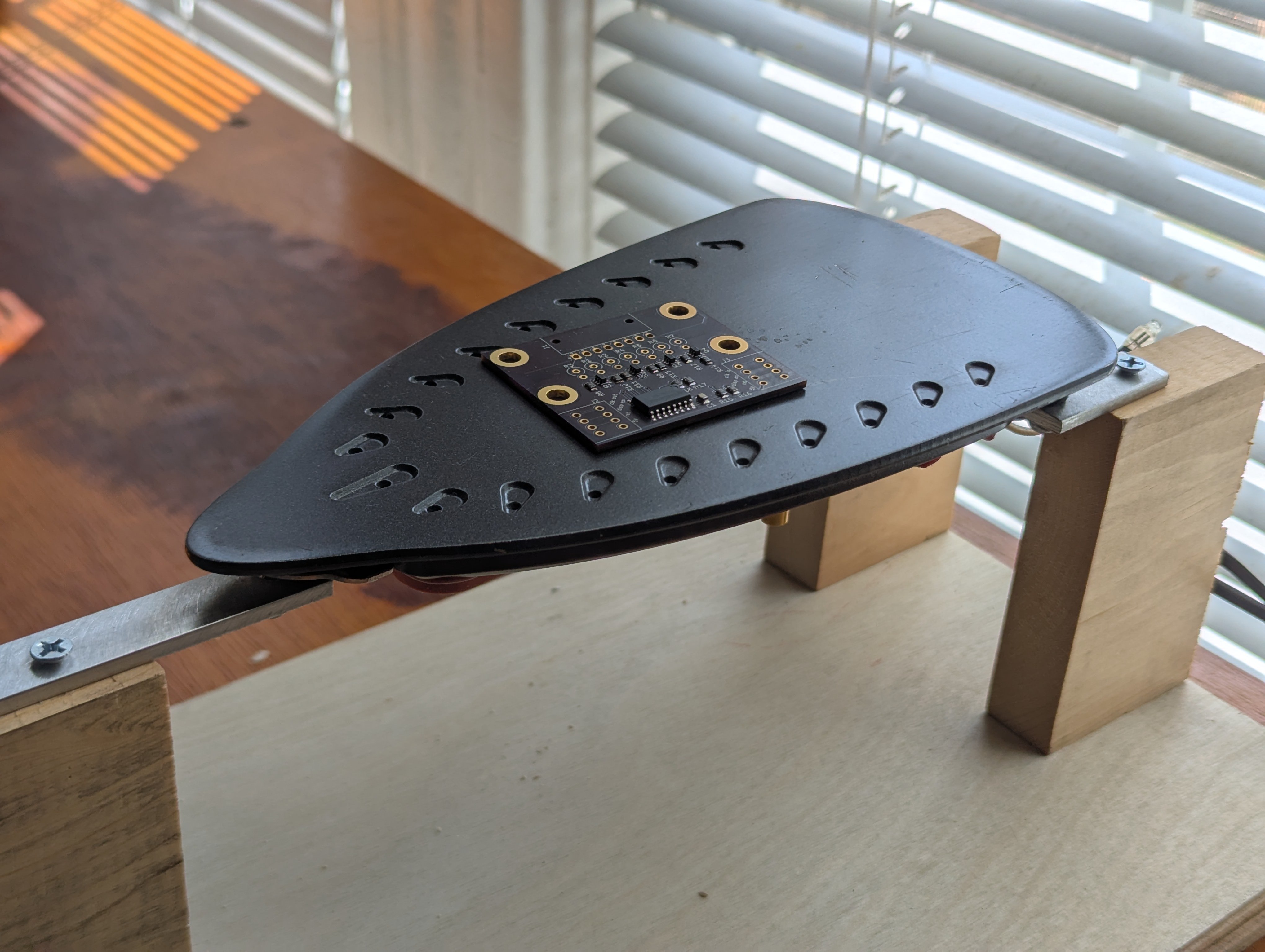
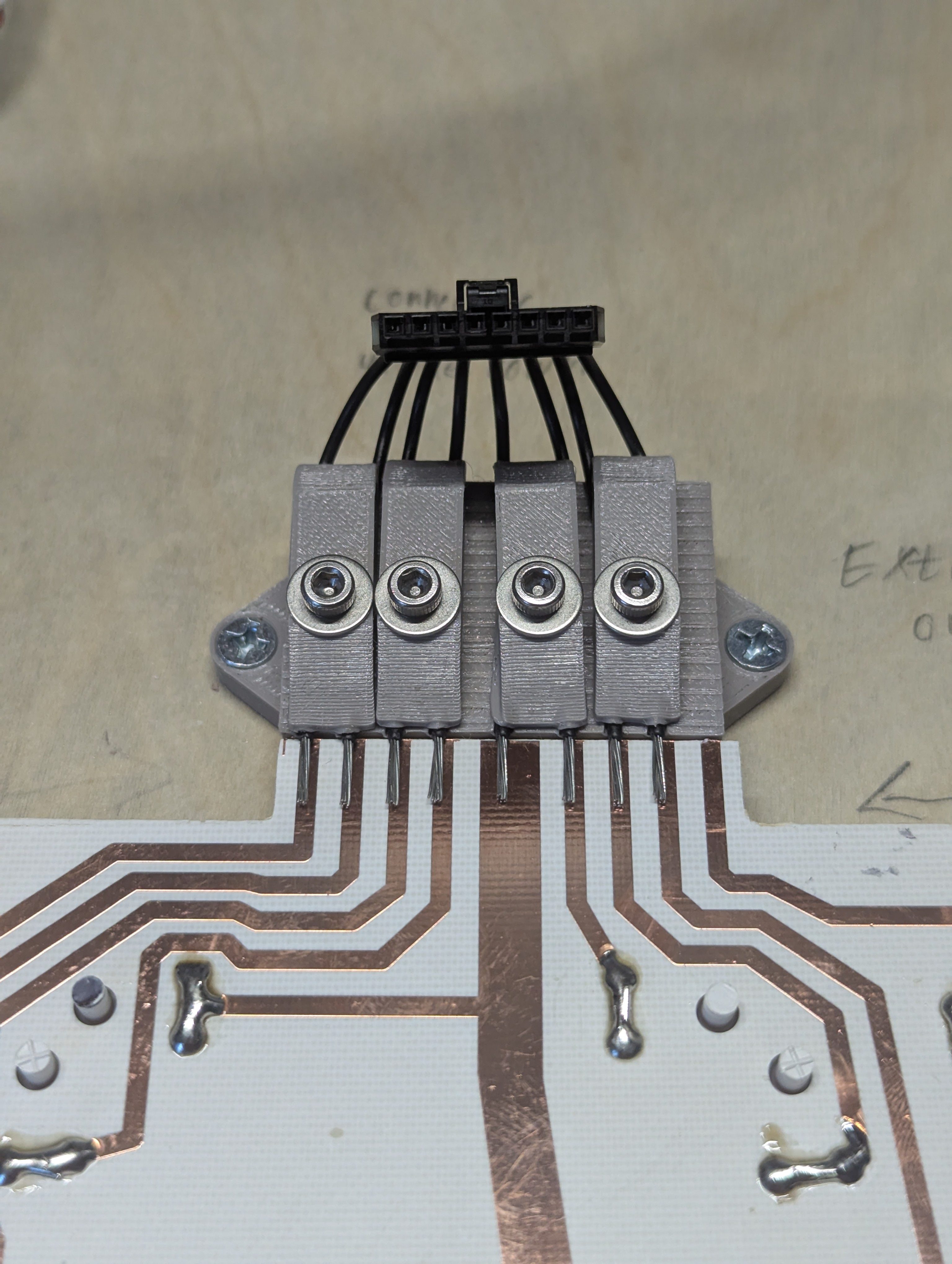
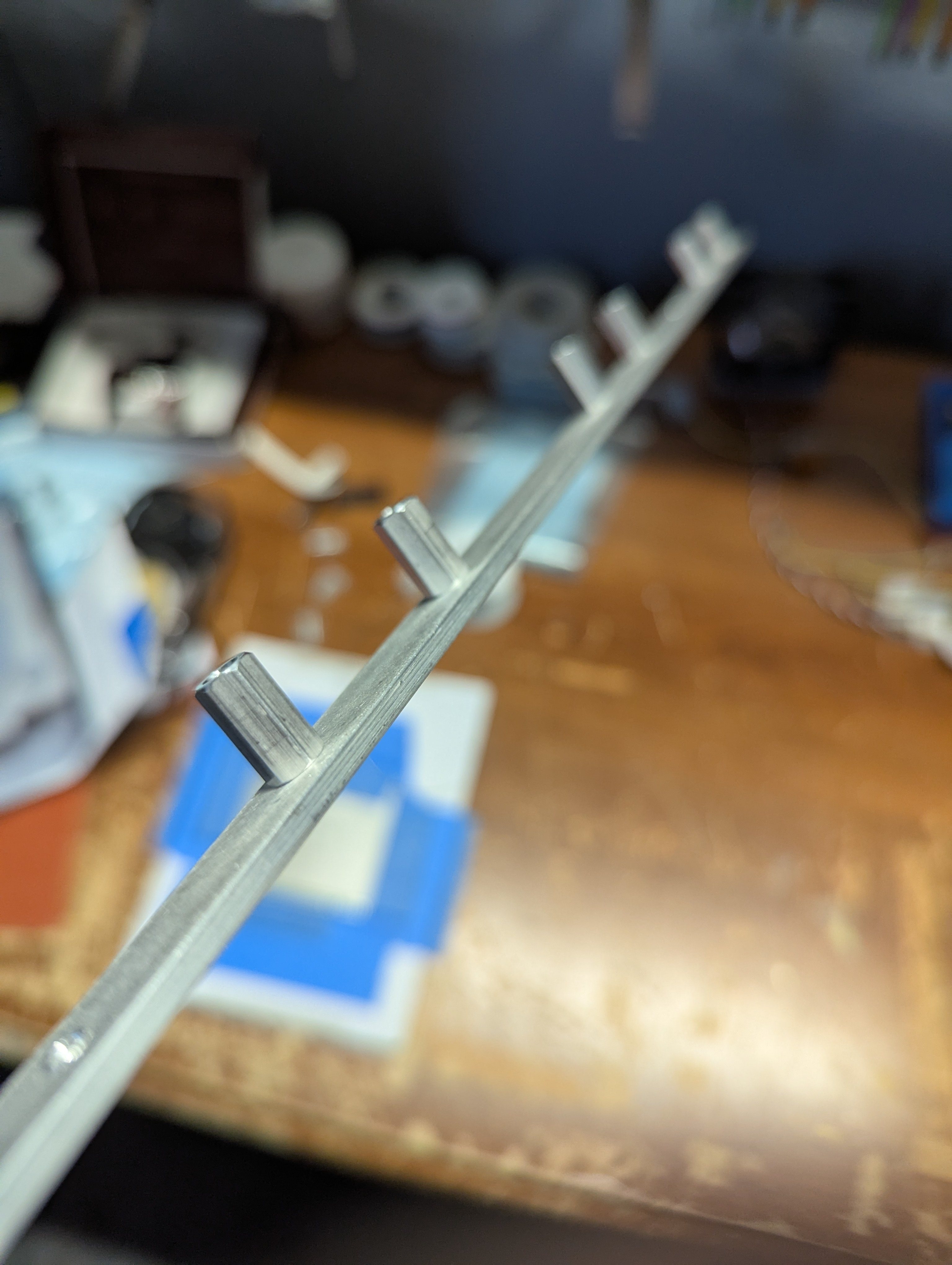
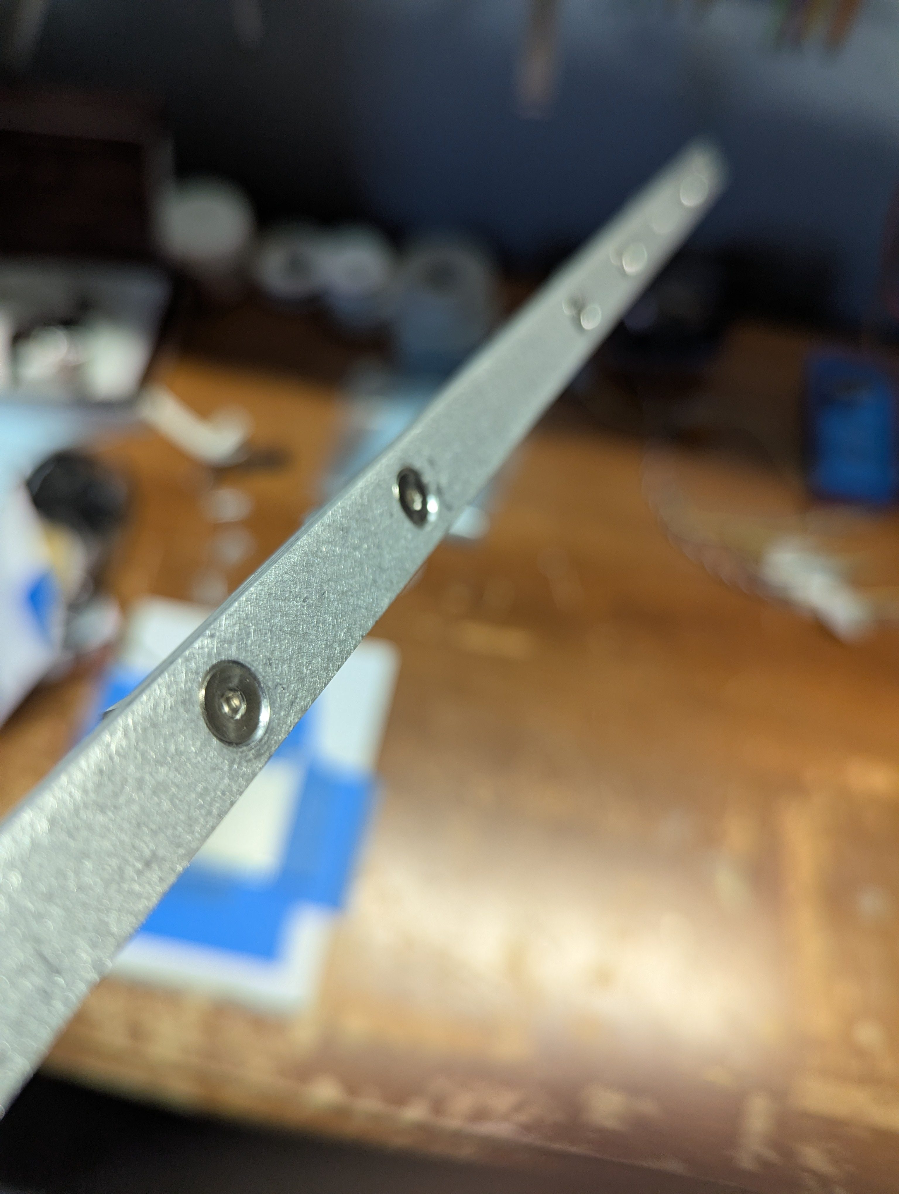
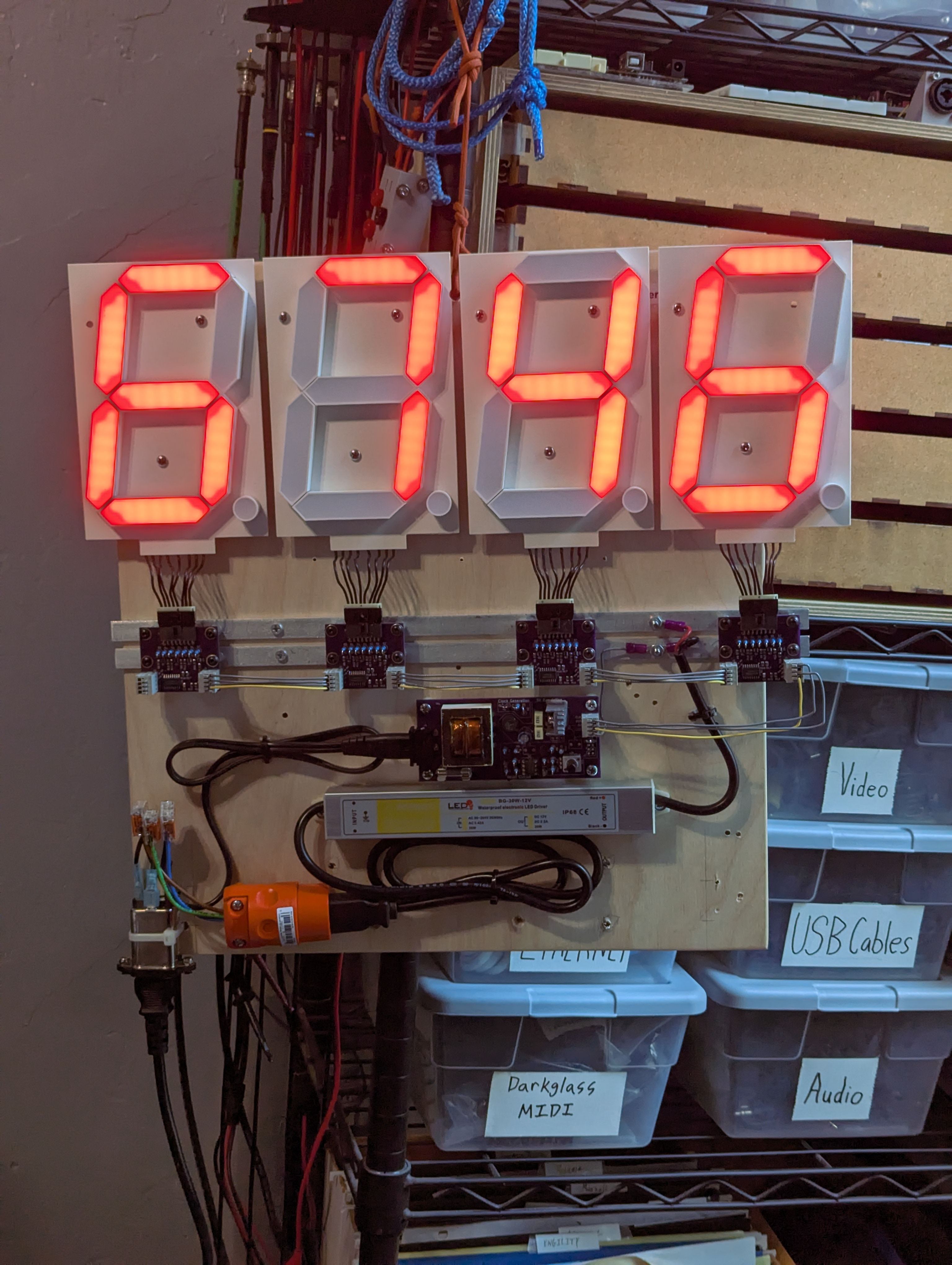
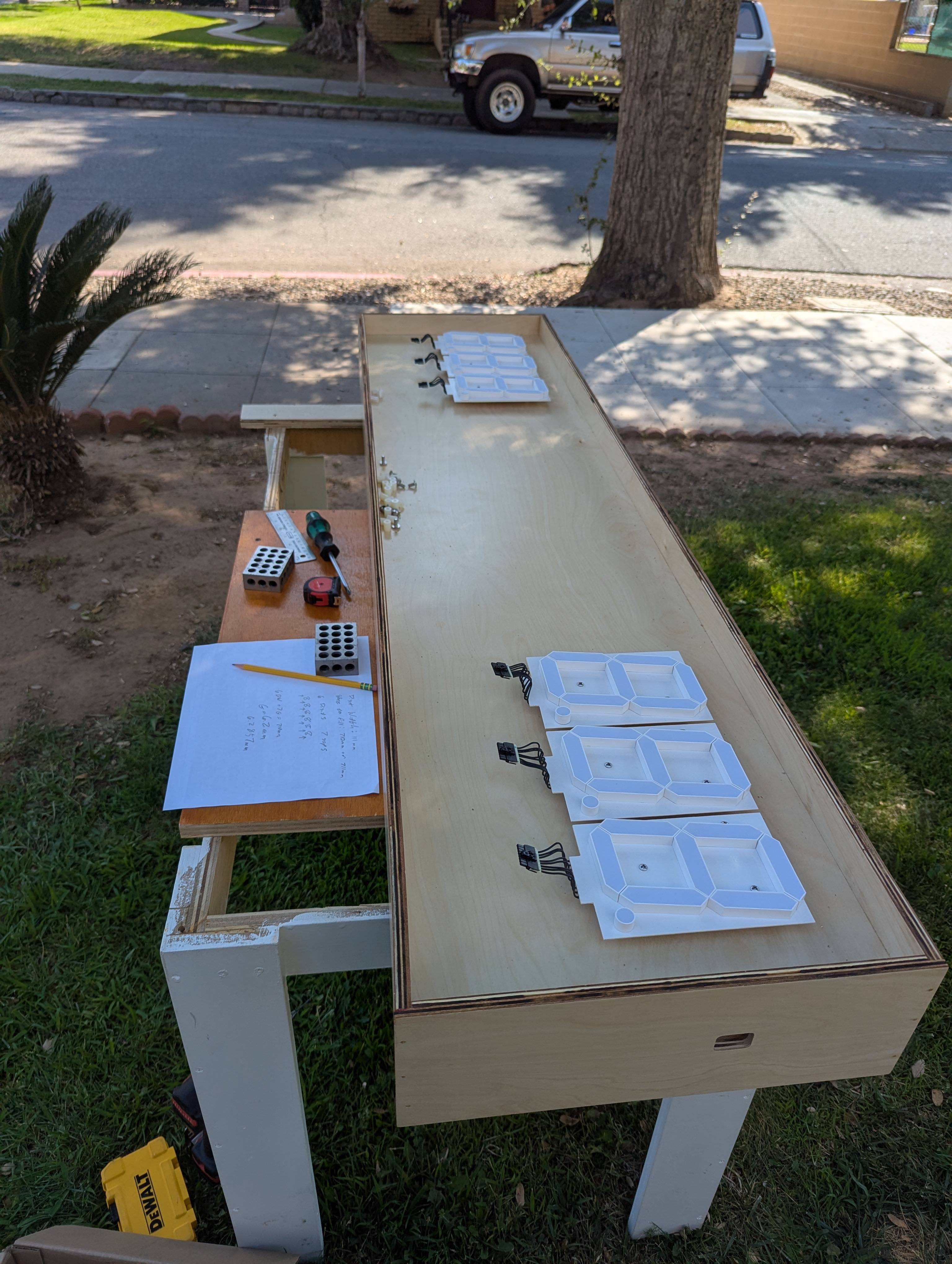
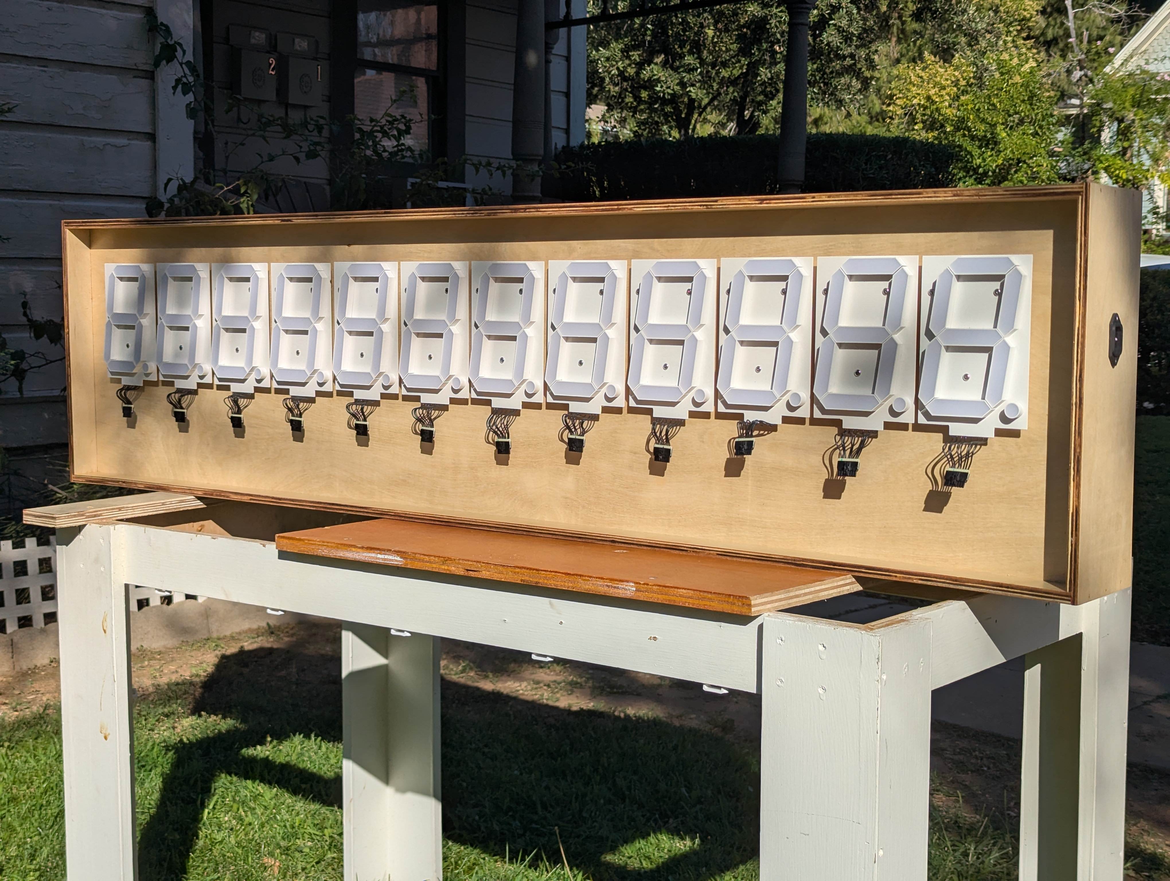
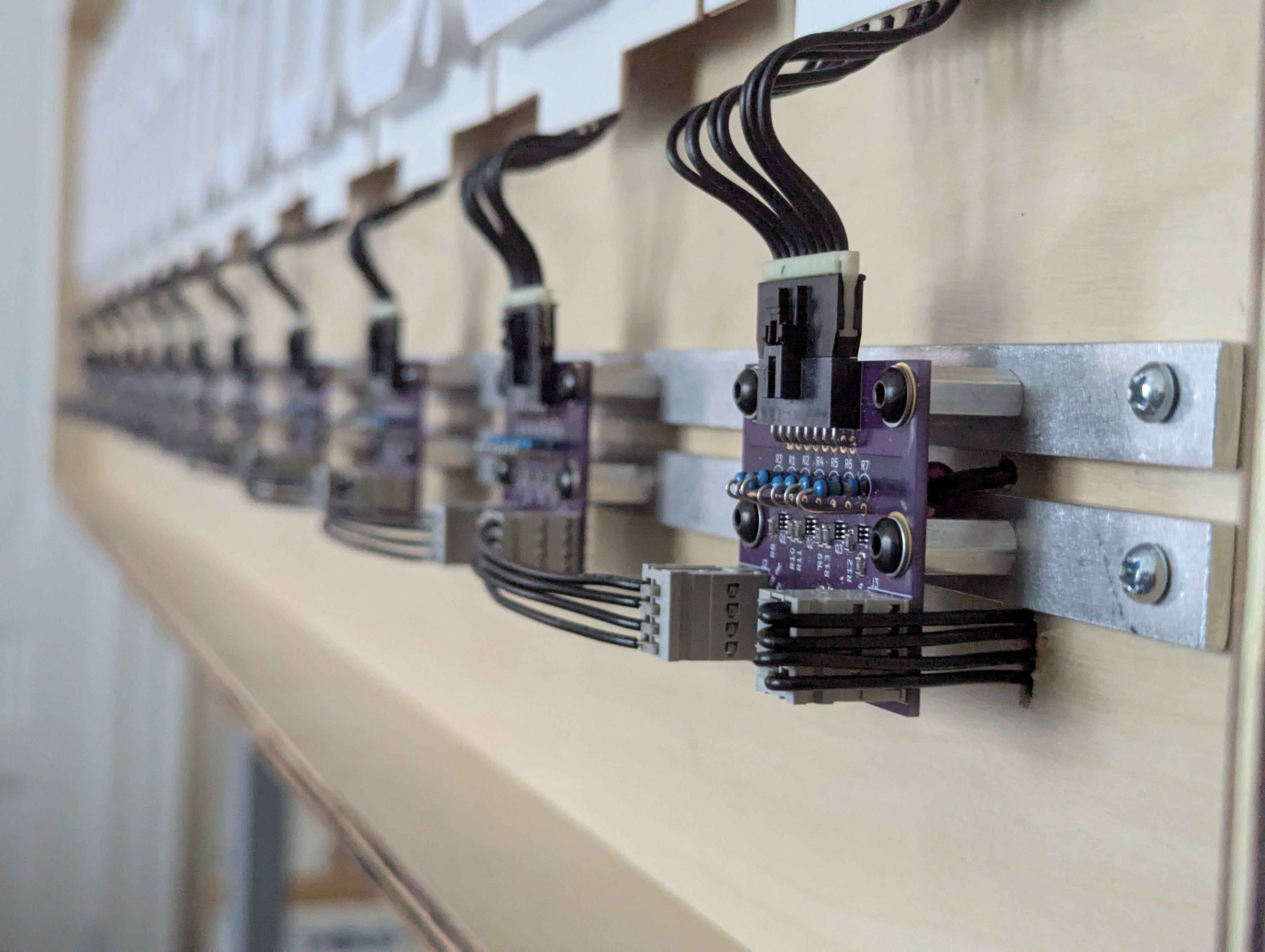
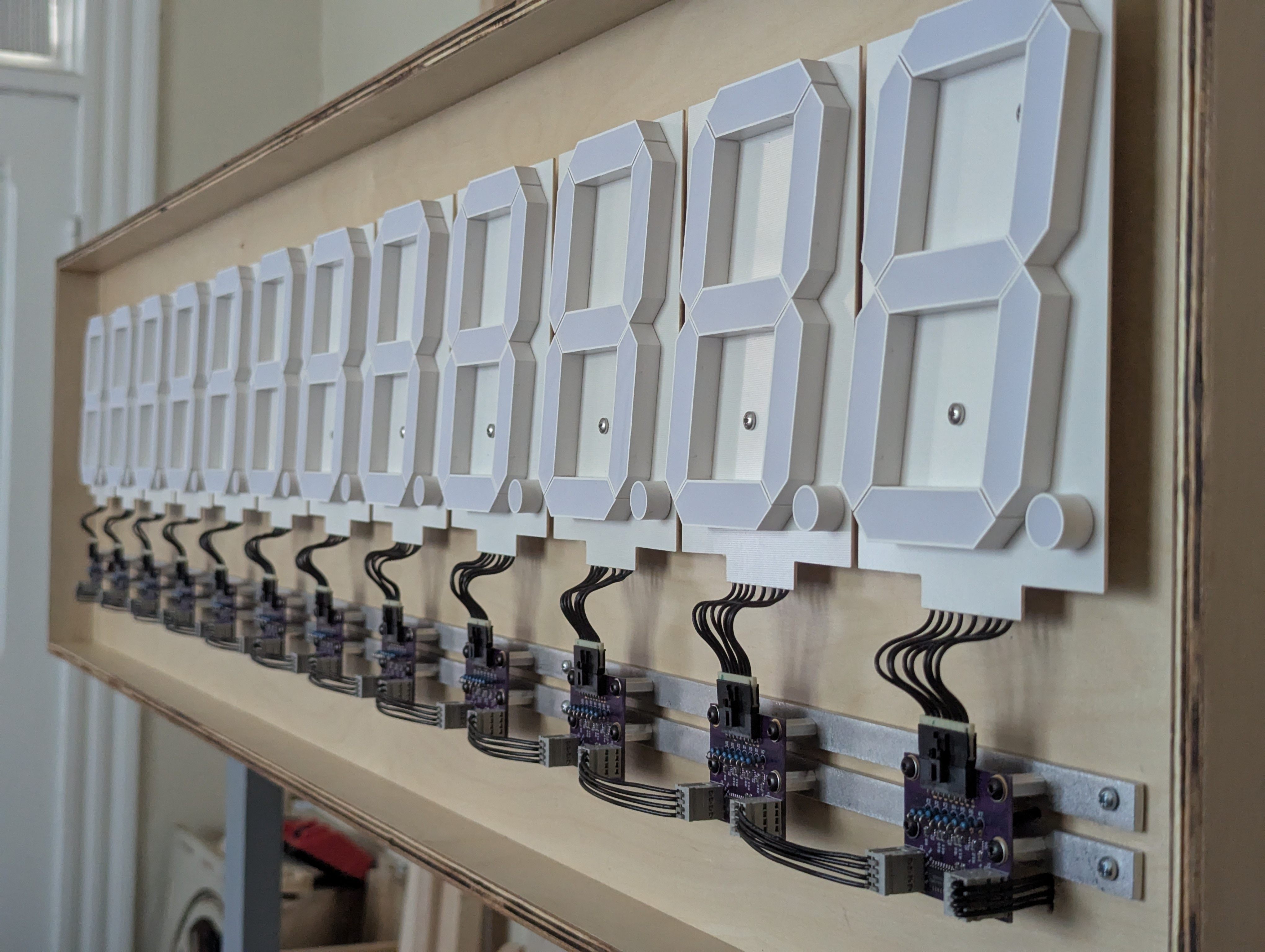
Below are some additional photos of the prototyping and building process
| Qty | Value | Footprint | References |
|---|---|---|---|
| 4 | 1k | Resistor_THT:R_Axial_DIN0207_L6.3mm_D2.5mm_P2.54mm_Vertical | R1, R5, R9, R10 |
| 4 | 1u | Capacitor_THT:C_Disc_D7.5mm_W5.0mm_P5.00mm | C1, C2, C5, C7 |
| 4 | MountingHole | MountingHole:MountingHole_4.3mm_M4 | H1, H2, H3, H4 |
| 2 | 10u | Capacitor_THT:CP_Radial_D4.0mm_P1.50mm | C4, C6 |
| 2 | PMOS | Package_TO_SOT_THT:TO-92_Inline | Q1, Q2 |
| 1 | 100k | Resistor_THT:R_Axial_DIN0207_L6.3mm_D2.5mm_P2.54mm_Vertical | R11 |
| 1 | 100k | customParts:Potentiometer_Bourns_PTV09 | RV1 |
| 1 | 100u | Capacitor_THT:CP_Radial_D8.0mm_P3.50mm | C3 |
| 1 | 10k | Resistor_THT:R_Axial_DIN0207_L6.3mm_D2.5mm_P2.54mm_Vertical | R12 |
| 1 | 125mA | Fuse:Fuseholder_Clip-5x20mm_Schurter_OG_Lateral_P15.00x5.00mm_D1.3mm_Horizontal | F1 |
| 1 | 1N4148 | Diode_THT:D_A-405_P5.08mm_Vertical_AnodeUp | D1 |
| 1 | 1N5230B | Diode_THT:D_A-405_P5.08mm_Vertical_KathodeUp | D2 |
| 1 | 2W06G | Diode_THT:Diode_Bridge_Round_D9.8mm | D3 |
| 1 | 33k | Resistor_THT:R_Axial_DIN0207_L6.3mm_D2.5mm_P2.54mm_Vertical | R8 |
| 1 | 360k | Resistor_THT:R_Axial_DIN0207_L6.3mm_D2.5mm_P2.54mm_Vertical | R4 |
| 1 | 5v_in | Connector_PinHeader_2.54mm:PinHeader_2x02_P2.54mm_Vertical | J3 |
| 1 | 6.8k | Resistor_THT:R_Axial_DIN0207_L6.3mm_D2.5mm_P2.54mm_Vertical | R3 |
| 1 | 620k | Resistor_THT:R_Axial_DIN0207_L6.3mm_D2.5mm_P2.54mm_Vertical | R7 |
| 1 | 68k | Resistor_THT:R_Axial_DIN0207_L6.3mm_D2.5mm_P2.54mm_Vertical | R6 |
| 1 | Conn_01x04_Socket | customParts:TBL009V-254-04 | J4 |
| 1 | IEC C8 | customParts:770W-X2_10 | J1 |
| 1 | L7805CV | Package_TO_SOT_THT:TO-220-3_Vertical | U1 |
| 1 | RST | Connector_PinHeader_2.54mm:PinHeader_2x02_P2.54mm_Vertical | J2 |
| 1 | TLC3702 | Package_DIP:DIP-8_W7.62mm_Socket | U2 |
| 1 | rstJump | Jumper:SolderJumper-3_P2.0mm_Open_TrianglePad1.0x1.5mm_NumberLabels | JP2 |
| 1 | vccJump | Jumper:SolderJumper-3_P2.0mm_Open_TrianglePad1.0x1.5mm_NumberLabels | JP1 |
| 1 | ~ | customParts:F28-085-C2 | TR1 |
It measures 111.8 × 50.8 mm and has 2 copper layers, 1.6 mm thick.
38 parts, built around the L7805CV, TLC3702CP, MBB02070C1001FCT00 and R82DC4100AA60K. The full list of its parts is on this page, with links to each part's symbol and footprint where PCBKit's library has them.
From the martinbros/Quantifying-the-Current repository on GitHub, at the commit this page was made from: the board is wallClockGen/wallClockGen.kicad_pcb and its schematic segmentCounter/segmentCounter.kicad_sch. PCBKit opens the board in the browser, with nothing to install.
Its repository publishes it under the GPL-3.0 licence: you may reuse it on that licence's terms (keep the author's notice, and for a copyleft licence share your changes alike).
martinbros/Quantifying-the-Current
Art piece demonstrating the power grid


markrvmurray/pico-thing
An 8-bit MC6809E / HD6309E single-board computer with a pair of Raspberry Pi Pico 2 (RP2350 / Pimoroni PGA2350) modules acting as intelligent bus peripherals, a 1–2 MB banked-RAM DAT/MMU, a 40-pin PATA hard-disk…


jackw01/scanlight
A better light source for scanning color negative film


Phil-dav/mailbox-lora-tracker
Weight-sensing mailbox notifier: Heltec ESP32 + LoRa + HX711 load cells