2 layers194.3 × 174 mm

 martinber/z80mgc
z80 game console
Z80mgc is an open-source printed circuit board by martinber, from the martinber/z80mgc repository on GitHub, published under the GPL-3.0 licence. It is a 4-layer board of 190 × 120 mm with 91 parts on 126 nets, routed with 1,146 tracks and 63 vias.
It is built around the 74HC245D, 74HC00D and 74HC02, with the 74HC04D, 74HC138 and 74HC86D among its other parts. Its parts include 20 connectors, 17 diodes, 14 resistors, 11 ICs and 4 capacitors. It belongs with the retro computing and games boards of this library.


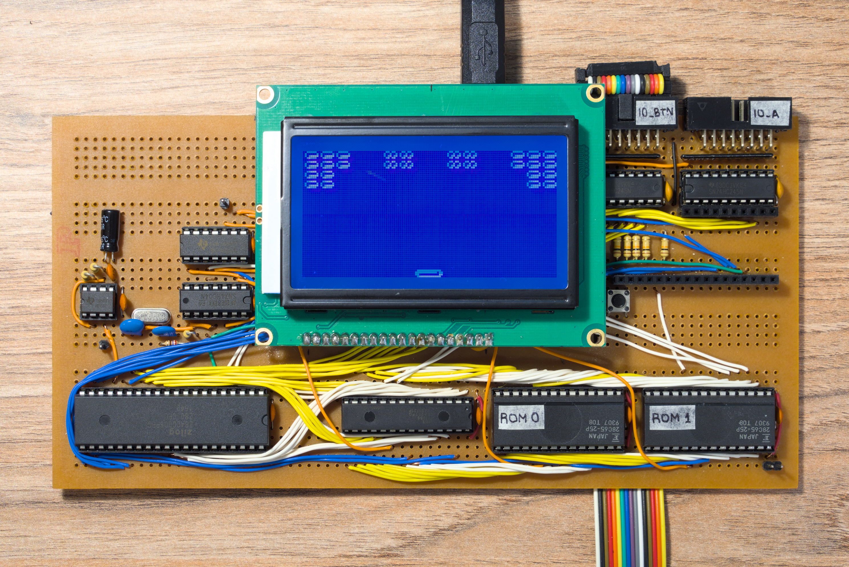
A minimal game console based on the z80 CPU. Something like a console from the 70s/80s such as the original PAC-MAN arcade, but without video/sound chips which are hard to find.
This repo contains:
Board:
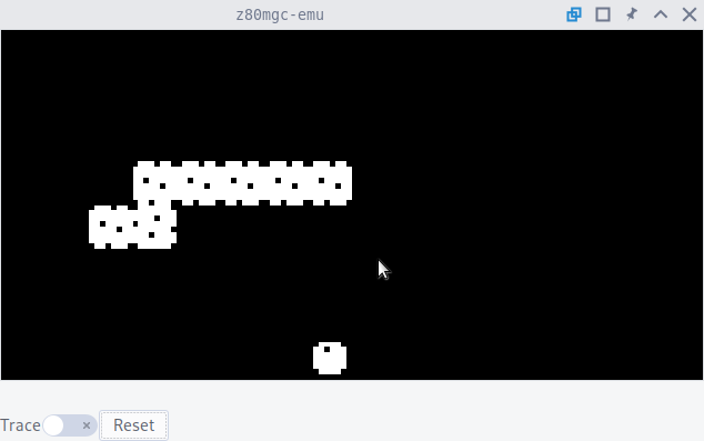
Emulator:
Specs:
Working games:
Possible future games:
I can use RAM/ROM at full speed without caring about read times:
I can read the LCD without caring about read times. But LCD instructions are slow, I always have to poll if it is ready before using it:
LCD speed:
I don't have a timer chip like the z80 CTC. So I can count in software the amount of NMI, comes from a 555 timer. The interrupt happens at falling edge so there is no problem on leaving the NMI pin low for a long time.
The counter will be 8 bit. The value 255 could be equivalent to approx 2s so in that case I should call NMI at approx 128Hz. I do this with a 555 which apparently can reach until 100kHz.
Game start:
Game loop, in order:
Ball: Clear old position of ball and move ball coordinate
Bricks: If collision with ball, redraw if modified or draw zeros to clean area.
Powerups: If collision with pad, draw zeros to clean area and give powerup.
Powerups: Draw the 8x3 graphic with OR. Should draw even if not descending because if the ball comes and it is stationary then there will be conflicts, but very unlikely and avoidable if both ball and powerup move together
Pad: Draw with OR with shifting/rotation.
Ball: Draw with OR with shifting/rotation.
Powerups:
Bigger pad
Smaller pad
Faster ball
Slower ball
Extra ball
Move all bricks downwards
Extra life
Will have a DUL (Drawing Update List) containing coordinates and the byte of graphics that will be drawn. Some kind of compressed framebuffer. This is used so I can overlap graphics with AND operations in RAM before writing to the LCD.
Game start:
Drawing/updating, in order:
Bricks: If collision with ball, redraw if modified or draw zeros to clean area.
Powerups: If collision with pad, draw zeros to clean area and give powerup.
Powerups: Draw in the DUL the 8x4 graphic. The graphic is actually 8x3 but the top line is empty so it will erase the old frame. Draw even if not descending because if the ball comes and it is stationary then there will be conflicts
Pad: Draw in the DUL using shifting/rotation.
Ball: Draw in the DUL using shifting/rotation.
Old ideas:
Powerups: Collision detection with ball and pad, redraw to clean area in that case. If moving downward in this frame, draw full 8x4 object. The graphic is actually 8x3 but the top line is empty so it will erase the previous. Will be destroyed as soon as it touches the ball or the pad, so no problems in drawing order.
Pad: Draw using shifting/rotation. Draw each time it moves. Draw it in a framebuffer that only covers the last
Ball: Draw using shifting/rotation. Draw each time it moves, do it last
Ground plane in the back layer?
Check datasheet for recommendations of decoupling capacitors
Check "return paths" for high speed signals
Route more important signals first so I minimize the length, vias, etc.
Add test points, with ground clips
Add mounting holes in corners first
I can add jumper resistors
I can make the SRAM with wide holes too
Vertial traces in one side and horizontal traces on the other, that way the ground plane is mostly intact
No 90deg angles, https://www.alternatezone.com/electronics/files/PCBDesignTutorialRevA.pdf
"I rarely go smaller than 10 mil for any trace unless I have to, and for power I try to use at least 30 mil" As a start, you may like to use say 25 thou for signal tracks, 50 thou for power and ground tracks, and 10-15 thou for going between IC and component pads
Pads 2x the diameter og the hole. There are some common practices used when it comes to generic component pads. Pads for leaded components like resistors, capacitors and diodes should be round, with around 70 thou diameter being common. Dual In Line (DIL) components like IC’s are better suited with oval shaped pads (60 thou high by 90-100 thou wide is common). Pin 1 of the chip sould always be a different pad shape, usually rectangular, and with the same dimensions as the other pins.p
At least 15 thou is a good clearance limit for basic through hole designs
Ensure that no part of the silkscreen overlaps a bare pad.
As a general rule, you should use at least one bypass capacitor per IC or other switching component if possible. Common values of bypass capacitors are 100nF for general purpose use, 10nF or 1nF for higher frequencies, and 1uF or 10uF for low frequencies.
Put name and description in silkscreen
Check that solder points have thermal relief pads
| Qty | Value | Footprint | References |
|---|---|---|---|
| 14 | LED | LED_THT:LED_D3.0mm | D0, D1, D2, D3, D4, D5, D6, D7, D9, D13, D14, D15, D16, D17 |
| 11 | 0.1uF | Capacitor_THT:C_Disc_D3.0mm_W1.6mm_P2.50mm | CD1, CD2, CD3, CD5, CD6, CD7, CD9, CD10, CD11, CD12, CD13 |
| 8 | 1k | Resistor_THT:R_Axial_DIN0207_L6.3mm_D2.5mm_P10.16mm_Horizontal | R1, R2, R3, R4, R5, R18, R22, R23 |
| 4 | 10k | Resistor_THT:R_Axial_DIN0207_L6.3mm_D2.5mm_P10.16mm_Horizontal | R2, R3, R4, R21 |
| 3 | , , | ||
| 2 | 10k | Resistor_THT:R_Array_SIP9 | RN1, RN2 |
| 2 | 1k | Resistor_THT:R_Array_SIP9 | RN3, RN4 |
| 2 | 1k | Resistor_THT:R_Array_SIP7 | RN5, RN6 |
| 2 | 28C256 | Package_DIP:DIP-28_W15.24mm_LongPads | U5, U6 |
| 2 | 33pF | Capacitor_THT:C_Disc_D4.3mm_W1.9mm_P5.00mm | C3, C5 |
| 2 | 74HC245 | Package_DIP:DIP-20_W7.62mm_Socket_LongPads | U9, U10 |
| 1 | clipboard:a9ab44e1-df2f-4d8c-8125-f91eaead8355 | ||
| 1 | 0.1uf | Capacitor_THT:C_Disc_D3.0mm_W1.6mm_P2.50mm | C4 |
| 1 | 100k | Resistor_THT:R_Axial_DIN0207_L6.3mm_D2.5mm_P10.16mm_Horizontal | R19 |
| 1 | 1uF | Capacitor_THT:CP_Radial_D5.0mm_P2.50mm | C2 |
| 1 | 260 | Resistor_THT:R_Axial_DIN0204_L3.6mm_D1.6mm_P5.08mm_Horizontal | R20 |
| 1 | 6MHz | Crystal:Crystal_HC49-4H_Vertical | Y1 |
| 1 | 71256 | Package_DIP:DIP-28_W7.62mm_Socket_LongPads | U1 |
| 1 | 74HC00 | Package_DIP:DIP-14_W7.62mm_Socket_LongPads | U2 |
| 1 | 74HC02 | Package_DIP:DIP-14_W7.62mm_Socket_LongPads | U4 |
| 1 | 74HC04 | Package_DIP:DIP-14_W7.62mm_Socket_LongPads | U3 |
| 1 | 74HC138 | Package_DIP:DIP-16_W7.62mm_Socket_LongPads | U7 |
| 1 | 74HC86 | Package_DIP:DIP-14_W7.62mm_Socket_LongPads | U8 |
| 1 | F | Capacitor_THT:C_Disc_D3.0mm_W1.6mm_P2.50mm | CD4 |
| 1 | IO_A | z80mgc:PinHeader_2x08_P2.54mm_Vertical | J1 |
| 1 | IO_BTN | z80mgc:PinHeader_2x08_P2.54mm_Vertical | J3 |
| 1 | IO_EXP | z80mgc:PinHeader_2x08_P2.54mm_Vertical | J6 |
| 1 | NE555P | Package_DIP:DIP-8_W7.62mm | U12 |
| 1 | POWER | Connector_PinHeader_2.54mm:PinHeader_1x02_P2.54mm_Vertical | J4 |
| 1 | QC12864B | z80mgc:QC12864B_Header | DS1 |
| 1 | RESET | Connector_PinSocket_2.54mm:PinSocket_1x02_P2.54mm_Vertical | J5 |
| 1 | USB_B | Connector_USB:USB_B_OST_USB-B1HSxx_Horizontal | J2 |
| 1 | Z80CPU | Package_DIP:DIP-40_W15.24mm_Socket_LongPads | CPU1 |
| 1 | ~{BUSACK} | Connector_PinHeader_1.27mm:PinHeader_1x01_P1.27mm_Vertical | J20 |
| 1 | ~{BUSRQ} | Connector_PinHeader_1.27mm:PinHeader_1x01_P1.27mm_Vertical | J14 |
| 1 | ~{CLK} | Connector_PinHeader_1.27mm:PinHeader_1x01_P1.27mm_Vertical | J11 |
| 1 | ~{HALT} | TestPoint:TestPoint_THTPad_D2.0mm_Drill1.0mm | J9 |
| 1 | ~{IORQ} | Connector_PinHeader_1.27mm:PinHeader_1x01_P1.27mm_Vertical | J19 |
| 1 | ~{M1} | Connector_PinHeader_1.27mm:PinHeader_1x01_P1.27mm_Vertical | J7 |
| 1 | ~{MREQ} | Connector_PinHeader_1.27mm:PinHeader_1x01_P1.27mm_Vertical | J18 |
| 1 | ~{MREQ} | LED_THT:LED_D3.0mm | D12 |
| 1 | ~{NMI} | Connector_PinHeader_1.27mm:PinHeader_1x01_P1.27mm_Vertical | J8 |
| 1 | ~{RD} | LED_THT:LED_D3.0mm | D10 |
| 1 | ~{RD} | Connector_PinHeader_1.27mm:PinHeader_1x01_P1.27mm_Vertical | J16 |
| 1 | ~{RESET} | Connector_PinHeader_1.27mm:PinHeader_1x01_P1.27mm_Vertical | J15 |
| 1 | ~{RFSH} | TestPoint:TestPoint_THTPad_D2.0mm_Drill1.0mm | J12 |
| 1 | ~{RFSH} | Connector_PinHeader_1.27mm:PinHeader_1x01_P1.27mm_Vertical | J13 |
| 1 | ~{WAIT} | Connector_PinHeader_1.27mm:PinHeader_1x01_P1.27mm_Vertical | J10 |
| 1 | ~{WR} | Connector_PinHeader_1.27mm:PinHeader_1x01_P1.27mm_Vertical | J17 |
| 1 | ~{WR} | LED_THT:LED_D3.0mm | D11 |


nailed-barnacle/Cisc-8-ttl-processor
A cut-down version of the 8080 processor using HCTTL and including a discrete ALU and instruction decoder

slu4coder/Minimal-UART-Computer-1-2
Legacy: Version 1 and 2 of my TTL-only CPU featuring UART I/O, an expansion port, 512KB SSD at up to 10MHz clock speed

Trilobyte-CPU/8-bit-computer
A DIY 8-bit computer built mostly with discrete logic chips


It measures 190 × 120 mm and has 4 copper layers, 1.6 mm thick.
91 parts, built around the 74HC245D, 74HC00D, 74HC02 and 74HC04D. The full list of its parts is on this page, with links to each part's symbol and footprint where PCBKit's library has them.
From the martinber/z80mgc repository on GitHub, at the commit this page was made from: the board is hw/z80mgc.kicad_pcb and its schematic hw/io.kicad_sch. PCBKit opens the board in the browser, with nothing to install.
Its repository publishes it under the GPL-3.0 licence: you may reuse it on that licence's terms (keep the author's notice, and for a copyleft licence share your changes alike).