

2 layers245.1 × 160 mm
8-Bit CPU 32k
slu4coder/Minimal-64x4-Home-Computer
My DIY TTL home computer with VGA and PS/2 and 4x the processing power of a Commodore C64 or Apple II.
139 parts326
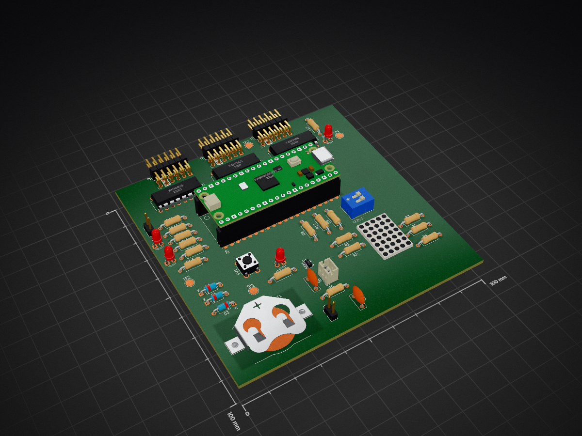
 marnovandermaas/LED_matrix_PCB
This PCB is meant to write and read from PMOD pins and drive an LED matrix based on these pins. There will be a microcontroller that drives the LED matrix so it can also have an independent program to display arbitrary…
Hackday13 is an open-source printed circuit board by marnovandermaas, from the marnovandermaas/LED_matrix_PCB repository on GitHub. It is a 4-layer board of 100 × 100 mm with 48 parts on 81 nets.
It is built around the 74HC165D and 74HC595. Its parts include 19 resistors, 7 diodes, 7 connectors, 5 ICs and 2 capacitors. It belongs with the lEDs and displays boards and the RP2040 boards of this library.
This PCB is meant to write and read from PMOD pins and drive an LED matrix based on these pins. There will be a microcontroller that drives the LED matrix so it can also have an independent program to display arbitrary things on the matrix.
The PCB should be able to be powered externally as well as through a battery. The reason to want to use a battery is that it can then be used as a conference badge to display a name on.
The PCB should connect to the Tiny Tapeout demo board, and specifically with this factorizer design that uses the bidirectional pins solely for output.

Components should be through hole to ease soldering.
Row-wise (one row at a time):
Column-wise (one column at a time):
Try using PIO to do the high-frequency stuff? PIO emulator.
12 GPIO for the LEDs.
7 GPIO for PMOD output to Tiny Tapeout.
5 GPIO pins for PMOD input from Tiny Tapeout. Connect some to UART pins.
2 GPIO (or 1 ADC pin) for DIP switches.
Connect RUN pin to a normally-open momentary switch to GND to get a Reset button.
We'll probably use a cheap PCB manufacturer like: JLC. Previously I had also considerd PCB way.
To make sure we can drive all the PMOD input and output, we were thinking it's a good idea to use a shift register to save GPIO pins on the Pico. One thing Elliot mentioned was it would be good to have one full PMOD directly connected to the GPIO so that UART still works.
8-bit parallel input to serial output: TI SN74HC165N, 8 inputs with 1 ouput and 2 control signals.
Serial input to 8-bit parallel output: TI SN74HC595N, 8 outputs with 1 input and 2 control signals.
Harry's tip: use 74-series logic to get good datasheets.
| Qty | Value | Footprint | References |
|---|---|---|---|
| 8 | 200 Ohm | Resistor_THT:R_Axial_DIN0207_L6.3mm_D2.5mm_P10.16mm_Horizontal | R1, R2, R3, R4, R5, R13, R18, R19 |
| 6 | 0 | Resistor_THT:R_Axial_DIN0207_L6.3mm_D2.5mm_P10.16mm_Horizontal | R11, R12, R14, R15, R16, R17 |
| 4 | LED | LED_THT:LED_D3.0mm | D2, D5, D6, D7 |
| 4 | TestPoint | TestPoint:TestPoint_Pad_D3.0mm | TP1, TP2, TP3, TP4 |
| 3 | 1k | Resistor_THT:R_Axial_DIN0207_L6.3mm_D2.5mm_P10.16mm_Horizontal | R8, R9, R10 |
| 3 | Conn_01x02_Pin | Connector_PinHeader_2.54mm:PinHeader_1x02_P2.54mm_Vertical | J4, J5, J7 |
| 3 | D_Schottky | Diode_THT:D_DO-35_SOD27_P7.62mm_Horizontal | D1, D3, D4 |
| 2 | 4.7u | Capacitor_THT:C_Disc_D7.0mm_W2.5mm_P5.00mm | C1, C2 |
| 2 | 74HC165 | Package_DIP:DIP-16_W7.62mm | U3, U4 |
| 1 | 1000 Ohm | Resistor_THT:R_Axial_DIN0207_L6.3mm_D2.5mm_P10.16mm_Horizontal | R7 |
| 1 | 2k | Resistor_THT:R_Axial_DIN0207_L6.3mm_D2.5mm_P10.16mm_Horizontal | R6 |
| 1 | 74HC595 | Package_DIP:DIP-16_W7.62mm | U5 |
| 1 | Battery_Cell | Battery:BatteryHolder_Keystone_3002_1x2032 | BT1 |
| 1 | Conn_01x02_Pin | Connector_JST:JST_PH_B2B-PH-K_1x02_P2.00mm_Vertical | J6 |
| 1 | LED dot matrix 12 pin | custom_components_led_pcb:LED_dot_matrix_TA07-11SEKWA | LEDs1 |
| 1 | MCP73831-4-OT | Package_TO_SOT_SMD:SOT-23-5 | U1 |
| 1 | RaspberryPi_Pico_W | Module_RaspberryPi_Pico:RaspberryPi_Pico_Common | U2 |
| 1 | Reset button | Button_Switch_THT:SW_PUSH_6mm | SW1 |
| 1 | SW_DIP_x02 | Button_Switch_THT:SW_DIP_SPSTx02_Slide_9.78x7.26mm_W7.62mm_P2.54mm | SW2 |
| 1 | TT-bidirectional | TinyTapeout:PinHeader_2x06_P2.54mm_PMODPeriph2B | J3 |
| 1 | TT-input | TinyTapeout:PinHeader_2x06_P2.54mm_PMODPeriph2B | J2 |
| 1 | TT-output | TinyTapeout:PinHeader_2x06_P2.54mm_PMODPeriph2B | J1 |
slu4coder/Minimal-64x4-Home-Computer
My DIY TTL home computer with VGA and PS/2 and 4x the processing power of a Commodore C64 or Apple II.

westlicht/performer-hardware
PER|FORMER Eurorack Sequencer - Hardware Design Files

slu4coder/Minimal-64-Home-Computer
Legacy: Full TTL-only home computer with VGA and PS/2 and twice the processing power of a Commodore 64

slu4coder/Minimal-UART-Computer-3
Version 3 of my educational DIY TTL computer built around a UART serial interface - now with blinkenlights!

robsonsmartins/usbflashprog
A memory device programmer (Flash/EPROM/E2PROM) board and software, connected to PC by USB port.


Windfisch/midikraken
A open source, open hardware up-to-16x USB-MIDI-interface for around 15 bucks in its smallest configuration.

It measures 100 × 100 mm and has 4 copper layers, 1.67 mm thick.
48 parts, built around the 74HC165D and 74HC595. The full list of its parts is on this page, with links to each part's symbol and footprint where PCBKit's library has them.
From the marnovandermaas/LED_matrix_PCB repository on GitHub, at the commit this page was made from: the board is hackday13.kicad_pcb and its schematic hackday13.kicad_sch. PCBKit opens the board in the browser, with nothing to install.
Its repository states no licence, so its author keeps all rights: ask marnovandermaas before reusing the design.