Skip to the content
PCBKitNew board
4 layers34 × 80 mmLAN Tester, the printed circuit board in 3D

Portable Raspberry Pi Pico LAN tester with W5500 Ethernet, OLED display and battery charging.

Size
34 × 80 mm
Copper layers
4
Thickness
1.6 mm
Parts
51
Nets
86
Pads
306
Tracks, vias
473, 158
Pours
5
Routed
Yes
KiCad
KiCad 9.0 (file 20241229)
Created
29 Apr 2026
Updated
29 Apr 2026

Overview

LAN Tester is an open-source printed circuit board by Markuselectronics, from the Markuselectronics/Raspberry-Pi-Pico-LAN-Tester repository on GitHub. It is a 4-layer board of 34 × 80 mm with 51 parts on 86 nets, routed with 473 tracks and 158 vias.

It is built around the BQ24074RGTR, W5500 and MSK12C02, with the SS14 among its other parts. Its parts include 21 capacitors, 15 resistors, 4 connectors, 2 ICs and 2 switches. It belongs with the lEDs and displays and power boards and the RP2040 boards of this library.

Main components

4

README

README.md

Raspberry Pi Pico LAN Tester

Portable Ethernet diagnostic tool with W5500, OLED, battery charging and a custom PCB

Raspberry Pi Pico LAN Tester

Overview

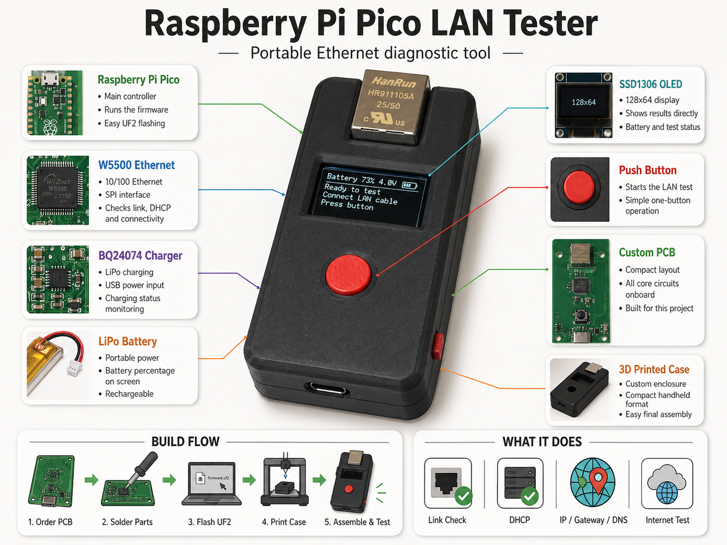
This is a compact handheld LAN tester based on a Raspberry Pi Pico, a W5500 Ethernet controller, an SSD1306 OLED display and LiPo battery charging.

It quickly checks whether an Ethernet port is actually working. The tester checks the physical link, requests an IP address with DHCP, shows IP / gateway / DNS information and performs a simple internet connectivity test.


Main Features

  • W5500 Ethernet controller over SPI
  • SSD1306 128x64 OLED display
  • One-button LAN test
  • Link, DHCP and internet check
  • IP / Gateway / DNS display
  • Battery voltage and charging status
  • Custom PCB with Raspberry Pi Pico
  • 3D printed enclosure

Project Files

The repository contains the firmware and KiCad hardware files:

text
LANTester/
├── Code/
└── KiCad/

Code contains the Raspberry Pi Pico firmware.
KiCad contains the schematic, PCB and manufacturing files.


Flashing

If the ready-built LANTester.uf2 file is included, flashing is simple:

  1. Hold BOOTSEL on the Raspberry Pi Pico.
  2. Plug it into USB.
  3. Copy LANTester.uf2 to the Pico drive.
  4. The Pico reboots and starts the firmware.

No special programmer is needed.


Full Build Guide

Instructables:
https://www.instructables.com/Portable-Raspberry-Pi-Pico-LAN-Tester/


3D Printed Case

Printables:
https://www.printables.com/model/1705220-raspberry-pi-pico-lan-tester


Notes

This repository contains the firmware and hardware files for the project.
Photos, build steps and assembly instructions are documented in the Instructables guide.

Parts

51
QtyValueFootprintReferences
8100nFCapacitor_SMD:C_0402_1005MetricC5, C6, C7, C8, C9, C10, C11, C13
64u7FCapacitor_SMD:C_0805_2012MetricC1, C2, C3, C4, C12, C14
449R9Capacitor_SMD:C_0603_1608MetricR10, R11, R12, R13
4MountingHoleMountingHole:MountingHole_3.5mmH1, H2, H3, H4
310kCapacitor_SMD:C_0603_1608MetricR3, R15, R16
215pFCapacitor_SMD:C_0603_1608MetricC15, C16
21k5Capacitor_SMD:C_0603_1608MetricR4, R5
2330RCapacitor_SMD:C_0603_1608MetricR7, R8
25k1Capacitor_SMD:C_0603_1608MetricR1, R2
26n8FCapacitor_SMD:C_0603_1608MetricC17, C18
110RCapacitor_SMD:C_0603_1608MetricR14
110nFCapacitor_SMD:C_0603_1608MetricC19
112k4Capacitor_SMD:C_0603_1608MetricR6
11nF/2kVCapacitor_SMD:C_1206_3216MetricC21
122nFCapacitor_SMD:C_0603_1608MetricC20
125MHzCrystal:Crystal_SMD_3225-4Pin_3.2x2.5mmY1
1BQ24074RGTPackage_DFN_QFN:VQFN-16-1EP_3x3mm_P0.5mm_EP1.6x1.6mmU1
1Battery_ConnectorMyFootprints:JST_PH_S2B-PH-SM4-TB_1x02-1MP_P2.00mm_HorizontalJ2
1MSK12C02MyFootprints:SW_MSK12C02S1
1RJ45_Hanrun_HR911105A_HorizontalConnector_RJ:RJ45_Hanrun_HR911105A_HorizontalJ3
1RaspberryPi_PicoModule:RaspberryPi_Pico_SMDA1
1SS14Diode_SMD:D_SMAD1
1SSD1306_ConnectorConnector_PinHeader_2.54mm:PinHeader_1x04_P2.54mm_VerticalJ4
1SW_PushButton_Switch_THT:SW_PUSH_6mm_H4.3mmSW1
1USB-CMyFootprints:SHOU HAN TYPE-C 16PIN 2MD(073)J1
1W5500Package_QFP:LQFP-48_7x7mm_P0.5mmU2

Questions

How big is the LAN Tester PCB?

It measures 34 × 80 mm and has 4 copper layers, 1.6 mm thick.

What parts does the LAN Tester use?

51 parts, built around the BQ24074RGTR, W5500, MSK12C02 and SS14. The full list of its parts is on this page, with links to each part's symbol and footprint where PCBKit's library has them.

Where can I download the LAN Tester KiCad files?

From the Markuselectronics/Raspberry-Pi-Pico-LAN-Tester repository on GitHub, at the commit this page was made from: the board is KiCad/LAN_Tester.kicad_pcb and its schematic KiCad/LAN_Tester.kicad_sch. PCBKit opens the board in the browser, with nothing to install.

Can I use the LAN Tester design in my own project?

Its repository states no licence, so its author keeps all rights: ask Markuselectronics before reusing the design.

Similar boards

  • 2 layers229.7 × 135.6 mmMorse mesh v2, the printed circuit board in 3D

    Morse mesh v2

    eihli/morse-mesh

    This is the current hardware source for future Morse Mesh revisions. It is a professionally reviewed redraw of the frozen, fabricated v1 board, not a pin-compatible replacement: notably, KEYIN moved from v1 PA0 to v2…

    75 parts1
  • 2 layersOpenchess controller, the printed circuit board in 3D

    Openchess controller

    PaoloJN/openchess

    A chessboard that knows where the pieces are: 64 Hall sensors, 81 RGB LEDs, one ESP32, a printed case, and a BLE phone app. KiCad hardware, PlatformIO firmware, Expo app.

    67 parts1
  • 2 layers95 × 147.3 mmBadge, the printed circuit board in 3D

    Badge

    hackthenorth/badge-hardware

    KiCAD Files for the 2026 Hacker Badge

    124 parts4
  • 2 layers30 × 30 mmMicro drone(esp32 s3 xiao), the printed circuit board in 3D

    Micro drone(esp32 s3 xiao)

    aryaman2050/Micro_ESP_Drone

    A compact micro brushed drone featuring an ESP32-based flight controller, a custom-designed 2-layer PCB, and Wi-Fi-based control.

    67 parts
  • 2 layers89.6 × 116.3 mmHackerBadgePCBV2, the printed circuit board in 3D

    HackerBadgePCBV2

    hackclub/OnBoard

    💡 Join 1,000 teenagers and make your first PCB with a $100 grant!

    31 parts915
  • 2 layers97.1 × 97.1 mmESP32 IMU Module V1.1, the printed circuit board in 3D

    ESP32 IMU Module V1.1

    shaun-lloyd/dev-ardupilot-obal

    ArduPi is an open hardware Raspberry Pi hat to run Ardupilot.

    87 parts2CC0-1.0
  • 2 layers48 × 38 mmRAMS RevC, the printed circuit board in 3D

    RAMS RevC

    JanClyde05/Road-Accident-Monitoring-System

    This directory contains the planning, specification, and initial KiCad project for RAMS Wearable PCB Revision C. Do not fabricate from this directory yet -- manual schematic wiring and DRC verification are still needed.

    68 parts1
  • 4 layers72.6 × 170 mmOpenJBOD RP2040, the printed circuit board in 3D

    OpenJBOD RP2040

    OpenJBOD/rp2040

    This repository contains the hardware design files OpenJBOD RP2040 Baseboard.

    129 parts87CERN-OHL-P-2.0