4 layers60 × 30 mm

 marksdude/Pikne1
A modular and repairable power bank
LiPo charger Rev 1.0 is an open-source printed circuit board by marksdude, from the marksdude/Pikne repository on GitHub. It is a 2-layer board of 72 × 26.7 mm with 117 parts on 104 nets, routed with 551 tracks and 127 vias.
It is built around the TPS55288RPMR, ISOM8111DFGR and TVS2200DRV, with the AO3400A and FFC2B35-06-G among its other parts. Its parts include 48 resistors, 33 capacitors, 10 transistors, 9 ICs and 6 connectors. It belongs with the power boards and the STM32 boards of this library.


A modular and repairable power bank
 Picture of rev 1.0 nonworking build

Core functionality comes from the TPS25751 and BQ25792 combination.
The TPS25751 is a USB-C PD controller IC. It handles PD negotiations, manages the BQ25792 and also has integrated I2C control for the BQ25792, which simplified firmware development.
The BQ25792 is a battery charger IC with support for USB-C PD output. It charges the battery and generates higher voltages (9V, 12V, 15V, 20V) for the USB C PD output. For 5V there is a separate regulator.
For example, if you connect a device you want to charge, first your device negotiates its required voltage and current with the TPS25751. Then the TPS25751 asks the BQ25792 to generate the requested voltage if it is above 5V. Once the correct voltage is available, the TPS25751 enables the output and your device starts charging.
An ATmega328P acts as the main controller. It monitors everything, handles faults, displays battery information and communicates with the modules.
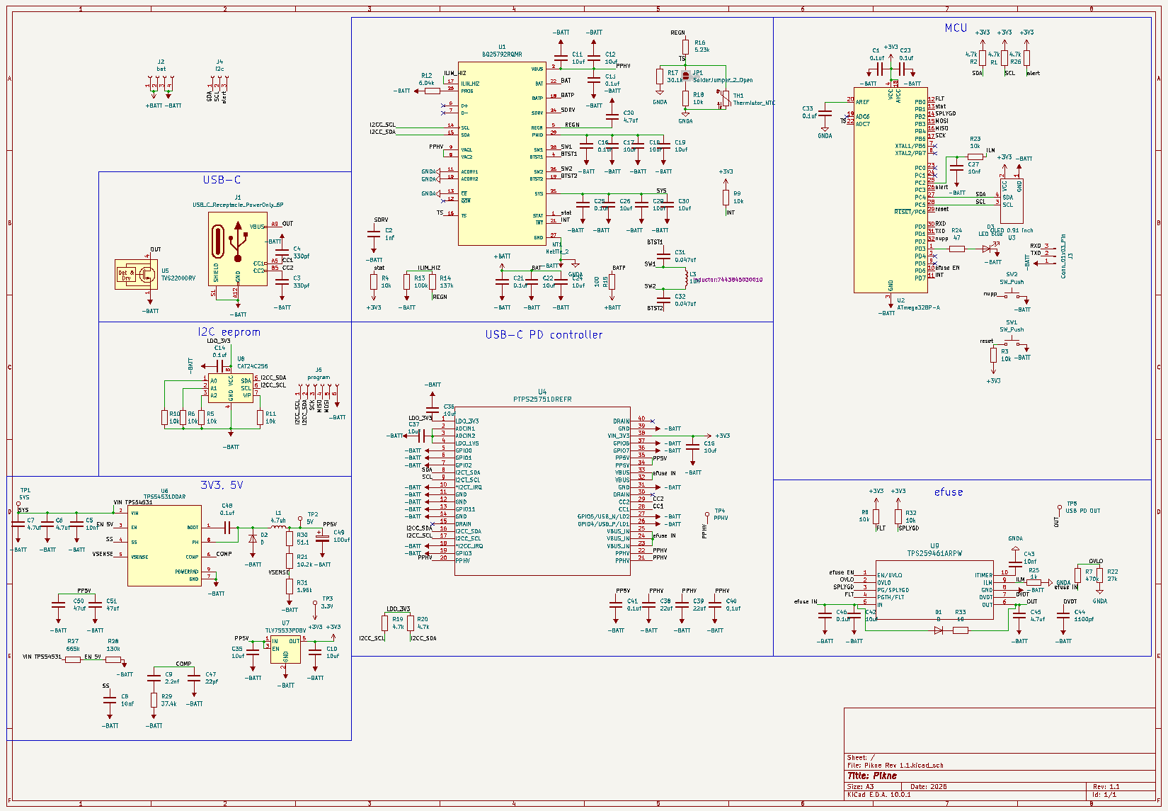
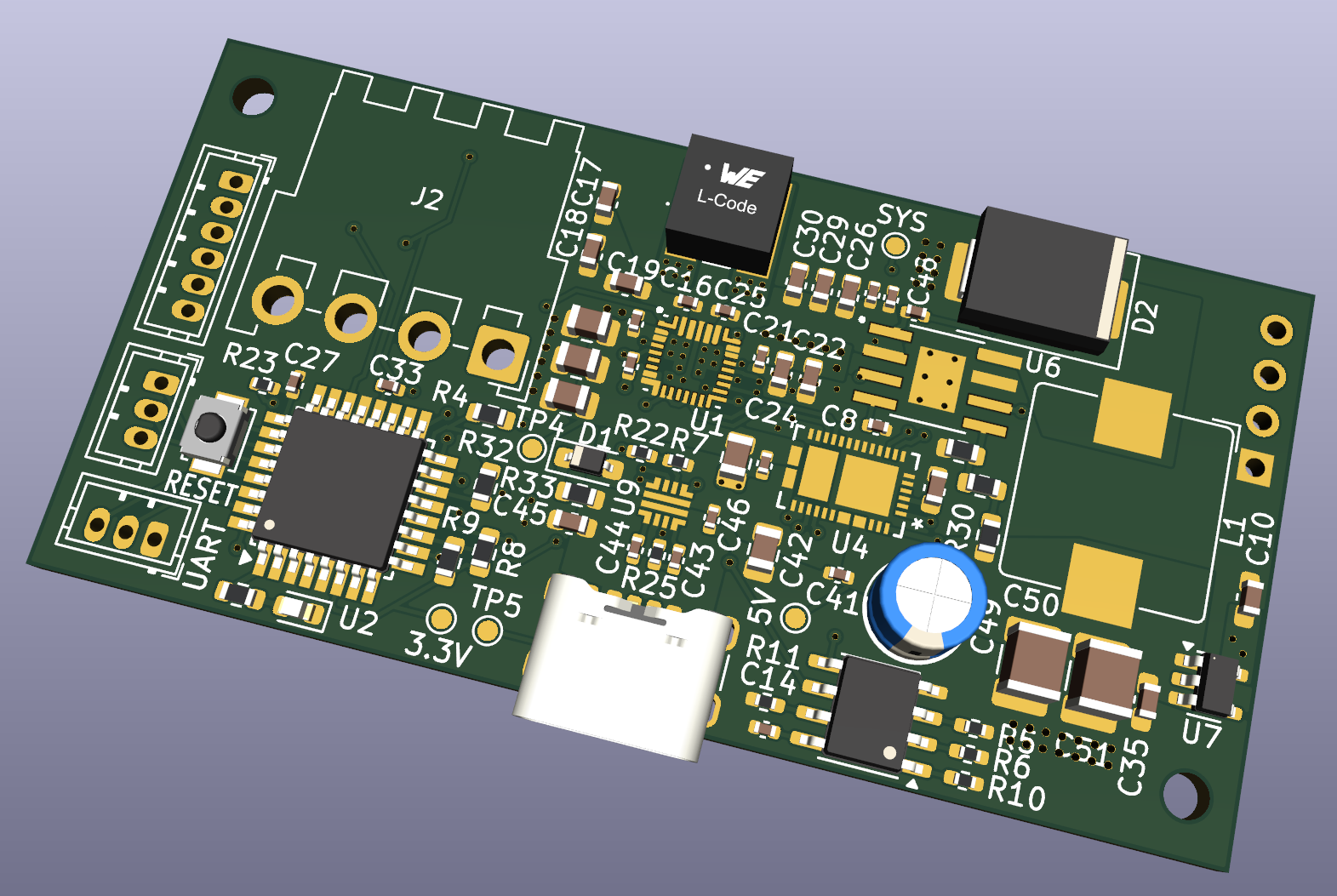
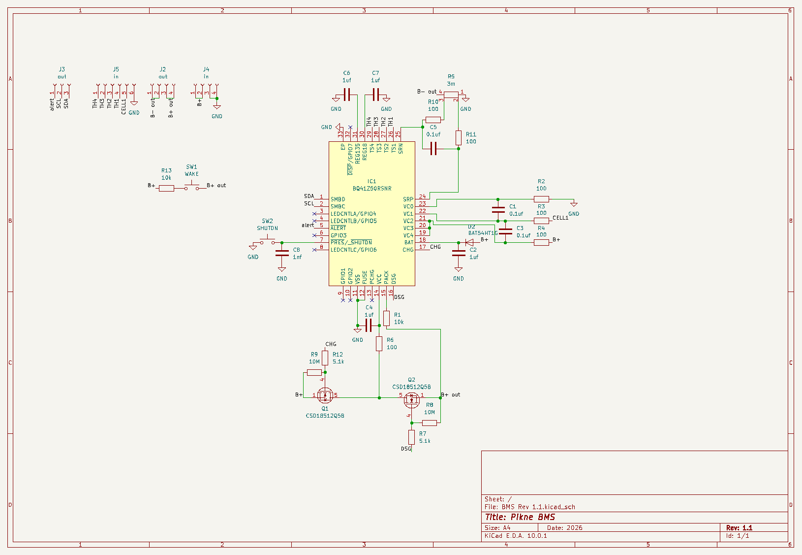
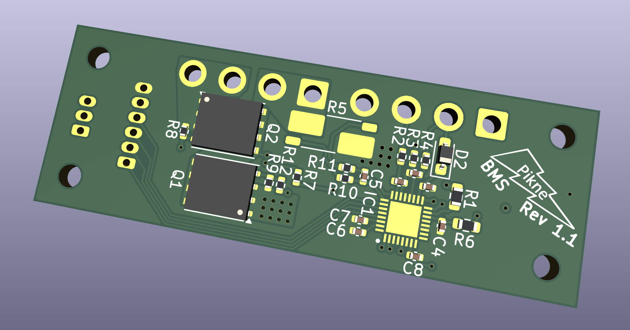
Modules can communicate with the power bank over UART through the pogo pins above the USB-C port. A connected module is idendified with an ID number sent by the module (1 for LED controller, 2 for Flashlight). The module can then request battery information or use the button on the power bank for additional control.
The LED controller is based on an ESP32-C3-WROOM-02U that is running ESPHome. There are 3 external MOSFETs that are used for the two monochrome outputs and one RGB output. An RGB output needs three MOSFETs, one for each color channel. Since there are only three, the monochrome outputs have to be connected together with two of the RGB channels. This is why the monochrome and RGB outputs can't be used simultaneously. INA219s are used for monitoring power draw of each output.
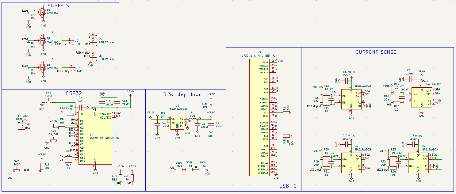
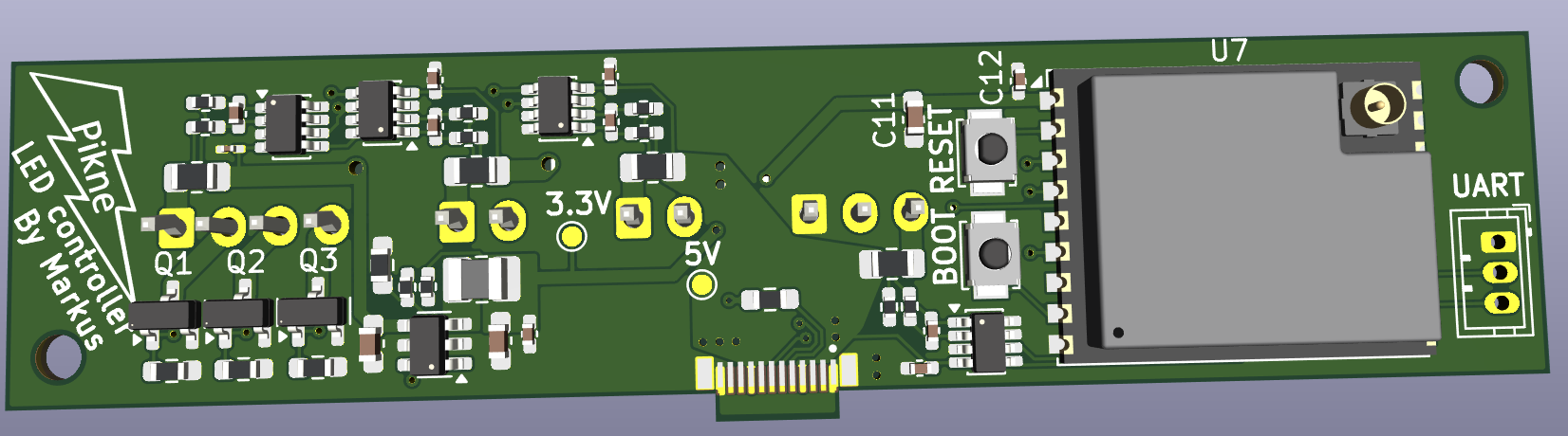
All of the smaller connectors are JST-ZH, while the battery connectors are JST-VH.
The main PCB has 4 connectors. One goes to the pogo connector, two to the BMS and one is for programming.

On the BMS two connectors go to the main PCB and two to the battery pack.

The battery is connected in a 2S2P configuration. There are cutouts in the bottom of the battery holder for routing the wires and for the thermistors. BAT+ and BAT- connect to the BMS input, thermistors and the balance lead connect to the BMS battery sense connector.
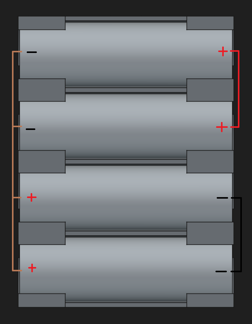
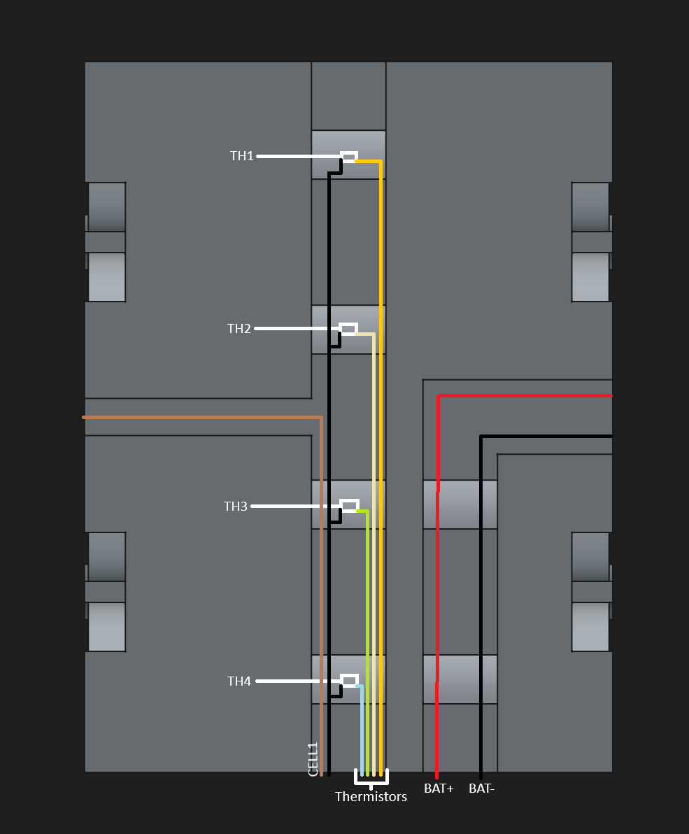
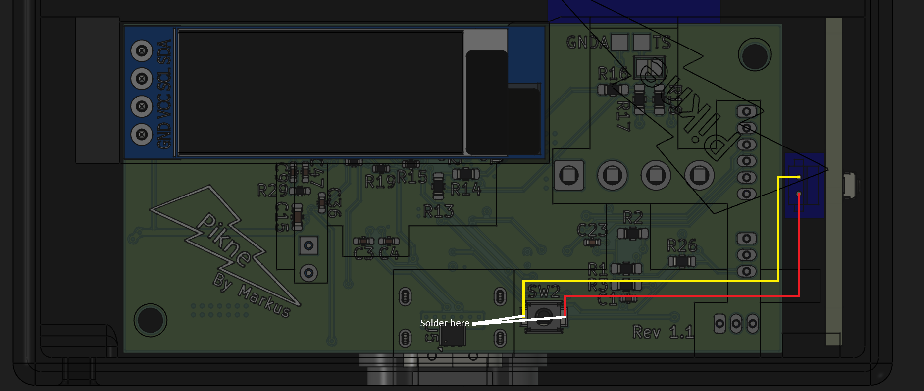
The button has to be soldered to the main PCB. The pogo connector is connected to the main PCB.
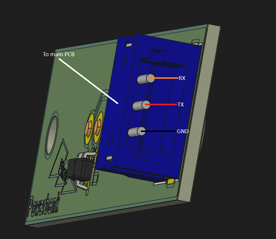
Not much wiring to do here just connect the pogo connector to the PCB.
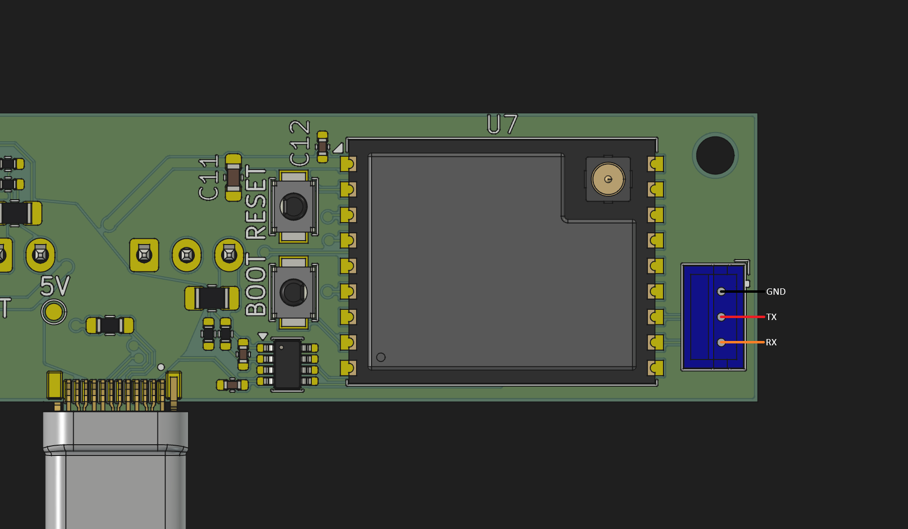
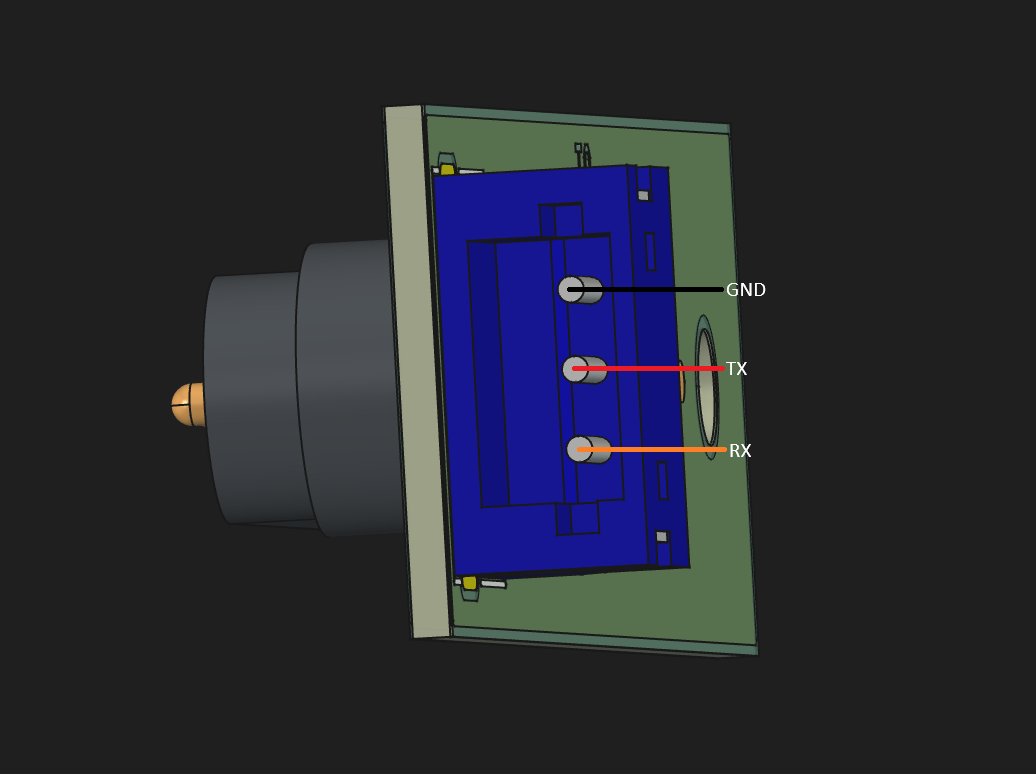
Output pinout:

Firmware is currently very limited. Version 0.1 has a basic menu to check some battery information, that's about it. It relies on the ArduinoSMBus library for communicating with the BMS and the Adafruit_SSD1306 and Adafruit GFX Library libraries for drawing on the OLED. I plan to move away from these libraries in the future.
There is still a lot left to be implemented.
It all started because I was tired of changing the AA batteries in my mom's battery-powered lights. I wanted to make the process faster and less wasteful, so I thought it would be a good idea to design an easily removable, rechargeable battery pack for the lights and also integrate them with Home Assistant. The original idea was going to have 2 parts the battery pack and a controller board. They were supposed to be held together with magnets, connected with pogo pins and communicate over UART. Then I thought, why not turn the battery pack into a power bank so it could be used for things other than the lights? That's what I did. The idea of making the battery pack easily removable led me to make the power bank modular. That's how Pikne was born.
| Qty | Value | Footprint | References |
|---|---|---|---|
| 12 | 0.1uf | Capacitor_SMD:C_0402_1005Metric | C4, C5, C6, C7, C12, C13, C20, C23, C26, C30, C31, C33 |
| 5 | 100k | Resistor_SMD:R_0603_1608Metric | R15, R16, R17, R18, R38 |
| 5 | 10k | Resistor_SMD:R_0402_1005Metric | R1, R6, R24, R28, R40 |
| 5 | AO3400A | Package_TO_SOT_SMD:SOT-23 | Q1, Q2, Q5, Q6, Q9 |
| 4 | 10uf | Capacitor_SMD:C_1206_3216Metric | C1, C2, C3, C8 |
| 4 | 1k | Resistor_SMD:R_0402_1005Metric | R9, R10, R11, R12 |
| 4 | 22k | Resistor_SMD:R_0402_1005Metric | R20, R21, R22, R23 |
| 4 | 22uf | Capacitor_SMD:C_1206_3216Metric | C11, C14, C15, C16 |
| 4 | 50 | Resistor_SMD:R_0603_1608Metric | R2, R13, R25, R30 |
| 3 | 10k | Resistor_SMD:R_0603_1608Metric | R31, R34, R35 |
| 3 | 10uf | Capacitor_SMD:C_0603_1608Metric | C22, C27, C29 |
| 3 | 1uf | Capacitor_SMD:C_0603_1608Metric | C17, C18, C24 |
| 3 | 220 | Resistor_SMD:R_0603_1608Metric | R5, R19, R27 |
| 3 | 4.7k | Resistor_SMD:R_0603_1608Metric | R42, R43, R44 |
| 3 | 430 | Resistor_SMD:R_0603_1608Metric | R3, R14, R26 |
| 3 | DMP3014SFDE-13 | MOSFET:DMP1022UFDEQ7 | Q7, Q8, Q10 |
| 3 | ISOM8111DFGR | SOP254P700X240-4N:SOP254P700X240-4N | IC1, IC3, IC4 |
| 3 | TestPoint | TestPoint:TestPoint_Pad_D1.0mm | TP1, TP2, TP3 |
| 2 | 1uf | Capacitor_SMD:C_0402_1005Metric | C19, C21 |
| 2 | NTTFS5C454NLTAG | MOSFET:WDFN8_3.3X3.3_0.65P_CASE_511AB_ISSUE_D_1 | Q3, Q4 |
| 1 | 0.1uf | Resistor_SMD:R_0402_1005Metric | C25 |
| 1 | 100 | Resistor_SMD:R_0402_1005Metric | R41 |
| 1 | 100 | Resistor_SMD:R_0603_1608Metric | R33 |
| 1 | 100k | Resistor_SMD:R_0402_1005Metric | R46 |
| 1 | 10m | Resistor_SMD:R_1206_3216Metric | R32 |
| 1 | 135k | Resistor_SMD:R_0402_1005Metric | R48 |
| 1 | 150k | Resistor_SMD:R_0402_1005Metric | R29 |
| 1 | 1k | Resistor_SMD:R_0603_1608Metric | R37 |
| 1 | 200pf | Capacitor_SMD:C_0402_1005Metric | C9 |
| 1 | 20k | Resistor_SMD:R_0603_1608Metric | R8 |
| 1 | 22k | Resistor_SMD:R_0603_1608Metric | R39 |
| 1 | 22uf | Capacitor_SMD:C_0805_2012Metric | C28 |
| 1 | 3.3uh | Inductor:INDC3225X120N | L2 |
| 1 | 30k | Resistor_SMD:R_0402_1005Metric | R45 |
| 1 | 4.7uf | Capacitor_SMD:C_0603_1608Metric | C10 |
| 1 | 4.7uh | Inductor_SMD:L_Bourns_SRP1038C_10.0x10.0mm | L1 |
| 1 | 470 | Resistor_SMD:R_0402_1005Metric | R36 |
| 1 | 47pf | Capacitor_SMD:C_0201_0603Metric | C32 |
| 1 | 49.9k | Resistor_SMD:R_0402_1005Metric | R7 |
| 1 | 50k | Resistor_SMD:R_0402_1005Metric | R47 |
| 1 | 6.19k | Resistor_SMD:R_0603_1608Metric | R4 |
| 1 | Battery | Connector_JST:JST_VH_B2P-VH-B_1x02_P3.96mm_Vertical | J1 |
| 1 | Conn_01x04_Socket | Connector_JST:JST_ZH_B4B-ZR_1x04_P1.50mm_Vertical | J6 |
| 1 | Conn_01x05_Socket | Connector_JST:JST_XH_S5B-XH-A_1x05_P2.50mm_Horizontal | J2 |
| 1 | D_Schottky | Diode_SMD:D_SOD-323_HandSoldering | D2 |
| 1 | D_Zener | Diode_SMD:D_SOD-323_HandSoldering | D1 |
| 1 | ER_OLEDM0.91_1x-I2C | Display:ER_OLEDM0.91_1x-I2C | U3 |
| 1 | FFC2B35-06-G | FFC2B3506G:FFC2B3506G | J4 |
| 1 | NetTie_2 | NetTie:NetTie-2_SMD_Pad0.5mm | NT1 |
| 1 | STM32L011G3Ux | Package_DFN_QFN:QFN-28_4x4mm_P0.5mm | U4 |
| 1 | STUSB4500QTR | Package_DFN_QFN:QFN-24-1EP_4x4mm_P0.5mm_EP2.7x2.7mm | U2 |
| 1 | SW_Push | Button_Switch_SMD:SW_SPST_B3U-1000P | SW1 |
| 1 | TPS55288RPMR | buck_boost:TPS55288RPMR | IC2 |
| 1 | TPS562246DRLR | SOTFL50P160X60-6N:SOTFL50P160X60-6N | U5 |
| 1 | TVS2200DRV | Package_SON:WSON-6-1EP_2x2mm_P0.65mm_EP1x1.6mm | U1 |
| 1 | UART | Connector_JST:JST_ZH_B3B-ZR_1x03_P1.50mm_Vertical | J5 |
| 1 | UP32-1-C-H-G-BMT-P24 | UP32-1-C-H-G-BMT-P24:SAMESKY_UP32-1-C-H-G-BMT-P24 | J3 |
The 115 most common of 117 parts.


gschuurman/android_vendor_gschuurman_vehicle_interfaces
vehicle interfaces for android automotive for a custom headunit


electro-practically/wled-controller
WLED ESP32 controller powered by USB-C Power Delivery.

8423/cryocooler-board
A 4-layer power and control board for a Ricor K508N cryocooler. It does two jobs, both controlled over I²C:

hydazz/iasis
An optional Raspberry Pi Compute Module 5 carrier for Iasis. It plugs into the main board's HubPD population and carries Ethernet, NVMe storage, an accessory USB-C port and a service USB-C port.

mikesmitty/power-manifold
Six-port USB-C power supply: up to 100 W per port from one 24 V supply, with per-port control, priority-based power sharing and Home Assistant support. 100% local, no cloud required.


byrantech/laptop
anyon_e, a highly integrated, high end, open source laptop. Attempt the impossible.
It measures 72 × 26.7 mm and has 2 copper layers, 0.8 mm thick.
117 parts, built around the TPS55288RPMR, ISOM8111DFGR, TVS2200DRV and AO3400A. The full list of its parts is on this page, with links to each part's symbol and footprint where PCBKit's library has them.
From the marksdude/Pikne repository on GitHub, at the commit this page was made from: the board is Modules/LiPo charger/PCB/LiPo charger Rev 1.0.kicad_pcb and its schematic BMS/BMS Rev 1.1.kicad_sch. PCBKit opens the board in the browser, with nothing to install.
Its repository states no licence, so its author keeps all rights: ask marksdude before reusing the design.