
2 layers9.5 × 22 mm
 marelab/OsmoIRSensor1
IR Water & Fluid detection Sensor based on ATTINY45
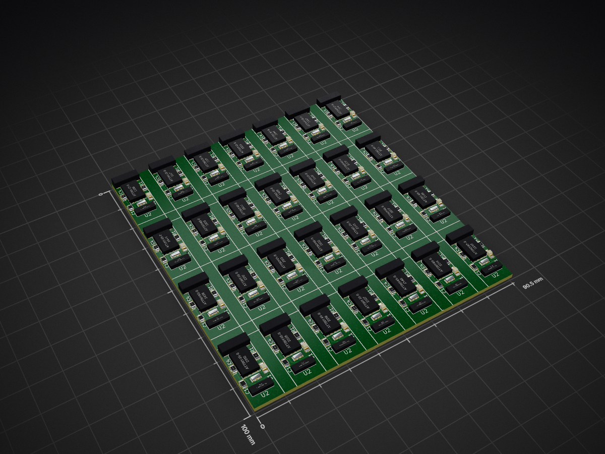
OsmoIRSensor5x5cm is an open-source printed circuit board by marelab, from the marelab/OsmoIRSensor repository on GitHub. It is a 2-layer board of 90.5 × 100 mm with 336 parts on 11 nets, routed with 2,744 tracks and 308 vias.
It is built around the TSOP75436WTR. Its parts include 112 resistors, 56 ICs, 56 diodes, 28 capacitors and 28 connectors. It belongs with the sensors and measurement boards and the AVR (ATmega, ATtiny) boards of this library.
OsmoIRSensor IR Water & Fluid detection Sensor based on ATTINY45.
The Sensor was designed for Osmosi waterlevel control. It is designed to be full encapsulated in a EPOXY case. The hole design an maufacturing process as well as the technical backgrounds for the IR detection is described under https://www.marelab.org
| Qty | Value | Footprint | References |
|---|---|---|---|
| 28 | 10K | Resistors_SMD:R_0805 | R4, R4, R4, R4, R4, R4, R4, R4, R4, R4, R4, R4, R4, R4, R4, R4 +12 |
| 28 | 20MHz | marelab:RESONATOR | X1, X1, X1, X1, X1, X1, X1, X1, X1, X1, X1, X1, X1, X1, X1, X1 +12 |
| 28 | 220R | Resistors_SMD:R_0805 | R1, R1, R1, R1, R1, R1, R1, R1, R1, R1, R1, R1, R1, R1, R1, R1 +12 |
| 28 | 22nF | Resistors_SMD:R_0805 | C1, C1, C1, C1, C1, C1, C1, C1, C1, C1, C1, C1, C1, C1, C1, C1 +12 |
| 28 | 422R | Resistors_SMD:R_0805 | R3, R3, R3, R3, R3, R3, R3, R3, R3, R3, R3, R3, R3, R3, R3, R3 +12 |
| 28 | 4K7 | Resistors_SMD:R_0805 | R2, R2, R2, R2, R2, R2, R2, R2, R2, R2, R2, R2, R2, R2, R2, R2 +12 |
| 28 | ATTINY45-S | marelab:SOIC-8 | U1, U1, U1, U1, U1, U1, U1, U1, U1, U1, U1, U1, U1, U1, U1, U1 +12 |
| 28 | CONN_02X03_PCB_DIRECT | marelab:CON3x2PCB | J2, J2, J2, J2, J2, J2, J2, J2, J2, J2, J2, J2, J2, J2, J2, J2 +12 |
| 28 | LED IR | LEDs:LED_PLCC-2 | D2, D2, D2, D2, D2, D2, D2, D2, D2, D2, D2, D2, D2, D2, D2, D2 +12 |
| 28 | LED PWR | LEDs:LED_0805 | D1, D1, D1, D1, D1, D1, D1, D1, D1, D1, D1, D1, D1, D1, D1, D1 +12 |
| 28 | LOGO | marelab:LOGO_OPENSOURCE | G***, G***, G***, G***, G***, G***, G***, G***, G***, G***, G***, G***, G***, G***, G***, G*** +12 |
| 28 | TSOP75436WTR | marelab:SMD-IR | U2, U2, U2, U2, U2, U2, U2, U2, U2, U2, U2, U2, U2, U2, U2, U2 +12 |

PantsForBirds/adsbee
Open Source Embedded ADS-B Receiver


BAL-ORX/RocSync
Millisecond-Accurate Temporal Synchronization for Heterogeneous Camera Systems


It measures 90.5 × 100 mm and has 2 copper layers, 1.6 mm thick.
336 parts, built around the TSOP75436WTR. The full list of its parts is on this page, with links to each part's symbol and footprint where PCBKit's library has them.
From the marelab/OsmoIRSensor repository on GitHub, at the commit this page was made from: the board is hardware/OsmoIRSensor5x5cm.kicad_pcb. PCBKit opens the board in the browser, with nothing to install.
Its repository states no licence, so its author keeps all rights: ask marelab before reusing the design.