
2 layers95 × 71 mm

 PantsForBirds/adsbee344
Open Source Embedded ADS-B Receiver
Panel proto tracking comparator board is an open-source printed circuit board by PantsForBirds, from the PantsForBirds/adsbee repository on GitHub, published under the GPL-3.0 licence. It is a 2-layer board of 68 × 45 mm with 336 parts on 168 nets, routed with 696 tracks and 0 vias.
Its parts include 96 resistors, 48 capacitors and 48 diodes. It belongs with the radio and wireless boards of this library.


ADSBee is a family of open-source, dual-band ADS-B receivers from Pants for Birds LLC. Every ADSBee decodes 1090 MHz Mode S / ADS-B and 978 MHz UAT transmissions onboard — no SDR dongle, FPGA, or host computer required — maintains an aircraft dictionary, and streams tracked aircraft over UART (and, on the 1090 family, WiFi / Ethernet) in a wide range of output protocols. This repository holds the firmware, hardware design files, datasheets, and host software for the whole family.
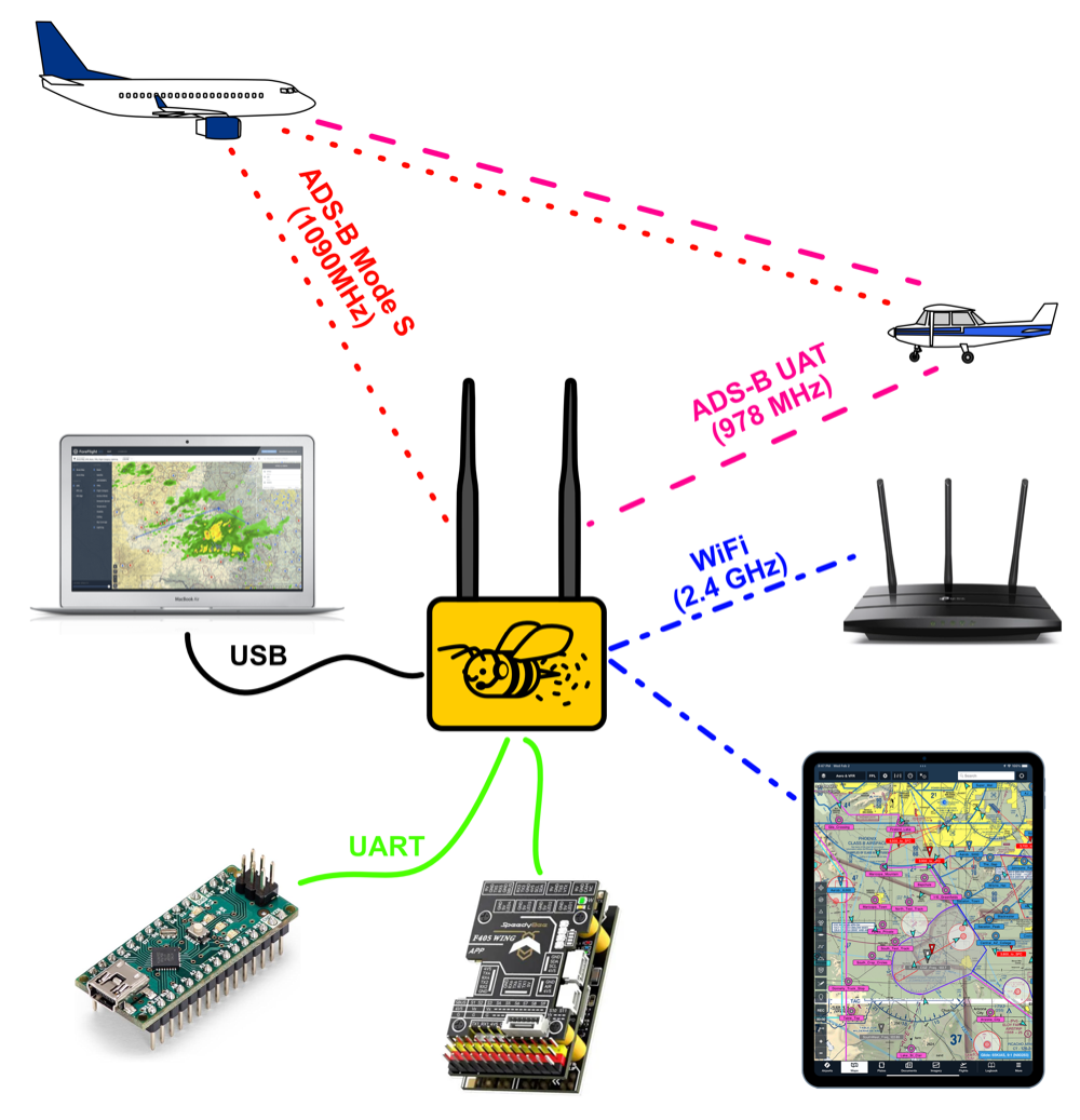
There are two product lines, which share most of their firmware (firmware/common/):
| ADSBee 1090 | ADSBee 1421 | |
|---|---|---|
| Best for | Ground stations, feeders, networked receivers | Ultra-low-power embedded / UAS detect-and-avoid |
| Processors | RP2040 + ESP32-S3 + CC1312 | TI CC1314R10 + Semtech LR2021 |
| 1090 MHz | Custom RF frontend + RP2040 PIO decoder | LR2021 OOK receiver |
| 978 MHz UAT | CC1312 sub-GHz radio | CC1314 sub-GHz radio (uplink reception selectable) |
| Interfaces | USB, UART, WiFi, Ethernet (PoE pant / W5500), GNSS | UART (AT commands), SYNC line, LR2021 SPI passthrough |
| Power | ~1W | ~19 mA at 1.8–3.3 V |
| Firmware | firmware/adsbee_1090/ | firmware/adsbee_1421/ |
We work hard to make ADSBee products performant and reliable, but not all aircraft broadcast their location, messages can be lost or corrupted, and hardware or software can fail. ADSBee cannot guarantee detection or accurate reporting of all traffic. Users are responsible for evaluating its suitability for their application and for the safe operation of any system it is integrated into. See our terms of sale and license for full terms.
All ADSBee devices are designed and sold by Pants for Birds LLC. Purchasing a device is the best way to support the project. Product pages, datasheets, and the Quick Start Guide live at pantsforbirds.com.
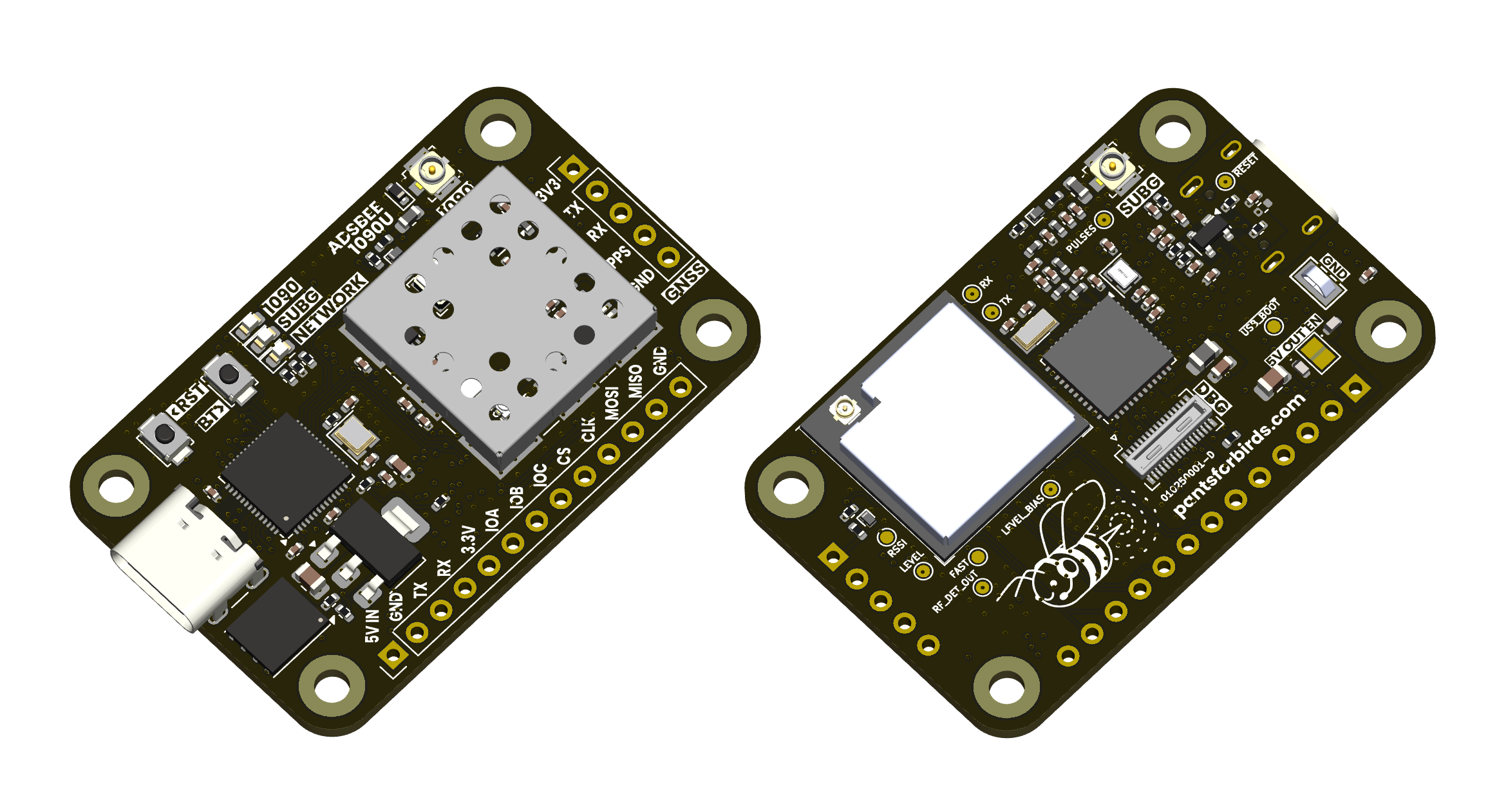 | ADSBee 1090U — RP2040, ESP32-S3, CC1312, and a custom 1090 MHz RF frontend on a single PCBA, enabling all multi-band receive and networking functions (Ethernet requires an external pant). Datasheet |
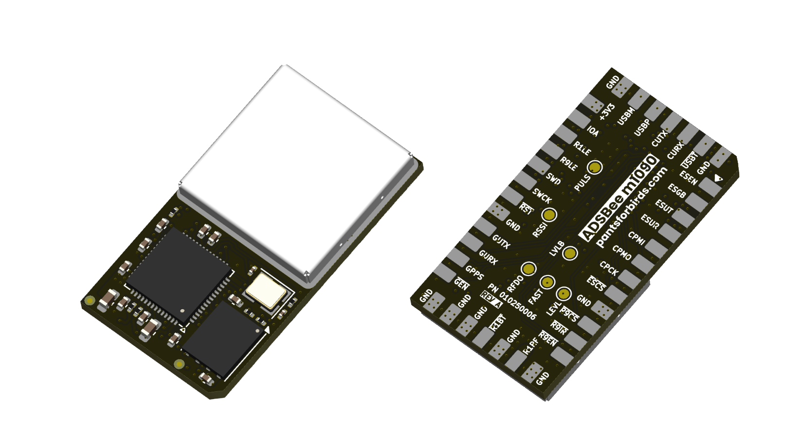 | ADSBee m1090 — solder-down module containing only the 1090 MHz frontend and RP2040. Add a CC1312 and ESP32 on your carrier board for the full 1090U feature set, running the same firmware image. Drops one of the 1090U's two LNA stages for lower power and better ultra-close-range performance; populate an external LNA on the carrier for equivalent maximum range. An m1090 Eval Board is available (datasheet). |
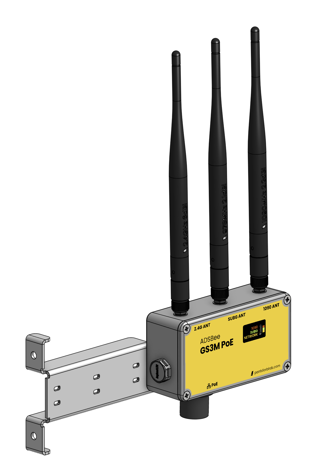 | GS3M PoE — the ADSBee 1090U in a ruggedized, weatherproof enclosure, connected and powered over 802.3af Power over Ethernet for industrial and outdoor installations. Datasheet |
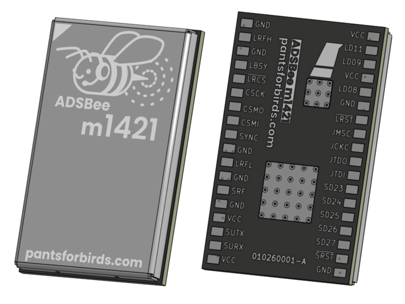 | ADSBee m1421 — high-performance, ultra-low-power dual-band receiver module (TI CC1314R10 + Semtech LR2021). Receives 1090 MHz Mode S and 978 MHz UAT, tracks up to 400 aircraft onboard, and reports over UART. Weighs 1.85 g. Datasheet |
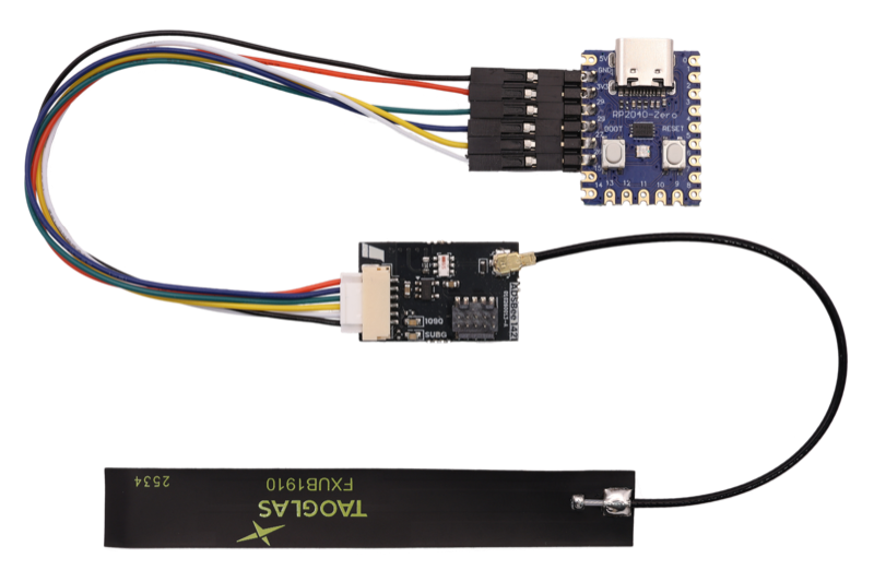 | ADSBee 1421 Developer Kit — compact carrier board for the m1421 with a power combiner so a single lightweight dual-band antenna feeds both the 1090 MHz and 978 MHz inputs. Includes the PCBA with ARM-JTAG header, wire harness, USB programmer, and a dual-band ADS-B antenna. Datasheet |
ADSBee 1090 is an open-source multi-band radio receiver and decoder for ADS-B packets transmitted by aircraft and ground stations. It is based on an RP2040 microcontroller and utilizes two independent PIO blocks to find and decode ADS-B messages without the need for an FPGA. ADSBee 1090 includes a radio receiver frontend with filtering and amplification, as well as a software-defined comparator circuit with an adjustable trigger threshold for customizable receive sensitivity in a diverse range of RF environments.
ADSBee 1090 utilizes some basic RF hardware (SAW filters, LNA, logarithmic power detector) to amplify the received pulse-position-modulated ADS-B waveform into a pulse train that is conditioned by a comparator and fed to a PIO input pin on the RP2040. The RP2040 utilizes two PIO state machines, one for preamble detection and one for Manchester decoding of the message body, to decode the ADS-B message. This offers significant cost and power savings over FPGA-based solutions that solve the same problem.
A filtered PWM output from the RP2040 can be used to adjust the bias of the data slicer comparator circuit on the output of the receive signal chain, allowing logarithmic adjustments in receiver sensitivity which can be used to filter out weaker ADS-B signals in congested environments or maximize sensitivity for increased receive range.
There are two devices connected to the RP2040 via a common SPI bus: a CC1312 for secondary band receive and an ESP32-S3 for networking functions.
The CC1312 can be tuned to a variety of sub-GHz frequencies to decode UAT messages (and potentially more protocols in the future). These messages are forwarded to the RP2040 over SPI and reported through a unified interface along with the Mode S packets received by the RP2040.
The ESP32-S3 ingests raw packets from the RP2040 and maintains its own aircraft dictionary for reporting over network interfaces (WiFi, Ethernet). The RP2040's dictionary holds 400 aircraft for its USB and UART outputs; the ESP32-S3's holds 200.
All three microcontrollers utilize code stored on the RP2040's external flash chip, so firmware updates are conducted by flashing a single firmware image to the RP2040, which in turn flashes updated firmware images to the CC1312 and ESP32-S3.
ADSBee 1421 is an ultra-low-power dual band ADS-B receiver, built around a TI CC1314R10 low-power RF MCU and a Semtech LR2021 radio. The LR2021 provides best-in-class sensitivity for the high-baud-rate OOK 1090 MHz Mode S waveform, while the CC1314's sub-GHz RF core receives 978 MHz UAT and its Cortex-M33 does all demodulation, FEC, decoding, and aircraft tracking. The whole receiver draws about 19 mA and weighs under 2 g, making it suited to UAS detect-and-avoid and other power- and weight-constrained applications.
AT+R1090_PREAMBLE).AT+SUBG_MODE=UAT_RX_NO_UPLINK) to save airtime and CPU when only traffic is needed.The CC1314R10 runs a NoRTOS super-loop: it polls the LR2021 over SPI for 1090 MHz OOK frames, services its own RF core's UAT receptions (ADS-B and uplink are distinguished by sync word, so uplink can be switched off at the radio), runs the shared Mode S / UAT decoders and aircraft dictionary from firmware/common/, and reports over the console UART. A host can suspend the device by driving SYNC high; on wake the receiver re-initializes itself. SYNC is also the ROM bootloader backdoor pin, so a reset while SYNC is high enters the serial bootloader. See firmware/adsbee_1421/AGENTS.md for the build guide and the SYNC sleep / LR2021 bus-handoff contract, and the m1421 datasheet for the full AT command reference.
| Path | Contents |
|---|---|
firmware/ | All firmware. adsbee_1090/ (RP2040 pico/, esp/, CC1312 ti/), adsbee_1421/ (CC1314 ti/, RP2040-Zero programmer/, the ADSBee 1421 Programmer), common/ (shared decoders, aircraft dictionary, comms, settings), modules/ (submodules: cppAT, googletest, …), scripts/ (dev tooling), build.sh dispatcher. |
software/ | Host software: adsbee_1421_console/ (single-file Web Serial console + UART flasher for the 1421), adsbee/ (Python package), serial_logger/, and tar1090/ / ultrafeeder/ / ultra2/ feeder compose files. |
ci/ | Hardware-in-the-loop USB/UF2 + OTA flash test run by the self-hosted CI runner. |
kicad/ | Hardware design files (ADSBee 1090, 1090U, frontend prototypes, panels). |
3d/ | Enclosure exports and CAD links. |
ltspice/, excel/ | RF / analog simulations and design calculations. |
affinity/ | Diagrams and promotional artwork sources. |
word/ | Product datasheets and firmware reference guide (.docx sources, PDFs in word/exports/). |
references/ | Protocol specifications and component datasheets. |
images/ | Images used by this README. |
All toolchains live in Docker containers, so the only host requirements are Docker and git.
git clone https://github.com/CoolNamesAllTaken/adsbee.git
cd adsbee
bash firmware/scripts/setup_dev.sh        # init submodules + install the pre-commit version-check hook
bash firmware/build.sh adsbee_1090        # RP2040 + ESP32-S3 + CC1312 -> combined.uf2
bash firmware/build.sh adsbee_1421        # CC1314R10 -> adsbee_1421-<version>.hex
firmware/README.md — prerequisites, the build dispatcher, build targets and outputs.firmware/AGENTS.md — firmware architecture overview and the version-management rules.firmware/adsbee_1090/Developers_Guide.md covers the three-processor build order, flashing (combined.uf2 over USB BOOTSEL, or OTA through the ESP32 web interface), and recovery.firmware/adsbee_1421/AGENTS.md covers the build; flash over JTAG with a J-Link (firmware/adsbee_1421/ti/README.md), or over UART using the ROM bootloader (SYNC bootloader backdoor) via the ADSBee 1421 Programmer (an RP2040-Zero board included in the Developer Kit), a host script driving RTS/DTR, or the Upload Firmware button in the web console.Prebuilt firmware is published on the Releases page. Releases are tagged per product as adsbee_1090-<major>.<minor>.<patch> and adsbee_1421-<major>.<minor>.<patch> (release candidates carry an -rcN suffix). AT+DEVICE_INFO? reports the firmware version running on a device.
word/exports/ (AT command reference, reporting protocols, pinouts).AT+DEVICE_INFO? (part code and firmware version);AT+LOG_LEVEL=INFO makes the device chattier) and, for the 1090 family, the web interface/feed configuration involved.Contributions are welcome (bug fixes, new output protocols, decoder improvements, documentation, etc)! Please follow the steps below to contribute a change.
main.bash firmware/scripts/setup_dev.sh once. It initializes submodules and installs a git pre-commit hook that enforces the version rule below.firmware/adsbee_1090/, firmware/adsbee_1421/, or firmware/common/ must ship under a firmware version that has not been released yet for the affected product(s) (firmware/common/coprocessor/object_dictionary.cpp for 1090, firmware/adsbee_1421/ti/object_dictionary/object_dictionary.cpp for 1421; a common/ change concerns both). If main is already on the next unreleased RC, keep it; if its version matches a release tag, move to the next unreleased RC. Note that devices only reflash coprocessors on a version mismatch, so you will need to force a reflash or bump the software version to test your code firmware/AGENTS.md. When have finished testing and go to you submit your PR, ensure that your firmware version matches the version string in main! Firmware versions are only rolled upon each release.word/.firmware/build.sh and, for 1090 changes, run the host unit tests (bash firmware/build.sh adsbee_1090 test).main. CI builds every target and runs the unit tests; the hardware-in-the-loop flash test runs on main after merge.By contributing you agree that your contributions are licensed under the GPL-3.0.
ADSBee firmware, software, and design files in this repository are released under the GNU General Public License v3.0. ADSBee is a product of Pants for Birds LLC.
| Qty | Value | Footprint | References |
|---|---|---|---|
| 144 | TestPoint | TestPoint:TestPoint_Pad_1.0x1.0mm | TP1, TP1, TP1, TP1, TP1, TP1, TP1, TP1, TP1, TP1, TP1, TP1, TP1, TP1, TP1, TP1 +128 |
| 48 | 100k | Resistor_SMD:R_0603_1608Metric | R2, R2, R2, R2, R2, R2, R2, R2, R2, R2, R2, R2, R2, R2, R2, R2 +32 |
| 48 | D_Schottky | Custom_Diode:D_0402_1005Metric | D1, D1, D1, D1, D1, D1, D1, D1, D1, D1, D1, D1, D1, D1, D1, D1 +32 |
| 24 | 0.1uF | Capacitor_SMD:C_0603_1608Metric | C1, C1, C1, C1, C1, C1, C1, C1, C1, C1, C1, C1, C1, C1, C1, C1 +8 |
| 24 | 10k | Resistor_SMD:R_0603_1608Metric | R1, R1, R1, R1, R1, R1, R1, R1, R1, R1, R1, R1, R1, R1, R1, R1 +8 |
| 24 | 1nF | Capacitor_SMD:C_0603_1608Metric | C3, C3, C3, C3, C3, C3, C3, C3, C3, C3, C3, C3, C3, C3, C3, C3 +8 |
| 24 | 200k | Resistor_SMD:R_0603_1608Metric | R7, R7, R7, R7, R7, R7, R7, R7, R7, R7, R7, R7, R7, R7, R7, R7 +8 |

PantsForBirds/adsbee
Open Source Embedded ADS-B Receiver


PantsForBirds/adsbee
Open Source Embedded ADS-B Receiver


PantsForBirds/adsbee
Open Source Embedded ADS-B Receiver


BAL-ORX/RocSync
Millisecond-Accurate Temporal Synchronization for Heterogeneous Camera Systems


It measures 68 × 45 mm and has 2 copper layers, 1.6 mm thick.
336 parts. The full list of its parts is on this page, with links to each part's symbol and footprint where PCBKit's library has them.
From the PantsForBirds/adsbee repository on GitHub, at the commit this page was made from: the board is kicad/prototyping/panel_proto_tracking_comparator_board/panel_proto_tracking_comparator_board.kicad_pcb and its schematic kicad/prototyping/panel_proto_data_slicer_board/panel_proto_data_slicer_board.kicad_sch. PCBKit opens the board in the browser, with nothing to install.
Its repository publishes it under the GPL-3.0 licence: you may reuse it on that licence's terms (keep the author's notice, and for a copyleft licence share your changes alike).