Compact 8-layer ESP32 robot controller with 4 independent brushed DC motor drivers, onboard power regulation, battery monitoring and expansion GPIO. Designed for RC cars, mobile robots and combat robotics.
Robot aio esp32 manuel solder 8 layer is an open-source printed circuit board by manyetox, from the manyetox/ESP32-Robot-AIO-Controller repository on GitHub. It is an 8-layer board of 50 × 46.2 mm with 59 parts on 58 nets, routed with 443 tracks and 63 vias.
It is built around the ESP32-WROOM-32UE-N4 and TPS56528DDA. Its parts include 24 capacitors, 14 resistors, 6 connectors, 2 ICs and 1 inductor. It belongs with the robots and motor control and power boards and the ESP32 boards of this library.
Compact all-in-one ESP32 controller for RC cars, mobile robots and small combat robots.
This PCB was designed to replace the usual collection of an ESP32 development board, multiple motor-driver modules, voltage regulators and large amounts of wiring with a single compact controller.
The board integrates an ESP32-WROOM-32UE, four independent brushed DC motor drivers, onboard power regulation, battery-voltage monitoring, programming/debug connections and additional GPIO into a 50 × 46.2 mm PCB.
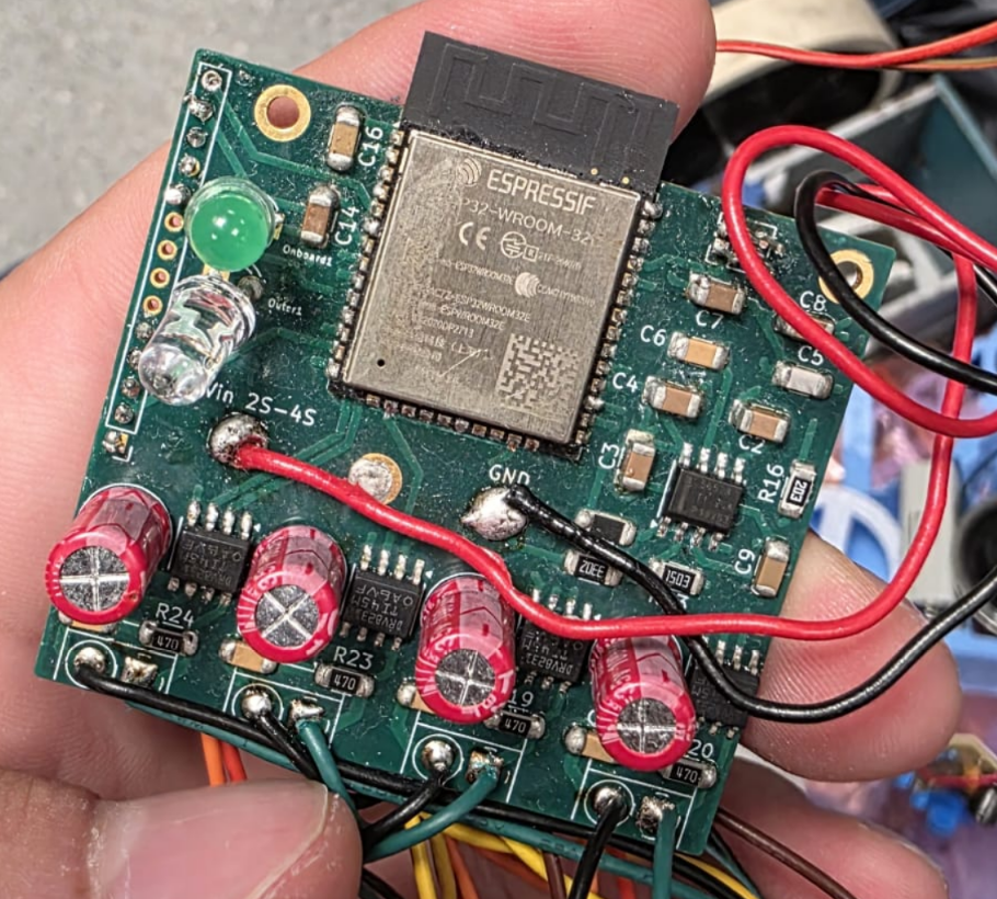
The controller has been manufactured, hand-assembled and fully tested, and the finished board is operational.
Status: Hardware tested and working
PCB: 8-layer, 50 × 46.2 mm
Controller: ESP32-WROOM-32UE
Motor channels: 4 × bidirectional brushed DC
Battery: 2S–4S
Application: RC cars, mobile robots and small combat robots
Why I Built This
Small competition robots often end up containing several separate modules:
ESP32/Arduino development board
multiple H-bridge motor drivers
voltage regulator
battery-monitoring circuit
programming hardware
connectors
large amounts of point-to-point wiring
This works, but it takes space, adds failure points and makes the electrical system much harder to package cleanly inside a small robot.
The goal of Robot AIO was to integrate the essential electronics of a small mobile robot onto one board.
It was originally designed with Robot Wars / combat robotics and RC-car projects in mind, where compact packaging, fast assembly and simple motor control are particularly useful.
Hardware Images
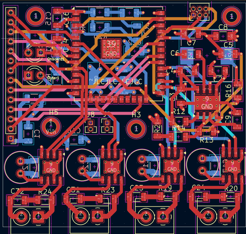
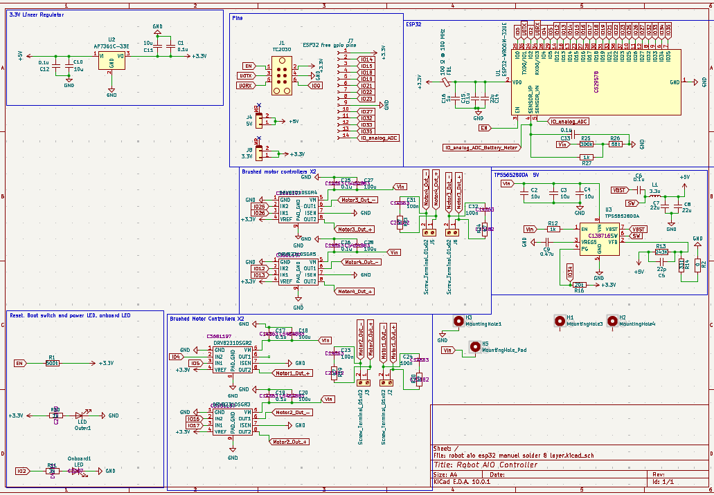
The final PCB shown above has been assembled and tested successfully. The repository also includes the design views below.
PCB Layout
Schematic
A demonstration video is not currently included in this repository. To add
one later, place it in the Media directory and link it here.
Features
4 Independent Brushed Motor Channels
The board contains four DRV8231 H-bridge motor-driver stages.
Each channel supports:
forward rotation
reverse rotation
PWM speed control
active braking
independent ESP32 control
This makes the board suitable for configurations such as:
2-wheel differential drive
4-wheel differential drive
skid-steer robots
mecanum/omnidirectional platforms
RC vehicles
small combat robots
other multi-motor robotic platforms
Each motor has its own 2-pin screw terminal.
ESP32 Controller
The main processor is an:
ESP32-WROOM-32UE
This provides:
dual-core ESP32 processing
Wi-Fi
Bluetooth
hardware PWM
ADC
UART
SPI
I²C
additional GPIO for sensors and peripherals
The 32UE variant also allows an external antenna to be used, which is useful when the controller is mounted inside a robot with significant metal structure around it.
Possible control methods therefore include:
Bluetooth gamepads
phone control
custom wireless controllers
Wi-Fi control
conventional RC receiver interfaces
autonomous control
The exact control system is implemented in firmware rather than being locked into the PCB.
The motor drivers operate directly from the battery rail while the ESP32 and logic circuitry are supplied by the regulated 3.3 V rail.
Motor GPIO Mapping
The four motor drivers are controlled directly by ESP32 GPIO.
Motor
Input 1
Input 2
Output Connector
Motor 1
GPIO 4
GPIO 5
J2
Motor 2
GPIO 16
GPIO 17
J3
Motor 3
GPIO 25
GPIO 26
J6
Motor 4
GPIO 12
GPIO 13
J5
Each channel can therefore be independently controlled using the ESP32 PWM peripherals.
For differential-drive robots, for example:
text
Left Motors  → Motor 1 + Motor 2
Right Motors → Motor 3 + Motor 4
The assignment can of course be changed entirely in firmware.
Motor Outputs
Each motor channel uses a DRV8231 integrated H-bridge.
The DRV8231 includes:
integrated N-channel MOSFET H-bridge
PWM control
over-current protection
thermal protection
under-voltage lockout
current regulation capability
The IC is rated for up to 3.7 A peak output current.
Important: 3.7 A is the motor-driver IC's peak rating, not a guaranteed continuous-current rating for the complete PCB. Practical continuous current depends on motor load, PCB temperature, cooling, battery voltage and operating conditions.
Always check the stall current of the motor rather than only its no-load/running current.
Motor Noise Suppression
Brushed motors can generate significant electrical noise from commutation.
Each motor output therefore includes an RC suppression network consisting of approximately:
text
47 Ω + 100 nF
across the motor output.
This helps suppress high-frequency switching and brush noise before it propagates through the rest of the robot electronics.
Additional suppression directly across the motor terminals may still be useful for particularly noisy motors.
Power System
Battery Input
The PCB was designed for:
2S–4S battery systems
Typical LiPo voltage range:
Battery
Nominal
Fully Charged
2S
7.4 V
8.4 V
3S
11.1 V
12.6 V
4S
14.8 V
16.8 V
Large solder pads are provided for the main:
text
VIN
GND
connections.
This avoids passing the combined robot current through a small PCB connector.
3.3 V Regulator
The logic power supply is based around a TPS56528 synchronous buck regulator.
It converts the battery voltage directly to approximately:
text
3.3 V
for the ESP32 and logic circuitry.
The regulator allows the controller to operate directly from the robot battery without requiring a separate external buck converter.
Battery Voltage Monitoring
Battery voltage is measured directly by the ESP32 through an onboard resistor divider.
The divider uses approximately:
text
300 kΩ
56 kΩ
with filtering before the ADC input.
The approximate relationship is:
text
Vbattery ≈ Vadc × 6.36
For example:
text
ADC = 2.00 V
Battery ≈ 12.7 V
This allows firmware to implement features such as:
live battery telemetry
low-voltage warnings
reduced-power mode
automatic shutdown behaviour
battery percentage estimation
The battery-monitor ADC input is connected internally to the ESP32.
Because the ESP32 ADC is not a precision measurement device, calibration against a multimeter is recommended when accurate voltage readings are required.
Expansion Header
A 14-pin 2.00 mm expansion header exposes unused ESP32 connections.
Pin
Signal
1
3.3 V
2
GPIO 14
3
GPIO 15
4
GPIO 18
5
GPIO 19
6
GPIO 21
7
GPIO 22
8
GPIO 23
9
GND
10
GPIO 27
11
GPIO 32
12
GPIO 33
13
GPIO 35
14
Analog ADC
This makes it possible to add peripherals without modifying the controller PCB.
Examples include:
IMUs
encoders
distance sensors
servos
limit switches
LEDs
current sensors
RC receivers
displays
SPI devices
I²C devices
Programming Interface
A dedicated programming/debug header provides:
text
EN
3.3 V
UART TX
GND
UART RX
GPIO 0
This allows the ESP32 to be programmed without permanently adding a USB-to-UART converter to the robot.
Keeping the USB interface off the main board saves both PCB space and components in the finished robot.
LEDs
The PCB includes two LED functions.
Power LED
One LED is connected to the 3.3 V supply and provides a visual indication that the logic rail is powered.
Programmable LED
A second LED is controlled by:
text
GPIO 2
It can be used for:
boot indication
connection status
controller pairing
low-battery warning
fault indication
debugging
PCB
The controller uses an 8-layer PCB.
Dimensions:
text
50.0 mm × 46.2 mm
PCB thickness:
text
1.6 mm
The board includes multiple mounting holes and large ground/power areas to make mechanical installation into a robot easier.
The design was also intentionally created around components that could be assembled manually, allowing prototypes to be built without requiring professional PCBA.
Example Applications
RC Car
A basic RC vehicle can use:
text
Gamepad / Phone
       │
   Bluetooth
       │
       ▼
     ESP32
     ┌──┴──┐
     ▼     ▼
 Left    Right
Motor    Motor
No external motor-driver module or microcontroller board is required.
Four-Wheel Drive Robot
All four channels can be used independently:
text
Motor 1 ─ Front Left
Motor 2 ─ Rear Left
Motor 3 ─ Front Right
Motor 4 ─ Rear Right
This is particularly useful for compact skid-steer robots.
Combat Robot
For a small combat robot, the board can combine:
wireless control
drive-motor control
battery monitoring
status indication
sensor interfaces
into a single PCB.
High-current weapon motors should normally use a separate appropriately rated ESC or motor controller.
Design Goals
The project was built around several priorities:
Compact
Replace several separate modules with one board.
Simple Wiring
Battery, motors and peripherals connect directly to the controller.
Flexible
The ESP32 allows the same PCB to be used for many different robot architectures.
Repairable
The first prototypes were designed with manual assembly and debugging in mind.
Competition Friendly
The controller is intended for robots where space, weight, reliability and fast repair are important.
Tested Hardware
The manufactured prototype has been assembled and tested successfully.
Verified functionality includes the core controller hardware, power system and motor-control architecture.
How big is the Robot aio esp32 manuel solder 8 layer PCB?
It measures 50 × 46.2 mm and has 8 copper layers, 1.6 mm thick.
What parts does the Robot aio esp32 manuel solder 8 layer use?
59 parts, built around the ESP32-WROOM-32UE-N4 and TPS56528DDA. The full list of its parts is on this page, with links to each part's symbol and footprint where PCBKit's library has them.
Where can I download the Robot aio esp32 manuel solder 8 layer KiCad files?
From the manyetox/ESP32-Robot-AIO-Controller repository on GitHub, at the commit this page was made from: the board is Hardware/robot aio esp32/robot aio esp32 manuel solder 8 layer.kicad_pcb and its schematic Hardware/robot aio esp32/robot aio esp32 manuel solder 8 layer.kicad_sch. PCBKit opens the board in the browser, with nothing to install.
Can I use the Robot aio esp32 manuel solder 8 layer design in my own project?
Its repository states no licence, so its author keeps all rights: ask manyetox before reusing the design.
Source-available modular mobile carrier for autonomous photonics experiments using ESP32 control, optical flow, IMU sensing and magnetic wheel encoding.
AMR Hardware & PCB Design: Low-level controller board and hardware system (STM32 / KiCad) engineered as the foundation for future ROS 2, SLAM, and autonomous navigation integration.
Working on designing the impeller and auger portion of the snowblower. Switched from using a worm gear assembly to a custom ring and pinion setup using a spiral bevel gear.
Power management board that converts a 4S Li-ion battery into multiple regulated voltage rails using integrated DC-DC converters, with built-in protection against overvoltage, overcurrent, and reverse polarity.