2 layers27.9 × 16.5 mm

 manula5454/Tomato-Tick
idk yet
Tomato Tick is an open-source printed circuit board by manula5454, from the manula5454/Tomato-Tick repository on GitHub, published under the MIT licence. It is a 2-layer board of 97.2 × 146.9 mm with 18 parts on 54 nets, routed with 145 tracks and 7 vias.
Its parts include 7 resistors, 6 diodes, 1 IC, 1 transistor and 1 connector. It belongs with the RP2350 boards of this library.
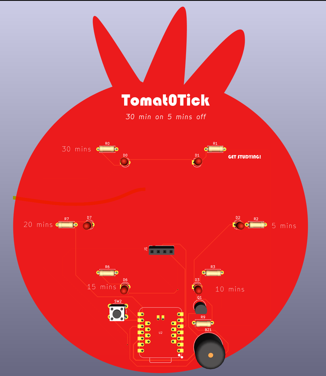
A PCB in the shape of a Tomato that runs a pomodoro timer of 30 minutes studying and 5 minutes break on repeat.
Here is the final render of my project!!
Libraries :
#include <Wire.h>
#include <Adafruit_GFX.h>
#include <Adafruit_SSD1306.h>
(Can all be found inside the IDE library )
void(displayStudytime) -- Displays remaining study time on OLED screen void(displayBreaktime) -- Displays remaining study time on OLED
buttonPin -- 1 press = pause, long press = reset {rp.2040 reboot();}
LED functions - builds up (e.g. LED5 lights up, then LED4....)

| Reference | Part | Qty | Description | Vendor | Unit Price | Link |
|---|---|---|---|---|---|---|
| U2 | XIAO RP2350 | 1 | Microcontroller module | Seeed Studio | $5.90 | https://seeedstudio.com |
| D0 D1 D2 D3 D6 D7 | LED 3mm | 6 | Countdown LEDs | Core Electronics | $0.60 | https://core-electronics.com.au |
| R0 R1 R2 R3 R6 R7 | 330R resistor | 6 | LED current-limit resistors | Core Electronics | $1.58 | https://core-electronics.com.au |
| R9 | 1k resistor | 1 | Transistor base resistor | N/A | N/A | Have one at home |
| Q1 | 2N3904 transistor | 1 | NPN transistor for the buzzer | Core Electronics | $0.30 | https://core-electronics.com.au |
| SW2 | 6mm tactile button | 1 | Pause and reset button | Core Electronics | $0.36 | https://core-electronics.com.au |
| BZ1 | 5V active buzzer | 1 | Alert buzzer | Core Electronics | $0.27 | https://core-electronics.com.au |
| J1 | 1x4 pin header | 1 | OLED connector | Core Electronics | $0.11 | https://core-electronics.com.au |
| U1 | 1x7 pin header | 2 | Microcontroller connector | Core Electronics | $1.26 | https://core-electronics.com.au |
| OLED1 | White I2C OLED display (SSD1306) | 1 | 0.96in display | Core Electronics | $5.05 | https://core-electronics.com.au |
| Shipping & GST Cost | $5.99 | |||||
| Total Cost | $25.63 |
| Qty | Value | Footprint | References |
|---|---|---|---|
| 6 | 330R | Resistor_THT:R_Axial_DIN0207_L6.3mm_D2.5mm_P7.62mm_Horizontal | R0, R1, R2, R3, R6, R7 |
| 6 | LED | LED_THT:LED_D3.0mm | D0, D1, D2, D3, D6, D7 |
| 1 | 1K | Resistor_THT:R_Axial_DIN0207_L6.3mm_D2.5mm_P7.62mm_Horizontal | R9 |
| 1 | 2N3904 | Package_TO_SOT_THT:TO-92_Inline | Q1 |
| 1 | Buzzer | Buzzer_Beeper:Buzzer_12x9.5RM7.6 | BZ1 |
| 1 | Conn_01x04_Pin | Connector_PinSocket_2.54mm:PinSocket_1x04_P2.54mm_Vertical | J1 |
| 1 | SW_Push | Button_Switch_THT:SW_PUSH_6mm | SW2 |
| 1 | XIAO-RP2350-DIP | Seeed_Studio_XIAO_Series:XIAO-RP2350-DIP | U2 |

VoronDesign/Voron-Hardware
Cool Hardware designed by the Voron Design group


hackclub/OnBoard
💡 Join 1,000 teenagers and make your first PCB with a $100 grant!

VoronDesign/Voron-Tap
Tap is a nozzle-based z-probe for the V2 and Trident printer designs. The entire toolhead moves to trigger an optical switch. Tap offers many advantages:

Luos-io/luos_engine
Open-source and real-time orchestrator for cyber-physical-systems, to easily design, test and deploy embedded applications and digital twins.


Twotoz/C5VRX
Ultra-minimal, zero-CPU 5.8 GHz analog FPV video receiver using ESP32-C5 Wi-Fi 6 PHY MODEM_DIAG, BitScrambler WBFM demodulation & resistor DAC CVBS
It measures 97.2 × 146.9 mm and has 2 copper layers, 1.6 mm thick.
18 parts. The full list of its parts is on this page, with links to each part's symbol and footprint where PCBKit's library has them.
From the manula5454/Tomato-Tick repository on GitHub, at the commit this page was made from: the board is PCB/TomatoTick.kicad_pcb and its schematic PCB/TomatoTick.kicad_sch. PCBKit opens the board in the browser, with nothing to install.
Its repository publishes it under the MIT licence: you may reuse it on that licence's terms (keep the author's notice, and for a copyleft licence share your changes alike).