
2 layers76.4 × 63.3 mm
InfraRedGelUniversalDispenser
abdontroche/InfraRed_Gel_Universal_Dispenser
This project pretends to be a open source device that could help people fighting against the COVID-19.
20 parts5CC0-1.0
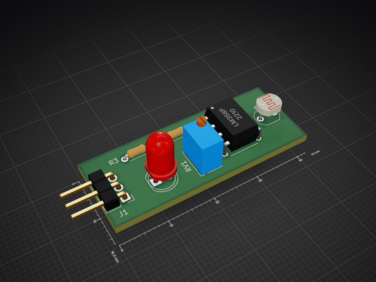
 Manideep136/Light-Sensor
This project is a Light Sensor circuit based on an LDR (Light Dependent Resistor) and an operational amplifier.
Light Sensor is an open-source printed circuit board by Manideep136, from the Manideep136/Light-Sensor repository on GitHub. It is a 2-layer board of 42 × 16.4 mm with 7 parts on 9 nets, routed with 41 tracks and 0 vias.
It is built around the LM358P. Its parts include 3 resistors, 1 IC, 1 diode and 1 connector. It belongs with the sensors and measurement boards of this library.
This project is a Light Sensor circuit based on an LDR (Light Dependent Resistor) and an operational amplifier.
The circuit detects changes in the surrounding light intensity using an LDR. The changing resistance of the LDR is converted into a voltage variation, which is then processed by the op-amp circuit.
The schematic and PCB were designed using KiCad.
An LDR (Light Dependent Resistor) changes its resistance depending on the amount of light falling on it.
The LDR is combined with a resistor to form a voltage divider. The voltage produced by this divider changes according to the surrounding light level.
This changing voltage is supplied to the op-amp circuit, which processes the signal and provides the required output.
| Component | Purpose |
|---|---|
| LDR | Detects surrounding light intensity |
| Op-Amp | Processes and compares the sensor voltage |
| Resistors | Voltage division and biasing |
| Capacitors | Filtering and signal stability |
| Potentiometer | Adjusts the detection threshold |
| Connectors | Power and output connections |
The main parts of the circuit are:
The PCB was designed using KiCad.
The design process includes:
LDR-Light-Sensor/
│
├── doc/
│   ├── Schematic.png
│   ├── Layout.png
│   └── 3D_View.png
│
├── gerber/
│   ├── *.gbr
│   └── *.drl
│
├── LDR Light Sensor.kicad_pro
├── LDR Light Sensor.kicad_sch
├── LDR Light Sensor.kicad_pcb
│
└── README.md| Qty | Value | Footprint | References |
|---|---|---|---|
| 1 | 10k | Resistor_THT:R_Axial_DIN0204_L3.6mm_D1.6mm_P5.08mm_Horizontal | R1 |
| 1 | 200k | Potentiometer_THT:Potentiometer_Bourns_3266W_Vertical | RV1 |
| 1 | 330 | Resistor_THT:R_Axial_DIN0204_L3.6mm_D1.6mm_P5.08mm_Horizontal | R3 |
| 1 | Conn_01x03_Pin | Connector_PinHeader_2.54mm:PinHeader_1x03_P2.54mm_Horizontal | J1 |
| 1 | LDR07 | OptoDevice:R_LDR_5.1x4.3mm_P3.4mm_Vertical | R2 |
| 1 | LED | LED_THT:LED_D5.0mm | D1 |
| 1 | LM358P | LM358P:DIP794W45P254L959H508Q8 | U1 |
abdontroche/InfraRed_Gel_Universal_Dispenser
This project pretends to be a open source device that could help people fighting against the COVID-19.

igorzab-stud/wanptek_encoder
Digital front-panel mod for Wanptek DC power supplies — replaces analog potentiometers with dual rotary encoders, MCP4725 DACs, and an OLED display.

ansh1113/e-bike-conversion-kit
A 4-layer PCB-based e-bike conversion kit featuring an STM32-based VESC ESC, power management circuits, wireless throttle, GSM, GPS, and more.


UAA-F14/PCBs-Design
Power electronics PCB coursework — SCR controller, buck converter, Class D amplifier, DC-AC inverter, and a protected power supply Resources

asliwaa/ECG-Simulator
A custom hardware ECG/EKG simulator built with the XIAO ESP32-C6 and an MCP4725 DAC, designed to generate physiologically accurate heart signals.


IKGB105/PCBs-POWER-ELECTRONICS
Power electronics PCB coursework — SCR controller, buck converter, Class D amplifier, DC-AC inverter, and a protected power supply Resources
It measures 42 × 16.4 mm and has 2 copper layers, 1.6 mm thick.
7 parts, built around the LM358P. The full list of its parts is on this page, with links to each part's symbol and footprint where PCBKit's library has them.
From the Manideep136/Light-Sensor repository on GitHub, at the commit this page was made from: the board is Light sensor/Light sensor.kicad_pcb and its schematic Light sensor/Light sensor.kicad_sch. PCBKit opens the board in the browser, with nothing to install.
Its repository states no licence, so its author keeps all rights: ask Manideep136 before reusing the design.