2 layers60 × 30 mm
Controller
google/mozc-devices
Circuit diagrams and firmware source code for Gboard DIY keyboards
11 parts3kApache-2.0
 Manideep136/Bridge-Rectifier
This project is a Bridge Rectifier PCB designed using KiCad. The circuit converts an AC input voltage into DC output voltage using four diodes connected in a bridge configuration.
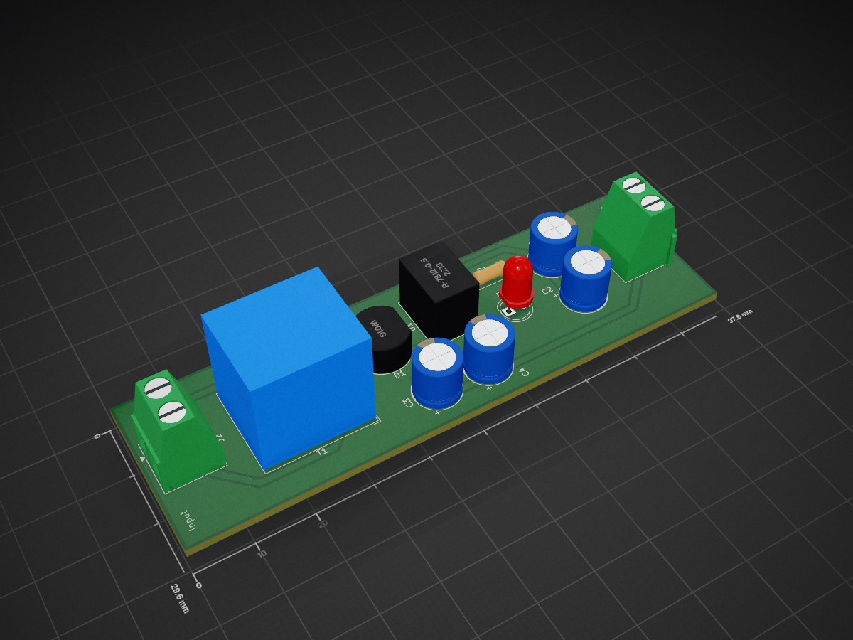
Bridge Rectifire is an open-source printed circuit board by Manideep136, from the Manideep136/Bridge-Rectifier repository on GitHub. It is a 2-layer board of 97.6 × 29.6 mm with 11 parts on 8 nets, routed with 55 tracks and 0 vias.
Its parts include 4 capacitors, 2 diodes, 2 connectors, 1 resistor and 1 IC. It belongs with the interfaces and adapters boards of this library.
📌 Project Overview
This project is a Bridge Rectifier PCB designed using KiCad. The circuit converts an AC input voltage into DC output voltage using four diodes connected in a bridge configuration.
A bridge rectifier is one of the most commonly used circuits in power supplies because it uses both the positive and negative half cycles of the AC input to produce a pulsating DC output.
The PCB was designed in KiCad, including the schematic, footprint assignment, PCB layout, routing, and 3D visualization.
🎯 Objectives Design a bridge rectifier circuit. Convert AC voltage into DC voltage. Understand the working of four-diode bridge rectification. Design the schematic in KiCad. Assign appropriate footprints to components. Create and route the PCB. Perform ERC and DRC checks. Visualize the final PCB using KiCad 3D Viewer. ⚙️ Working Principle
The bridge rectifier consists of four diodes (D1, D2, D3, and D4) connected in a bridge arrangement.
During the positive half cycle of the AC input, two diodes conduct and current flows through the load in one direction.
During the negative half cycle, the other two diodes conduct. Even though the AC input polarity reverses, the current through the load continues in the same direction.
Therefore, both halves of the AC waveform are converted into a pulsating DC waveform.
Basic Operation + DC │ │ ┌────┴────┐ │ │ D1 D2 │ │ AC IN ~ ──┤ ├── ~ AC IN │ │ D3 D4 │ │ └────┬────┘ │ - DC 🔌 Input and Output AC Input
The AC input is connected to the two terminals marked:
AC ~ AC ~ DC Output
The rectified output is available at:
The output can be connected to a load or a filter capacitor depending on the application.
🧩 Components Used Reference Component Quantity D1 Rectifier Diode 1 D2 Rectifier Diode 1 D3 Rectifier Diode 1 D4 Rectifier Diode 1 J1 AC Input Connector 1 J2 DC Output Connector 1
The exact diode part number and connector type depend on the physical components selected for the PCB.
📐 PCB Design
The PCB was designed using KiCad.
The design workflow was:
Create the bridge rectifier schematic. Add the four rectifier diodes. Add AC input and DC output connectors. Connect all components according to the bridge rectifier circuit. Assign footprints. Transfer the schematic to PCB Editor. Arrange the components. Route the PCB tracks. Check clearances and connections. Run ERC and DRC. Inspect the PCB using the 3D Viewer. 🖥️ KiCad Files
The project contains the following main files:
Bridge-Rectifier/ │ ├── Bridge-Rectifier.kicad_pro ├── Bridge-Rectifier.kicad_sch ├── Bridge-Rectifier.kicad_pcb ├── README.md │ └── Images/ ├── schematic.png ├── pcb_layout.png └── 3d_view.png File Description File Description .kicad_pro KiCad project configuration .kicad_sch Circuit schematic .kicad_pcb PCB layout and routing README.md Project documentation Images/ Schematic, PCB and 3D-view images 🔄 Rectification Process
The AC waveform contains both positive and negative half cycles.
AC Input
/ \ /
/ \ /
-----/--------/----------
/ \ /
Bridge Rectifier Output
After rectification, both halves appear in the same direction:
   / \       / \
  /   \     /   \
-----/--------/----------
The negative half cycle is flipped to the positive side.
The resulting waveform is called full-wave pulsating DC.
🔋 Adding a Filter Capacitor
A capacitor can be connected across the DC output to reduce ripple.
      + DC
        │
        ├───────┐
        │       │
       C1      LOAD
        │       │
        └───────┘
        │
      - DC
The capacitor charges when the rectified voltage increases and discharges through the load when the voltage decreases.
This produces a smoother DC output.
📊 Advantages Uses both half cycles of the AC input. Higher efficiency compared with a half-wave rectifier. Produces a higher average DC output. Lower ripple frequency is easier to filter. Simple and reliable circuit. Widely used in DC power supplies. ⚠️ Important Considerations
Before manufacturing or powering the PCB:
Check the diode voltage rating. Check the diode current rating. Verify diode orientation. Use connectors suitable for the expected current. If using an electrolytic capacitor, verify its polarity. Ensure the capacitor voltage rating is higher than the maximum expected DC voltage. Verify PCB track width for the expected current. ⚠️ Safety
Do not connect this beginner PCB directly to 230 V AC mains.
For testing, use a safe, isolated, low-voltage AC source, such as the secondary side of an appropriately rated transformer.
If the PCB is ever intended for mains voltage, the design must include appropriate creepage/clearance, insulation, fusing, enclosure, connector ratings, and other safety requirements.
🧪 Testing Procedure Inspect the PCB for solder bridges and incorrect connections. Check the orientation of all four diodes. Check the AC input terminals. Check the positive and negative DC output terminals. Verify the PCB tracks using the KiCad schematic. Use a multimeter to check for unintended shorts. Apply a safe low-voltage AC input. Measure the DC voltage at the output. If a capacitor is installed, check its polarity and voltage rating. ✅ KiCad Checks
Before manufacturing the PCB:
ERC – Electrical Rules Check
Run ERC in the schematic editor to identify problems such as:
Unconnected pins Incorrect connections Power-related warnings Missing connections DRC – Design Rules Check
Run DRC in the PCB Editor to check:
Track clearance Unconnected nets Track width Copper spacing Board-edge clearance Other PCB design-rule violations 🚀 Future Improvements
This bridge rectifier PCB can be extended into a complete DC power supply by adding:
Filter capacitor Voltage regulator such as 7805 LED power indicator Fuse Reverse-polarity protection Screw terminals Adjustable voltage regulator Test points Additional filtering Example Power Supply AC Input │ ▼ Bridge Rectifier │ ▼ Filter Capacitor │ ▼ Voltage Regulator │ ▼ Regulated DC Output 📚 Learning Outcomes
Through this project, I learned:
Working principle of a bridge rectifier. AC-to-DC conversion. Diode polarity and orientation. Full-wave rectification. Schematic creation in KiCad. Footprint assignment. PCB component placement. PCB routing. ERC and DRC. KiCad 3D PCB visualization. Basic PCB design practices. 🛠️ Software Used
KiCad 9.0
📄 License
This project is created for educational and learning purposes. You may modify and improve the design for your own electronics and PCB projects.
| Qty | Value | Footprint | References |
|---|---|---|---|
| 2 | 100n | Capacitor_THT:CP_Radial_D8.0mm_P3.80mm | C2, C4 |
| 2 | 100u | Capacitor_THT:CP_Radial_D8.0mm_P3.80mm | C1, C3 |
| 2 | Screw_Terminal_01x02 | TerminalBlock_Phoenix:TerminalBlock_Phoenix_MKDS-1,5-2-5.08_1x02_P5.08mm_Horizontal | J1, J2 |
| 1 | LED | LED_THT:LED_D5.0mm | D2 |
| 1 | R | Resistor_THT:R_Axial_DIN0207_L6.3mm_D2.5mm_P7.62mm_Horizontal | R1 |
| 1 | R-7812-0.5 | Converter_DCDC:Converter_DCDC_RECOM_R-78E-0.5_THT | U1 |
| 1 | Transformer_1P_1S | Transformer_THT:Transformer_Zeming_ZMPT101K | T1 |
| 1 | W01G | Diode_THT:Diode_Bridge_Round_D9.8mm | D1 |
It measures 97.6 × 29.6 mm and has 2 copper layers, 1.6 mm thick.
11 parts. The full list of its parts is on this page, with links to each part's symbol and footprint where PCBKit's library has them.
From the Manideep136/Bridge-Rectifier repository on GitHub, at the commit this page was made from: the board is Bridge Rectifire/Bridge Rectifire.kicad_pcb and its schematic Bridge Rectifire/Bridge Rectifire.kicad_sch. PCBKit opens the board in the browser, with nothing to install.
Its repository states no licence, so its author keeps all rights: ask Manideep136 before reusing the design.
google/mozc-devices
Circuit diagrams and firmware source code for Gboard DIY keyboards


FrameworkComputer/ExpansionCards
Reference designs and documentation to create Expansion Cards for the Framework Laptop

hoglet67/RGBtoHDMI
Bare-metal Raspberry Pi project that provides pixel-perfect sampling of Retro Computer RGB/YUV video and conversion to HDMI

hackclub/OnBoard
💡 Join 1,000 teenagers and make your first PCB with a $100 grant!


tardate/LittleArduinoProjects
a collection of "Little Electronic & Arduino Projects", most involving electronics or an Arduino in one way or another!

basilfx/TRADFRI-Hacking
Hacking IKEA TRÅDFRI products, such as light bulbs, window blinds and other accessories.