
2 layers142 × 92 mm
SPWM
Sudo-Guts/SPWM
Proyecto de control y etapa de potencia de un inversor trifásico con modulación sinusoidal por ancho de pulso (SPWM).
59 parts
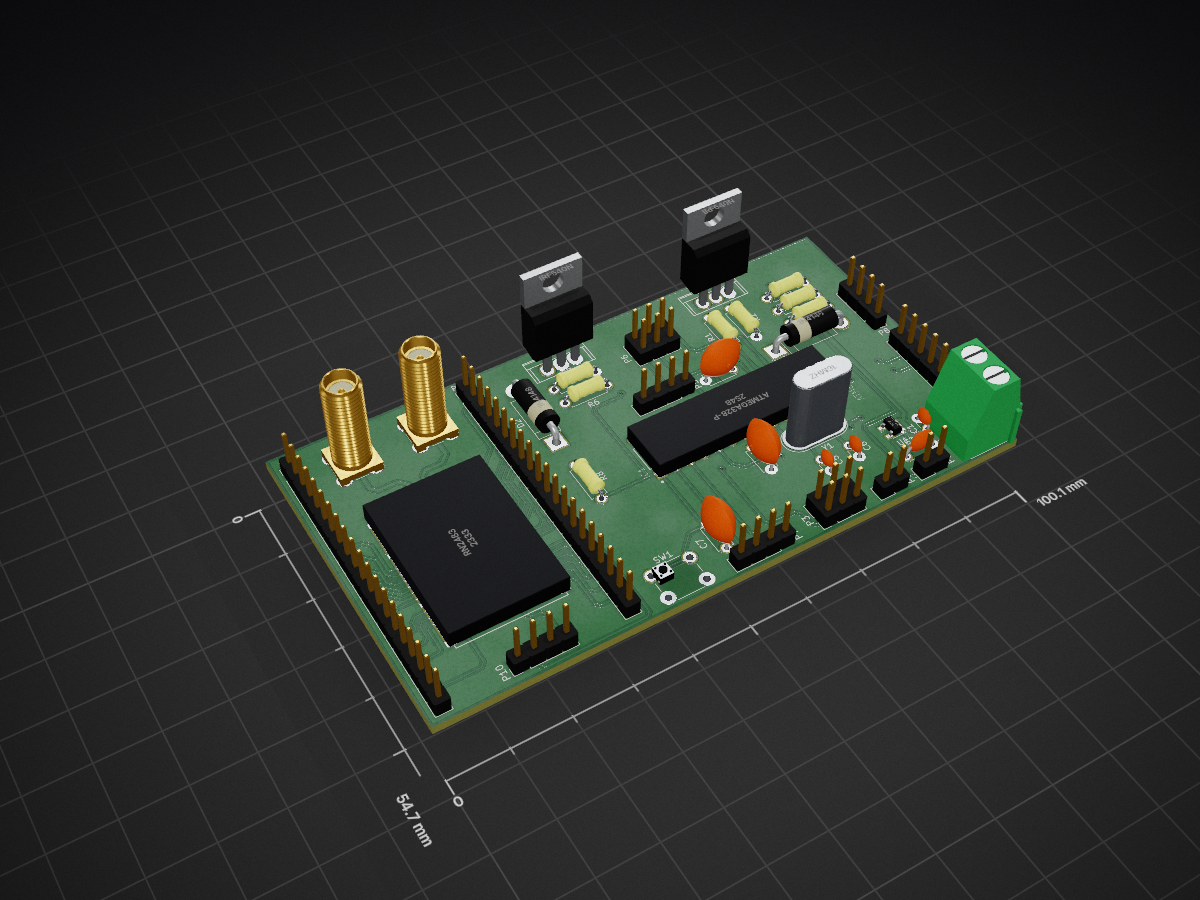
Deploying smart garbage bins for real time waste management system is one of the key applications of a smart city system.
BinLora is an open-source printed circuit board by manasdas17, from the manasdas17/LoRa-SmartGarbageCollection repository on GitHub. It is a 2-layer board of 100.1 × 54.7 mm with 38 parts on 63 nets, routed with 570 tracks and 30 vias.
It is built around the ATMEGA328-PU and IRF540N. Its parts include 12 connectors, 8 resistors, 7 capacitors, 3 ICs and 2 diodes. It belongs with the radio and wireless boards and the AVR (ATmega, ATtiny) boards of this library.


Manas Das (manasdas17@gmail.com)
Deploying smart garbage bins for real time waste management system is one of the key applications of a smart city system. Municipal authorities need an efficient way to clear the trash from all public places before it becomes a mess. And this needs to be achieved with the minimum overhead of cost and impact to the city dwellers. LoRaWAN is one of the earlier LPWAN technologies that envisages a city-wide network for keeping track of public infrastructure assets. Once fitted with a BLS(Bin Level Sensing) device on a trash can, LoRaWAN allows the city authorities to keep a tab on the bins via wireless connectivity. LoRaWAN does suffer from some limitations, such as extremely low data rates, higher collision and deteriorated network performance with increasing number of nodes and inability to perform over the air updates to the device.
Remove the items that do no apply to your project and keep the remaining ones.
To run the dashboard app, please go inside the folder from terminal and type nodejs app.js
Please give references to importance resources.
| Qty | Value | Footprint | References |
|---|---|---|---|
| 3 | 0 | Resistors_THT:R_Axial_DIN0207_L6.3mm_D2.5mm_P7.62mm_Horizontal | R3, R4, R5 |
| 3 | 100nF | Capacitors_THT:C_Disc_D4.7mm_W2.5mm_P5.00mm | C3, C4, C7 |
| 3 | 10K | Resistors_THT:R_Axial_DIN0207_L6.3mm_D2.5mm_P7.62mm_Horizontal | R2, R7, R8 |
| 2 | 1K | Resistors_THT:R_Axial_DIN0207_L6.3mm_D2.5mm_P7.62mm_Horizontal | R1, R6 |
| 2 | 1N4148 | Diodes_THT:D_5W_P12.70mm_Horizontal | D1, D2 |
| 2 | 22pF | Capacitors_THT:C_Disc_D3.0mm_W1.6mm_P2.50mm | C5, C6 |
| 2 | IRF540N | Power_Integrations:TO-220 | Q1, Q2 |
| 1 | 0.1uF | Capacitors_THT:C_Disc_D3.0mm_W1.6mm_P2.50mm | C1 |
| 1 | 16MHz | Crystals:Crystal_HC49-U_Vertical | Y1 |
| 1 | 1uF | Capacitors_THT:C_Disc_D4.3mm_W1.9mm_P5.00mm | C2 |
| 1 | 433 MHz | Connectors:SMA_THT_Jack_Straight | AE1 |
| 1 | 868 MHz | Connectors:SMA_THT_Jack_Straight | AE2 |
| 1 | ATMEGA328-P | bin:atmega328p | IC1 |
| 1 | Battery IN | Connectors_Terminal_Blocks:TerminalBlock_bornier-2_P5.08mm | J1 |
| 1 | Boost Input | Pin_Headers:Pin_Header_Straight_1x02_Pitch2.54mm | P1 |
| 1 | Boost Output | Pin_Headers:Pin_Header_Straight_1x02_Pitch2.54mm | P2 |
| 1 | DEBUG | Pin_Headers:Pin_Header_Straight_1x04_Pitch2.54mm | P7 |
| 1 | GPIO_ADC | Pin_Headers:Pin_Header_Straight_1x04_Pitch2.54mm | P5 |
| 1 | ICSP | Pin_Headers:Pin_Header_Straight_2x03_Pitch2.54mm | P6 |
| 1 | LORA_PORT | Pin_Headers:Pin_Header_Straight_1x04_Pitch2.54mm | P10 |
| 1 | PIN_1 | Pin_Headers:Pin_Header_Straight_1x20_Pitch2.54mm | P9 |
| 1 | PIN_2 | Pin_Headers:Pin_Header_Straight_1x20_Pitch2.54mm | P11 |
| 1 | Power | Pin_Headers:Pin_Header_Straight_2x03_Pitch2.54mm | P3 |
| 1 | RN2483 | bin:RN2483 | U2 |
| 1 | RTC | Pin_Headers:Pin_Header_Straight_1x06_Pitch2.54mm | P4 |
| 1 | SENSOR | Pin_Headers:Pin_Header_Straight_1x04_Pitch2.54mm | P8 |
| 1 | SW_PUSH | Buttons_Switches_THT:SW_PUSH_6mm | SW1 |
| 1 | TLV741P | TO_SOT_Packages_SMD:SOT-23-5 | U1 |
Sudo-Guts/SPWM
Proyecto de control y etapa de potencia de un inversor trifásico con modulación sinusoidal por ancho de pulso (SPWM).

ARTS-Laboratory/Biphasic-data-acquisition-system
Data acquisition system for the biphasic measurement of multifunctional material


profdc9/DRSSTC-PCB-Pack
A pack of PCBs for a dual resonant solid state tesla coil setup. Pretty much everything you need.


It measures 100.1 × 54.7 mm and has 2 copper layers, 1.6 mm thick.
38 parts, built around the ATMEGA328-PU and IRF540N. The full list of its parts is on this page, with links to each part's symbol and footprint where PCBKit's library has them.
From the manasdas17/LoRa-SmartGarbageCollection repository on GitHub, at the commit this page was made from: the board is Code/pcbDesign/binLora.kicad_pcb. PCBKit opens the board in the browser, with nothing to install.
Its repository states no licence, so its author keeps all rights: ask manasdas17 before reusing the design.