2 layers46.1 × 34.5 mm
C128 USB C PD Power Adapter
mamejay/C64-USB-C-PD-Power-Adapter
USB-C PD power adapter for the Commodore 64 (KiCad, JLCPCB-ready)
49 parts

 mamejay/C64-USB-C-PD-Power-Adapter
USB-C PD power adapter for the Commodore 64 (KiCad, JLCPCB-ready)
C64 USB C PD Power Adapter is an open-source printed circuit board by mamejay, from the mamejay/C64-USB-C-PD-Power-Adapter repository on GitHub. It is a 2-layer board of 46.1 × 30 mm with 51 parts on 45 nets, routed with 336 tracks and 22 vias.
It is built around the CH224A, M2.5 and AO3401A, with the SMF13A and SMF5.0A among its other parts. Its parts include 22 resistors, 14 capacitors, 5 ICs, 3 diodes and 2 connectors. It belongs with the power and retro computing and games boards of this library.


A compact replacement power supply for the Commodore 64. It plugs straight into the C64's 7-pin DIN power socket and runs from any USB-C Power Delivery charger that offers 15 V.
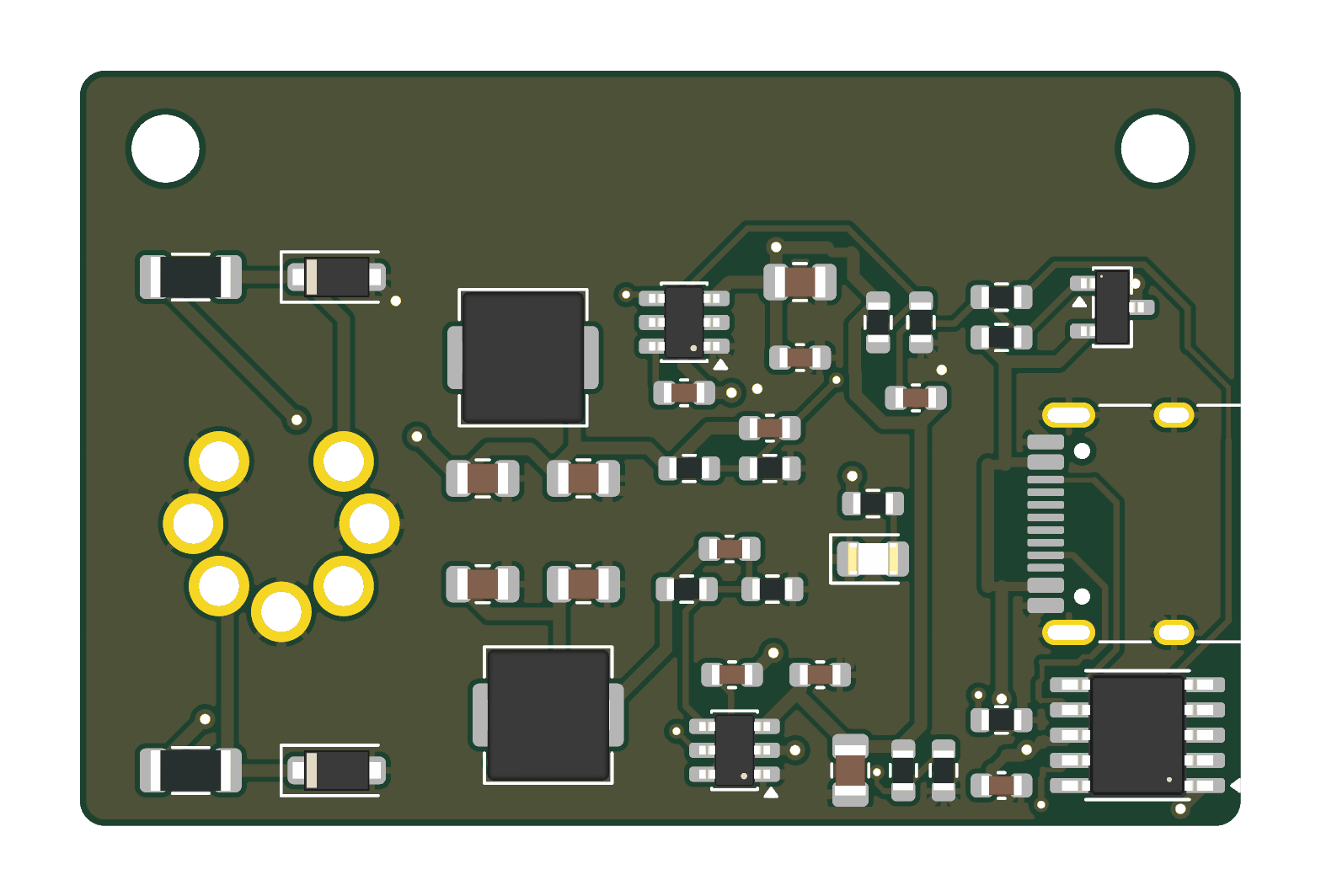
Status: v0.3 built and tested — working on a real C64. Measured with the C64 running: 5.07 V on pins 4/5, 12.3 V on pin 6 (12.3 V with no load as well).
v0.3 (cost-down):
| Output | DIN pin | Source |
|---|---|---|
| +5.07 V, up to 3 A | 4, 5 | TPS54302 buck (U2) |
| +12.3 V DC, ~1 A | 6 (the C64's "9 VAC" input) | TPS54302 buck (U3) |
| GND | 1, 2, 3, 7 |
The C64 runs its "9 VAC" input through its own bridge rectifier and a 7812 (breadbin) or 7809 (C64C).
Limitations: the supply is DC only, so the CIA time-of-day clock won't tick, and user-port devices that need real AC won't work. Same as other DC C64 supplies.
Hardware/KiCad/: KiCad 10 project (schematic, routed PCB, project libraries).Hardware/scripts/: the generators and routing pipeline:
gen_sch.py: schematic.build_v03.py: board build from the saved placement (place_v02.json + overrides_v03.json).add_holes.py: mounting holes.set_netclasses.py, then autoroute_v02.sh (Freerouting 2.5.0), then gnd_pours.py, then texts_upright.py.make_din_fp.py: DIN-7 footprint.make_fab.py: JLC outputs.Case (3D print)/: OpenSCAD case (base and lid), STLs and renders. Not yet test-printed; see its README.JLCPCB Output/: Gerbers zip, BOM, CPL and ORDER NOTES.txt.
Tested OK (first build, Nov 2026):
Still to test:
Measuring tip: pin 6 is DC, even though the C64 labels it "9 VAC". Measure it on the meter's DC range: on the AC range a meter shows a misleading figure, about 8 V here.
Hardware v0.4/ is v0.3 with an eFuse (TI TPS259470A) on each output in place of the F1/F2 links. It is designed and DRC-clean but not yet built.
See C128 Version/ for the Commodore 128 variant (v0.1, not yet built). It has:
CC BY-NC-SA 4.0: personal and non-commercial use only. Selling boards, kits, assembled units, cases or modified versions is not permitted. See NOTICE.md for the plain-English terms. Commercial use needs a separate written licence from the author.
This is an independent design. The commercial Sordan/RetroJoy adapter and Side Projects Lab's PD-64 (CC BY-NC-ND) were looked at for ideas only. No files or circuitry were copied from either.
| Qty | Value | Footprint | References |
|---|---|---|---|
| 5 | 100nF/50V | C64_PD_PSU:C_0603_1608Metric | C2, C4, C5, C10, C11 |
| 4 | 100k | C64_PD_PSU:R_0603_1608Metric | R2, R3, R11, R13 |
| 4 | 22uF/25V | C64_PD_PSU:C_0805_2012Metric | C6, C7, C12, C13 |
| 4 | 47k | C64_PD_PSU:R_0603_1608Metric | R5, R10, R14, R18 |
| 2 | 100pF | C64_PD_PSU:C_0603_1608Metric | C8, C14 |
| 2 | 10k | C64_PD_PSU:R_0603_1608Metric | R7, R19 |
| 2 | 10uF/25V | C64_PD_PSU:C_0805_2012Metric | C3, C9 |
| 2 | 10uH | C64_PD_PSU:L_Changjiang_FXL0530 | L1, L2 |
| 2 | 1k | C64_PD_PSU:R_0603_1608Metric | R8, R17 |
| 2 | 470k | C64_PD_PSU:R_0603_1608Metric | R4, R9 |
| 2 | 75k | C64_PD_PSU:R_0603_1608Metric | R6, R15 |
| 2 | M2.5 | C64_PD_PSU:MountingHole_2.7mm_M2.5 | H1, H2 |
| 2 | TPS259470ARPWR | C64_PD_PSU:TI_RPW0010A_VQFN-10-HR_2x2mm | U4, U5 |
| 2 | TPS54302DDCR | C64_PD_PSU:TSOT-23-6 | U2, U3 |
| 1 | 1uF/50V | C64_PD_PSU:C_0603_1608Metric | C1 |
| 1 | 2.2k | C64_PD_PSU:R_0603_1608Metric | R22 |
| 1 | 20k | C64_PD_PSU:R_0603_1608Metric | R16 |
| 1 | 4.7k | C64_PD_PSU:R_0603_1608Metric | R21 |
| 1 | 5.1k | C64_PD_PSU:R_0603_1608Metric | R12 |
| 1 | 51k | C64_PD_PSU:R_0603_1608Metric | R20 |
| 1 | 56k | C64_PD_PSU:R_0603_1608Metric | R1 |
| 1 | AO3401A | C64_PD_PSU:SOT-23 | Q1 |
| 1 | C64 POWER (DIN-7 male) | C64_PD_PSU:DIN-7_Male_PCB_C64 | J2 |
| 1 | CH224A | C64_PD_PSU:SSOP-10-1EP_3.9x4.9mm_P1mm_EP2.1x3.3mm | U1 |
| 1 | GREEN | C64_PD_PSU:LED_0805_2012Metric | D3 |
| 1 | SMF13A | C64_PD_PSU:D_SOD-123F | D2 |
| 1 | SMF5.0A | C64_PD_PSU:D_SOD-123F | D1 |
| 1 | USB-C (power in) | C64_PD_PSU:USB_C_Receptacle_HRO_TYPE-C-31-M-12 | J1 |
mamejay/C64-USB-C-PD-Power-Adapter
USB-C PD power adapter for the Commodore 64 (KiCad, JLCPCB-ready)

mamejay/C64-USB-C-PD-Power-Adapter
USB-C PD power adapter for the Commodore 64 (KiCad, JLCPCB-ready)

fabiansteiner/OpenValve
3D-printable pinch valve for irrigation and sensor-driven liquid control.


mschneider-git/zigbee-roller-shutter
Zigbee retrofit for a Heim & Haus solar roller shutter: ESP32-H2 sleepy end device firmware (ESP-IDF) and carrier PCB, for Home Assistant ZHA


shachi-lab/greaseweazle-v41-plus
Greaseweazle V4.1 based compatible board design for 3.5/5.25-inch FDDs

nikolaus018/garageDoor-pro
ESP32-C3 + GPS board that opens the garage door when you leave and arrive: firmware, KiCad PCB and perfboard build
It measures 46.1 × 30 mm and has 2 copper layers, 1.6 mm thick.
51 parts, built around the CH224A, M2.5, AO3401A and SMF13A. The full list of its parts is on this page, with links to each part's symbol and footprint where PCBKit's library has them.
From the mamejay/C64-USB-C-PD-Power-Adapter repository on GitHub, at the commit this page was made from: the board is Hardware v0.4/KiCad/C64 USB-C PD Power Adapter.kicad_pcb and its schematic C128 Version/KiCad/C128 USB-C PD Power Adapter.kicad_sch. PCBKit opens the board in the browser, with nothing to install.
Its repository states no licence, so its author keeps all rights: ask mamejay before reusing the design.