2 layers96.5 × 63.5 mm
 Malcollm/PDB4
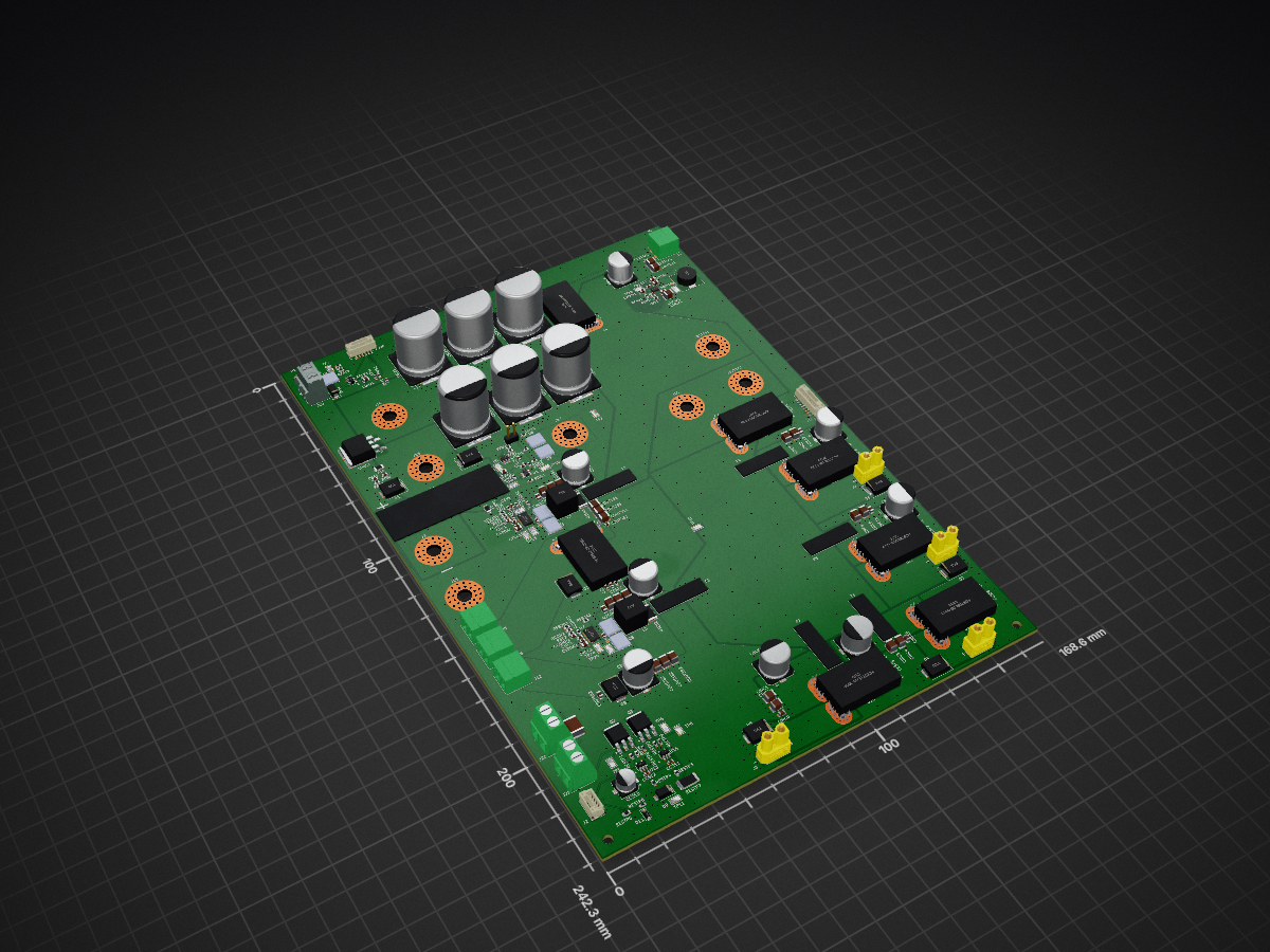
Power distribution board pcb
Main PDB is an open-source printed circuit board by Malcollm, from the Malcollm/PDB repository on GitHub. It is a 6-layer board of 168.6 × 242.3 mm with 241 parts on 118 nets, routed with 689 tracks and 1,025 vias.
It is built around the ACS758LCB-100B-PFF-T, LMR36015ARNXR and BSC070N10LS5ATMA1, with the BSC146N10LS5 among its other parts. Its parts include 17 connectors, 13 ICs, 10 diodes, 9 transistors and 9 fuses. It belongs with the robots and motor control boards of this library.


This repository contains the power distribution board design for the Wiscohumanoids humanoid robot. The board distributes the main battery power to the robot’s high-current actuator system and generates regulated lower-voltage rails for compute, servos, sensors, and control electronics.
The PDB is designed around a 48 V main power system with onboard regulation for the robot’s auxiliary electronics.
The power distribution board is responsible for taking the main battery input and safely distributing power throughout the robot. It includes high-current 48 V distribution, onboard buck converters, current sensing, precharge circuitry, and protection/disconnect circuitry.
The main goals of this board are:
Battery Input
    |
    |-- Precharge Circuit
    |
    |-- Main 48 V Power Rail
            |
            |-- Protection / Disconnect Circuitry
                    |
                    |-- Actuator / Servo Power Group
                    |       |
                    |       |-- 48 V Actuator Distribution
                    |       |
                    |       |-- 48 V to 6 V Buck Converter
                    |               |
                    |               |-- Hand Servos
                    |
                    |-- Compute / Control Power Group
                            |
                            |-- 48 V to 24 V Buck Converter
                            |       |
                            |       |-- Compute / Embedded Electronics
                            |
                            |-- 48 V to 3.3 V Buck Converter
                                    |
|-- Sensors / Current Sensors / Control Logic| Rail | Purpose |
|---|---|
| 48 V | Main battery rail and actuator power distribution |
| 24 V | Compute and embedded electronics |
| 6 V | Servo motors in the robot hands |
| 3.3 V | Sensors, current sensors, and control logic |
The main power path distributes 48 V battery power to the robot’s actuator system. Because this rail carries the highest current on the board, the layout uses large copper pours, short current paths, and high-current connectors.
This section of the board is designed to minimize voltage drop and reduce heating under actuator load.
The board includes a precharge circuit to limit inrush current when the battery is connected. This is important because the board contains large bulk capacitance on the main 48 V rail.
During startup, the precharge path slowly charges the bulk capacitors before the main power path is fully enabled. This reduces stress on connectors, switches, relays, and other power components.
The PDB includes protection and disconnect circuitry that separates the main power system into two groups: the actuator/servo power group and the compute/control power group.
The actuator/servo group contains the 48 V actuator distribution and the 6 V hand servo rail. This group can be disconnected from the rest of the system so high-power motion components can be shut down independently.
The compute/control group contains the 12 V and 3.3 V rails. This allows the robot’s control electronics, sensors, and compute hardware to remain separated from the high-power actuator section.
This separation is important because it allows actuator power to be disabled while keeping control electronics available for monitoring, communication, and safe shutdown behavior.
Protection features include:
Current sensors are included on important power paths so the robot can monitor how much current different parts of the system are drawing.
Current measurement is useful for:
The PDB generates the lower-voltage rails from the main 48 V battery input using buck converters.
The onboard regulated rails are:
Each buck converter section includes the switching regulator circuit, input capacitance, output capacitance, feedback network, and supporting passives.
The board uses separate ground naming to keep high-current power paths and sensitive measurement/control paths organized.
Typical ground nets include:
| Net | Purpose |
|---|---|
| PGND | High-current power ground and switching converter return |
| AGND | Analog/sensor ground for feedback and current measurement circuits |
These grounds are not meant to be completely isolated systems. Instead, the separate names help control where large return currents flow and help keep sensor and feedback references cleaner.
This project is currently in development.
| Qty | Value | Footprint | References |
|---|---|---|---|
| 16 | Keystone 5015 | TestPoint:TestPoint_Keystone_5015_Micro_Mini | TP1, TP2, TP3, TP4, TP5, TP6, TP7, TP8, TP9, TP10, TP11, TP12, TP13, TP14, TP15, TP16 |
| 14 | 4.7u | Capacitor_SMD:C_1210_3225Metric | CIN2B1, CIN2B2, CIN3B1, CIN3B2, CIN4B1, CIN4B2, CINC1, CINC2, CINC3, CINC4, CINC5, CINC6, CINC7, CINC8 |
| 13 | 100n | Capacitor_SMD:C_0603_1608Metric | CBOOT1, CBOOT3, CCS1, CCS2, CCS3, CCS4, CCS5, CCS6, CCS7, CCS8, CCS9, CVDDA1, CVDDA2 |
| 11 | NetTie_2 | Footprints:NetTie_AGND_PGND_VIA | NT1, NT2, NT3, NT4, NT5, NT6, NT7, NT8, NT9, NT10, NT11 |
| 9 | 100k | Resistor_SMD:R_0603_1608Metric | RENT1, RESTP8, RESTP9, RPD1, RPD2, RPDP1, RPDQ1, RUV1, RUV2 |
| 8 | 100nF | Capacitor_SMD:C_0805_2012Metric | CIN5A1, CIN5B1, CIN5B2, CINC9, CINC10, CINC11, CINC12, COUT4B2 |
| 8 | TVS | Diode_SMD:D_SMC | D1, D2, D3, D4, D5, D6, D7, D8 |
| 7 | 10n | Capacitor_SMD:C_0603_1608Metric | CCSF1, CCSF2, CCSF4, CCSF5, CCSF6, CCSF7, CCSF8 |
| 7 | 1k | Resistor_SMD:R_0603_1608Metric | RCSF1, RCSF2, RCSF4, RCSF5, RCSF6, RCSF7, RCSF8 |
| 7 | ACS758LCB-100B-PFF-T | Footprints:XDCR_ACS758LCB-100U-PFF-T | U4, U5, U8, U9, U10, U11, U12 |
| 6 | 22uF | Capacitor_SMD:C_1210_3225Metric | COUT1B1, COUT1B2, COUT2B1, COUT2B2, COUT3B1, COUT3B2 |
| 6 | 470u | Capacitor_SMD:CP_Elec_18x22 | CBLK3, CBLK4, CBLK5, CBLK6, CBLK7, CBLK8 |
| 6 | ~ | LITTLEFUSE_178.6165.0002:LITTELFUSE_178.6165.0002 | F2, F3, F4, F5, F6, F7 |
| 5 | 100nF | Capacitor_SMD:C_0603_1608Metric | CBOOT2, CBS1, COUT3A1, COUT4B1, CPS1 |
| 5 | BSC070N10LS5ATMA1 | Package_SON:VSONP-8-1EP_5x6_P1.27mm | Q1, Q5, Q6, Q8, Q9 |
| 4 | 100uF | Capacitor_SMD:CP_Elec_10x10 | CBLKA1, CBLKA2, CBULK2, CIN1B2 |
| 4 | 47uF | Capacitor_SMD:CP_Elec_10x10 | CBLKA3, CBLKA4, CIN1A1, CIN1B1 |
| 4 | Conn_01x02 | Footprints:AMASS_XT30UPB-F_1x02_P5.0mm_Vertical | J7, J8, J9, J10 |
| 4 | MountingHole_3.2mm_M3 | MountingHole:MountingHole_3.2mm_M3 | H1, H2, H3, H4 |
| 3 | 100R | Resistor_SMD:R_0603_1608Metric | RESTP1, RESTP2, RG1 |
| 3 | 10k | Resistor_SMD:R_0603_1608Metric | RFB2B1, RFB2B2, RPU3 |
| 3 | 22pF | Capacitor_SMD:C_0603_1608Metric | CFF1, CHF1, CHF2 |
| 3 | MCP1402T-E/OT | Footprints:SOT-23-5_MC_MCH | U13, U14, U15 |
| 3 | SW probe pad | TestPoint:TestPoint_Pad_D1.0mm | TP17, TP18, TP19 |
| 2 | 0.004R | Resistor_SMD:R_2512_6332Metric | RSEN1, RSEN2 |
| 2 | 0.5A | Fuse:Fuse_1206_3216Metric | F8, F10 |
| 2 | 100k | Capacitor_SMD:C_0603_1608Metric | RBS1, RPS1 |
| 2 | 100nF 50V | Capacitor_SMD:C_0603_1608Metric | CCS11, CCS12 |
| 2 | 1uF | Capacitor_SMD:C_0805_2012Metric | CDRV1, CVCCA1 |
| 2 | 2.2R | Resistor_SMD:R_0603_1608Metric | RDM1, RDM2 |
| 2 | 2.2k | Resistor_SMD:R_0603_1608Metric | RESTP3, RESTP4 |
| 2 | 2.2u | Capacitor_SMD:C_0805_2012Metric | CVCC1, CVCC2 |
| 2 | 220nF | Capacitor_SMD:C_0805_2012Metric | CHF4A1, CIN3A1 |
| 2 | 3.9k | Resistor_SMD:R_0603_1608Metric | RBS2, RPS2 |
| 2 | 4.7R | Resistor_SMD:R_0603_1608Metric | RFB1, RFB2 |
| 2 | 41.2k | Resistor_SMD:R_0603_1608Metric | RCON1, RCON2 |
| 2 | 47k | Resistor_SMD:R_0603_1608Metric | RSF1, RSF2 |
| 2 | 47uF | Capacitor_SMD:C_1210_3225Metric | COUT1A1, COUT2A1 |
| 2 | BSC146N10LS5 | Package_SON:VSONP-8-1EP_5x6_P1.27mm | Q4, Q7 |
| 2 | LM5148RGYR | Footprints:QFN50P550X350X100-25N | U2, U7 |
| 2 | NMOS IRFR220N | Package_TO_SOT_SMD:TO-252-3_TabPin2 | Q2, Q3 |
| 1 | 1.65M | Capacitor_SMD:C_0805_2012Metric | RFBC1 |
| 1 | 100 | Footprints:TO-263-2_Resistor | RPRE1 |
| 1 | 100k | Resistor_SMD:R_0805_2012Metric | RESTP5 |
| 1 | 100uF 35V | Capacitor_SMD:CP_Elec_6.3x5.4 | CCS10 |
| 1 | 10uH | Inductor_SMD:L_Coilcraft_XAL8080-XXX | L2 |
| 1 | 12.1k | Resistor_SMD:R_0603_1608Metric | RCOMP2 |
| 1 | 12V Zener 1W | Diode_SMD:D_SMA | D9 |
| 1 | 18uH | Footprints:L_Sumida_CDRH104R | L1 |
| 1 | 19.1k | Resistor_SMD:R_0603_1608Metric | RCOMP1 |
| 1 | 1M | Resistor_SMD:R_0603_1608Metric | RDIV1 |
| 1 | 1nF | Capacitor_SMD:C_0603_1608Metric | CEN1 |
| 1 | 2.7nF | Capacitor_SMD:C_0603_1608Metric | CCOMP2 |
| 1 | 24V Out -> Jetson | Connector_Phoenix_MC:PhoenixContact_MC_1,5_2-G-3.81_1x02_P3.81mm_Horizontal | J5 |
| 1 | 24V Out -> USB-C-PD controller | Connector_Phoenix_MC:PhoenixContact_MC_1,5_2-G-3.81_1x02_P3.81mm_Horizontal | J6 |
| 1 | 24k | Resistor_SMD:R_0603_1608Metric | RDIV2 |
| 1 | 291k | Resistor_SMD:R_0603_1608Metric | RFB1A2 |
| 1 | 2nF | Capacitor_SMD:C_0603_1608Metric | CCOMP1 |
| 1 | 3.3V Out | Connector_Phoenix_MC:PhoenixContact_MC_1,5_2-G-3.81_1x02_P3.81mm_Horizontal | J4 |
| 1 | 3.3V Zener | Diode_SMD:D_SOD-123 | D11 |
| 1 | 4.7K 1W | Resistor_SMD:R_2512_6332Metric | RESTP7 |
| 1 | 4.7uF | Capacitor_SMD:C_1210_3225Metric | CIN2A1 |
| 1 | 4.7uH | Inductor_SMD:L_Coilcraft_XAL8080-XXX | L3 |
| 1 | 43.2k | Resistor_SMD:R_0603_1608Metric | RENB1 |
| 1 | 64.9k | Resistor_SMD:R_0603_1608Metric | RFB1A1 |
| 1 | 6V Out | Connector_Phoenix_MC:PhoenixContact_MC_1,5_2-G-3.81_1x02_P3.81mm_Horizontal | J12 |
| 1 | 7.5k | Resistor_SMD:R_0603_1608Metric | RESTP6 |
| 1 | BC_Disconnect | Connector_PinHeader_2.54mm:PinHeader_1x02_P2.54mm_Vertical | J18 |
| 1 | Conn_01x04 | Connector_JST:JST_GH_BM04B-GHS-TBT_1x04-1MP_P1.25mm_Vertical | J2 |
| 1 | Conn_01x08 | Connector_JST:JST_GH_BM08B-GHS-TBT_1x08-1MP_P1.25mm_Vertical | J11 |
| 1 | Conn_Batt_GND | Footprints:MountingHole_5.3mm_M5_Pad_Via_HP | J15 |
| 1 | Conn_Batt_PWR | Footprints:MountingHole_5.3mm_M5_Pad_Via_HP | J3 |
| 1 | Dump_Resistor_In | Footprints:MountingHole_5.3mm_M5_Pad_Via_HP | J16 |
| 1 | Dump_Resistor_Out | Footprints:MountingHole_5.3mm_M5_Pad_Via_HP | J17 |
| 1 | ESTOP Button (Normally Closed) | TerminalBlock:TerminalBlock_MaiXu_MX126-5.0-02P_1x02_P5.00mm | J21 |
| 1 | ESTOP Contactor Coil Control | TerminalBlock:TerminalBlock_MaiXu_MX126-5.0-02P_1x02_P5.00mm | J20 |
| 1 | ESTOP_IN | Footprints:MountingHole_5.3mm_M5_Pad_Via_HP | JESTOP1 |
| 1 | ESTOP_OUT | Footprints:MountingHole_5.3mm_M5_Pad_Via_HP | JESTOP2 |
| 1 | Fuse | Footprints:FUSE_BF1_M5_100A | F1 |
| 1 | LMR36015ARNXR | Footprints:RNX0012B | U3 |
The 232 most common of 241 parts.
It measures 168.6 × 242.3 mm and has 6 copper layers, 1.6 mm thick.
241 parts, built around the ACS758LCB-100B-PFF-T, LMR36015ARNXR, BSC070N10LS5ATMA1 and BSC146N10LS5. The full list of its parts is on this page, with links to each part's symbol and footprint where PCBKit's library has them.
From the Malcollm/PDB repository on GitHub, at the commit this page was made from: the board is Main_PDB.kicad_pcb and its schematic LM5143_Buck.kicad_sch. PCBKit opens the board in the browser, with nothing to install.
Its repository states no licence, so its author keeps all rights: ask Malcollm before reusing the design.


offgridevices/offgrid-hardware
Open hardware from OffGrid Devices. One folder per board. CERN-OHL-S.

nikolajevs/ai
Открыть PCBV1.kicadpro в KiCad 10. После обновления репозитория перечитать открытый проект с диска перед сохранением.

nikolajevs/PCB_EU
Сохраняются функции PCBV1: два LED-канала с общей яркостью, два независимых PWM/тахоканала вентиляторов, PTC, помпа, SHT4x, поплавок, RTC с CR2032, microSD, Wi-Fi и существующие функции интерфейса/расписаний.


FulongLi/AIPE-PCB-Agent
AIPE-PCB-Agent is the PCB design automation of the AIPE power-electronics ecosystem. Python generators turn a requirement file set (specification, insulation table, components, interfaces, floorplan and routing inputs)…