4 layers160 × 100 mm

 Mage-Control-Systems-Ltd/CANBOB8
A breakout board that enables USB or SPI to CAN communication using the MCP2515.
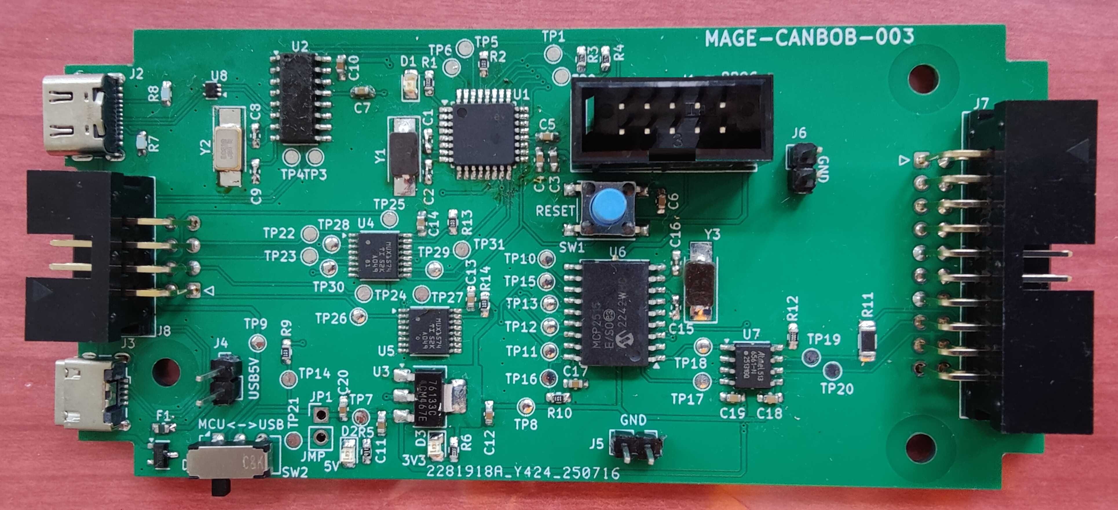
CANBOB (MAGE CANBOB-003) is an open-source printed circuit board by Mage-Control-Systems-Ltd, from the Mage-Control-Systems-Ltd/CANBOB repository on GitHub, published under the CC-BY-4.0 licence. It is a 2-layer board of 109.5 × 51 mm with 98 parts on 92 nets, routed with 785 tracks and 99 vias.
It is built around the ATA6561-GAQW-N, CH340C and TMUX1574PW, with the TLV76133DCY, TPD2E2U06DRLR-TP and 06035A130GAT2A among its other parts. Its parts include 20 capacitors, 14 resistors, 8 ICs, 8 connectors and 4 diodes. It belongs with the interfaces and adapters and microcontroller boards boards and the AVR (ATmega, ATtiny) boards of this library.



The CAN Break Out Board (or CANBOB) is a module board that enables USB or SPI to CAN communication using the MCP2515. The jobset generated files (i.e. Gerbers and BOM) are in the Releases section of the repository.
For programming the on-board ATmega please see the Programming ATmega.md file and for testing it with a Raspberry Pi see the Raspi CAN Setup.md.
CANBOB provides a single switch to switch between MCU Mode or USB Mode (See Figure 1 in the Images section below), indicated by the silkscreen near the slide switch. Use CANBOB in MCU Mode with an external microcontroller, or in USB Mode with a USB connection to a host. See instructions below for more information.
To use CANBOB in USB Mode make sure to slide the switch to the correct position and plug in your micro USB or USB-C cable to CANBOB and the host. See the Output Header section below for where to connect your outputs.
To use CANBOB with external microcontroller, slide the switch to the MCU Mode position. Connect the appropriate pins to the input header with the pinout below,
| Pin Number | Function | Description |
|---|---|---|
| 1 | CLK | SPI Clock Input |
| 2 | MOSI | SPI Main Out Sub In |
| 3 | MISO | SPI Main In Sub Out |
| 4 | CS | SPI Chip Select |
| 5 | INT | SPI Interrupt |
| 6 | 5V | 5V Supply |
| 7 | GND | Device Ground |
| 8 | GND | Device Ground |
Facing the connector, the top row has all the odd numbered pins, with the top right pin being pin 1, and the bottom row has all the even numbered pins. See Figure 2 in the Images section below.
The output header contains all the necessary CAN outputs like CAN H/L and CAN termination points. It is also used to breakout the remaining pins of the MCP2515 such as the Receive Buffers (RXxBUF) and the Transmit Buffers' RTS (TXxRTS) signals. The ATmega also has some pins broken out there such as 6 GPIOs or ADCs with 2 of them able to be used for I2C communication, and the UART RX/TX lines. Please see the pinout below,
| Pin Number | Function | Description |
|---|---|---|
| 1 | ADC3/GPIO3 | ATmega ADC/GPIO |
| 2 | ADC2/GPIO2 | ATmega ADC/GPIO |
| 3 | ADC1/GPIO1 | ATmega ADC/GPIO |
| 4 | ADC0/GPIO0 | ATmega ADC/GPIO |
| 5 | ADC5/GPIO5/SCL | ATmega ADC/GPIO |
| 6 | ADC4/GPIO4/SDA | ATmega ADC/GPIO |
| 7 | RX1BUF | MCP2515 Receive Buffer |
| 8 | RX0BUF | MCP2515 Receive Buffer |
| 9 | TX0RTS | MCP2515 Transmit Buffer RTS |
| 10 | TX1RTS | MCP2515 Transmit Buffer RTS |
| 11 | TX2RTS | MCP2515 Transmit Buffer RTS |
| 12 | CLKOUT | MCP2515 Clock Output |
| 13 | TX | ATmega TX |
| 14 | RX | ATmega RX |
| 15 | CANH | CAN High |
| 16 | CANL | CAN Low |
| 17 | CAN-JMP | CAN Jumper for termination |
| 18 | CAN-JMP | CAN Jumper for termination |
| 19 | GND | Device Ground |
| 20 | GND | Device Ground |
Facing the connector, the top row has all the odd numbered pins, with the top right pin being pin 1, and the bottom row has all the even numbered pins. See Figure 3 in the Images section below.
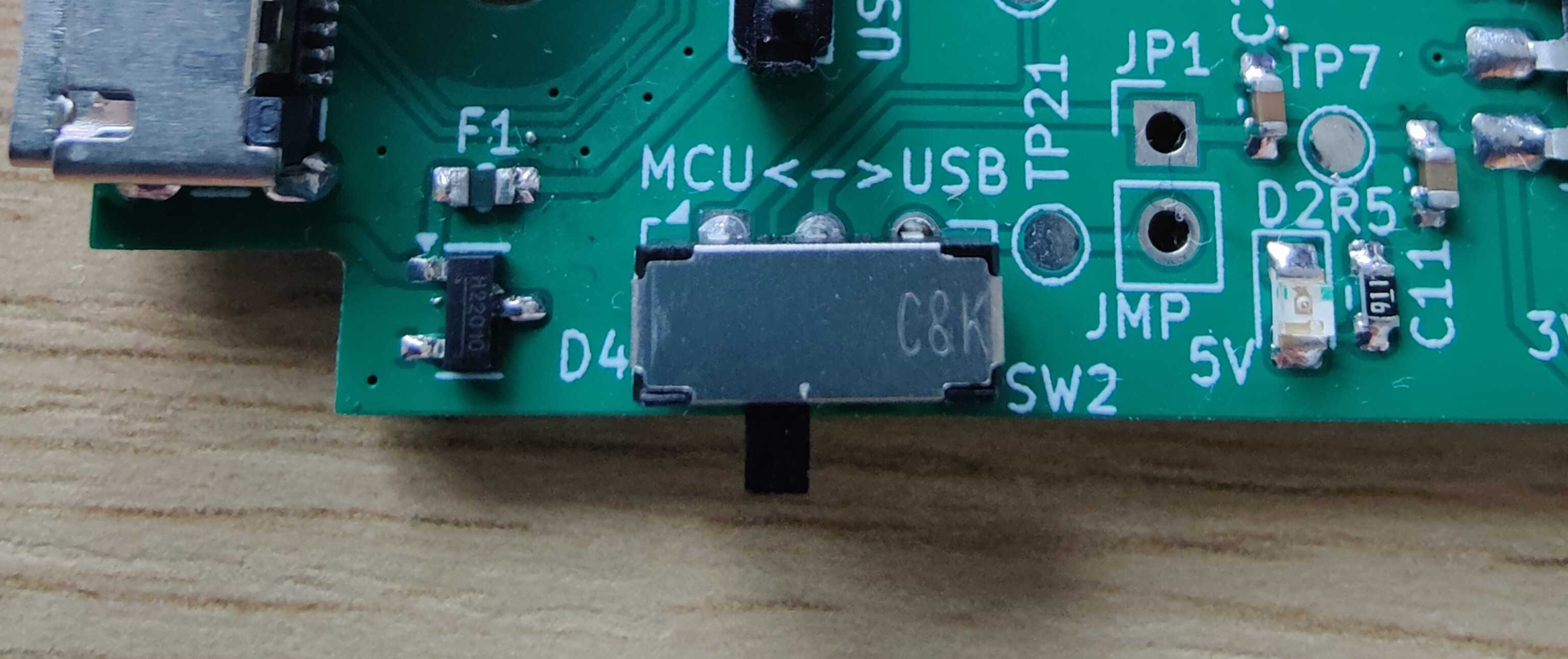 Figure 1. Showing slide switch
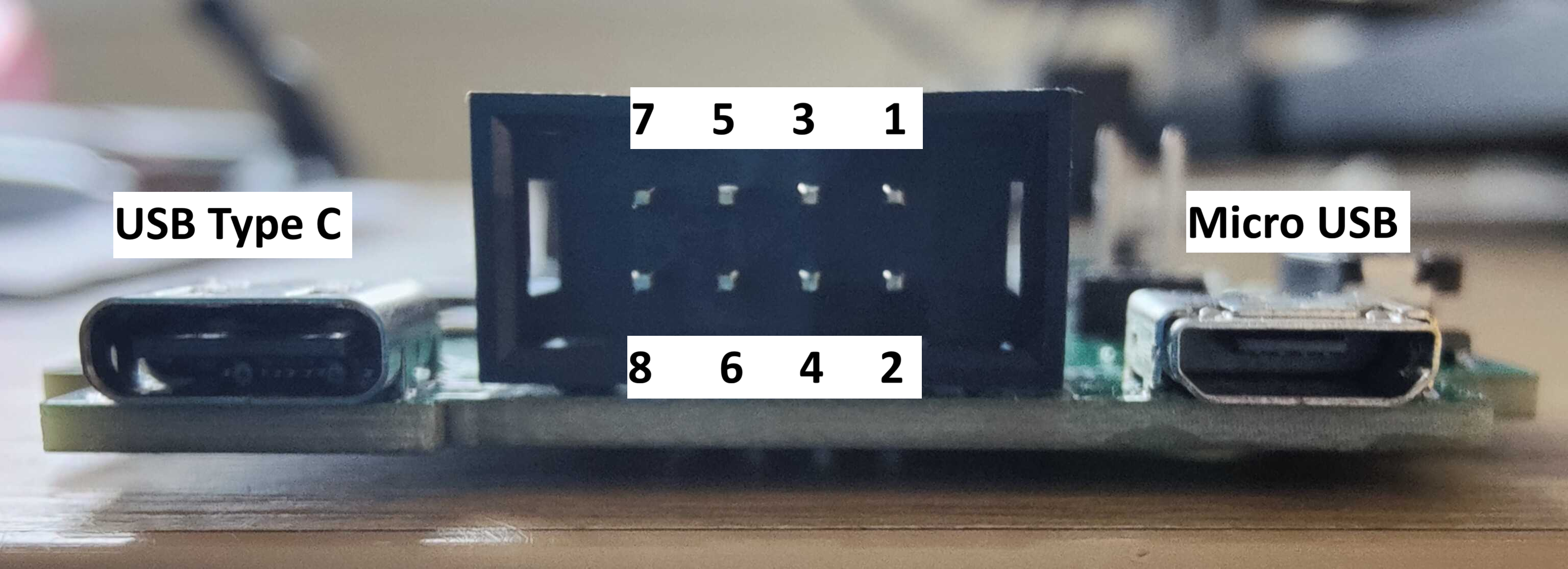 Figure 2. Showing input connectors and pinout
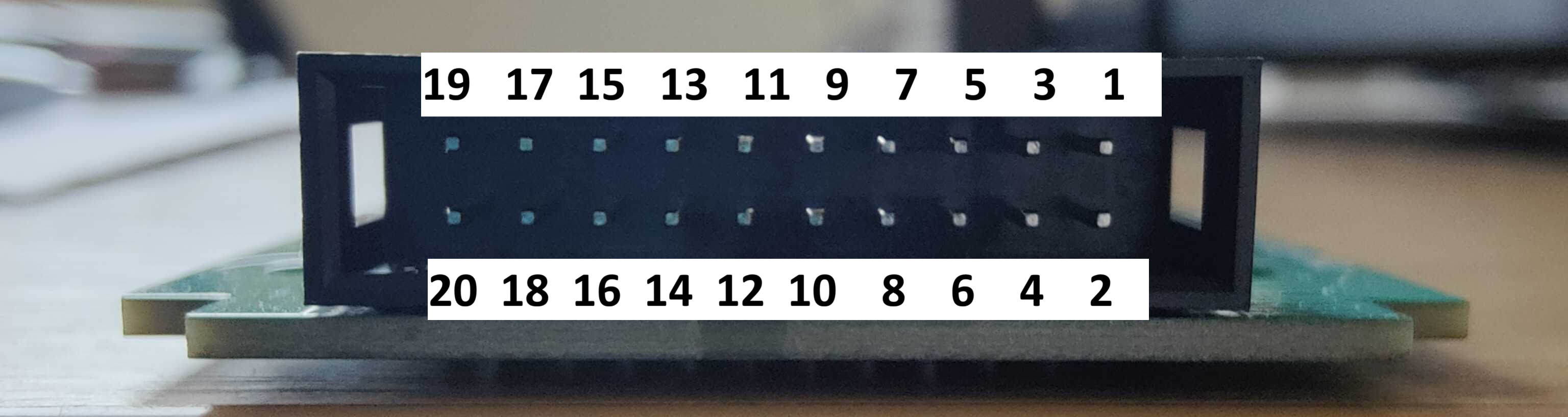 Figure 3. Showing output connector pinout
Hardware is located in hardware/PCB/ and is licensed under the CERN-OHL-P v2 License provided in LICENSE-CERN-OHL-P. User guide for the license is provided in cern_ohl_p_v2_howto.pdf.
Firmware located in firmware/arduino-canbus-monitor/ is licensed under the MIT License provided in LICENSE-MIT and more details regarding attribution are in firmware/README.md.
Documentation is licensed under Creative Commons Attribution 4.0 International and is provided in LICENSE-CC-BY.


Unless otherwise noted, all files in each directory are covered by the license listed above and are provided with absolutely NO WARRANTY.
Copyright (c) 2025 Mage Control Systems Ltd
| Qty | Value | Footprint | References |
|---|---|---|---|
| 31 | TestPoint_Small | TestPoint:TestPoint_Pad_D1.5mm | TP1, TP2, TP10, TP11, TP12, TP13, TP14, TP15, TP16, TP17, TP18, TP19, TP20, TP21, TP22, TP23 +15 |
| 6 | 13p | Capacitor_SMD:C_0603_1608Metric_Pad1.08x0.95mm_HandSolder | C1, C2, C8, C9, C15, C16 |
| 6 | 1u | Capacitor_SMD:C_0603_1608Metric_Pad1.08x0.95mm_HandSolder | C4, C10, C11, C13, C14, C17 |
| 5 | 100n | Capacitor_SMD:C_0603_1608Metric_Pad1.08x0.95mm_HandSolder | C5, C6, C7, C18, C19 |
| 5 | 10k | Resistor_SMD:R_0603_1608Metric_Pad0.98x0.95mm_HandSolder | R2, R9, R10, R13, R14 |
| 3 | Conn_01x02_Pin | Connector_PinHeader_2.54mm:PinHeader_1x02_P2.54mm_Vertical | J4, J5, J6 |
| 3 | MountingHole | MountingHole:MountingHole_3.2mm_M3 | H1, H2, H3 |
| 3 | Red | LED_SMD:LED_0805_2012Metric_Pad1.15x1.40mm_HandSolder | D1, D2, D3 |
| 2 | 16 MHz | Crystal:Crystal_SMD_5032-2Pin_5.0x3.2mm_HandSoldering | Y1, Y3 |
| 2 | 2u2 | Capacitor_SMD:C_0603_1608Metric_Pad1.08x0.95mm_HandSolder | C12, C20 |
| 2 | 330R | Resistor_SMD:R_0603_1608Metric_Pad0.98x0.95mm_HandSolder | R1, R6 |
| 2 | 4k7 | Resistor_SMD:R_0603_1608Metric_Pad0.98x0.95mm_HandSolder | R3, R4 |
| 2 | 5k1 | Resistor_SMD:R_0603_1608Metric_Pad0.98x0.95mm_HandSolder | R7, R8 |
| 2 | TMUX1574PW | Package_SO:TSSOP-16_4.4x5mm_P0.65mm | U4, U5 |
| 1 | 100R | Resistor_SMD:R_0603_1608Metric_Pad0.98x0.95mm_HandSolder | R12 |
| 1 | 10u | Capacitor_SMD:C_0603_1608Metric_Pad1.08x0.95mm_HandSolder | C3 |
| 1 | 12 MHz | Crystal:Crystal_SMD_5032-2Pin_5.0x3.2mm_HandSoldering | Y2 |
| 1 | 120R | Resistor_SMD:R_1206_3216Metric_Pad1.30x1.75mm_HandSolder | R11 |
| 1 | 910R | Resistor_SMD:R_0603_1608Metric_Pad0.98x0.95mm_HandSolder | R5 |
| 1 | ATA6561-GA | Package_SO:SOIC-8_3.9x4.9mm_P1.27mm | U7 |
| 1 | ATMEGA328PB_AUR | Package_QFP:TQFP-32_7x7mm_P0.8mm | U1 |
| 1 | CDSOT23-T05LC-Q | Package_TO_SOT_SMD:SOT-23-3 | D4 |
| 1 | CH340x | Package_SO:SOIC-16_3.9x9.9mm_P1.27mm | U2 |
| 1 | Conn_01x08_Pin | Connector_IDC:IDC-Header_2x04_P2.54mm_Horizontal | J8 |
| 1 | Conn_01x20_Pin | Connector_IDC:IDC-Header_2x10_P2.54mm_Horizontal | J7 |
| 1 | Conn_02x05_Odd_Even | Connector_IDC:IDC-Header_2x05_P2.54mm_Vertical | J1 |
| 1 | Fuse | Fuse:Fuse_0603_1608Metric_Pad1.05x0.95mm_HandSolder | F1 |
| 1 | Jumper_2_Small_Open | Connector_PinHeader_2.54mm:PinHeader_1x02_P2.54mm_Vertical | JP1 |
| 1 | LOGO | mage_ss | G*** |
| 1 | MCP2515T-E/SO | Package_SO:SOIC-18W_7.5x11.6mm_P1.27mm | U6 |
| 1 | NetTie_2 | NetTie:NetTie-2_SMD_Pad0.5mm | NT1 |
| 1 | SW_Push | Button_Switch_SMD:SW_SPST_PTS645Sx43SMTR92 | SW1 |
| 1 | SW_Slide_DPDT | Button_Switch_THT:SW_CK_JS202011AQN_DPDT_Angled | SW2 |
| 1 | TLV76133DCY | Package_TO_SOT_SMD:SOT-223-3_TabPin2 | U3 |
| 1 | TPD2E2U06DRL | Package_TO_SOT_SMD:SOT-553 | U8 |
| 1 | USB_B_Micro | Connector_USB:USB_Micro-B_Wuerth_629105150521 | J3 |
| 1 | USB_C_Receptacle_USB2.0_14P | Connector_USB:USB_C_Receptacle_JAE_DX07S016JA1R1500 | J2 |
The 97 most common of 98 parts.
It measures 109.5 × 51 mm and has 2 copper layers, 1.6 mm thick.
98 parts, built around the ATA6561-GAQW-N, CH340C, TMUX1574PW and TLV76133DCY. The full list of its parts is on this page, with links to each part's symbol and footprint where PCBKit's library has them.
From the Mage-Control-Systems-Ltd/CANBOB repository on GitHub, at the commit this page was made from: the board is hardware/PCB/CANBOB (MAGE-CANBOB-003).kicad_pcb and its schematic hardware/PCB/CANBOB (MAGE-CANBOB-003).kicad_sch. PCBKit opens the board in the browser, with nothing to install.
Its repository publishes it under the CC-BY-4.0 licence: you may reuse it on that licence's terms (keep the author's notice, and for a copyleft licence share your changes alike).


AndreiVladescu/ESP32-Bit-Pirate-Hardware
Carrier breaker-board for the ESP32-S3 Devkit. Works great with the ESP32-Bit-Pirate firmware.

Manawyrm/QSPIBuddy
SPI NOR Flash mux - Raspberry Pi for embedded firmware development - Mux between DUT and Flasher

fgihl/usb-c-passthrough
A USB 2.0 (480 Mbit/s) passthrough board that can electrically "unplug" a USB connection under software control — used for Hardware-in-the-Loop (HIL) testing.

WiiMake/picones
In the last 40 years, technology has advanced to the point were what used to be done in hardware can now be done in software. This project uses an rp2350 to emulate a ROM chip on an NES Cartridge.

maceintu/Ampli-D
Amplificateur audio stéréo classe D open hardware : entrées filaires et Bluetooth, DAC audiophile, pilotage par microcontrôleur STM32. Le dépôt contient l'ensemble de la conception — schémas, PCB et firmware.