2 layers45 × 29 mm

 maehw/DiyIrTower12
Do-it-yourself infrared serial communication tower (compatible with LEGO IR serial tower)
DiyIrTower is an open-source printed circuit board by maehw, from the maehw/DiyIrTower repository on GitHub, published under the GPL-3.0 licence. It is a 2-layer board of 32 × 48 mm with 17 parts on 13 nets, routed with 53 tracks and 0 vias.
It is built around the ATTINY13-20PU and TSAL6200. Its parts include 3 resistors, 3 diodes, 2 ICs and 2 connectors. It belongs with the interfaces and adapters boards and the AVR (ATmega, ATtiny) boards of this library.


Can be used as a replacement of the original LEGO IR serial tower with programs and platforms such as
firmdl3 command line download toolto load user programs and firmware on the yellow LEGO Mindstorms RCX programmable brick.
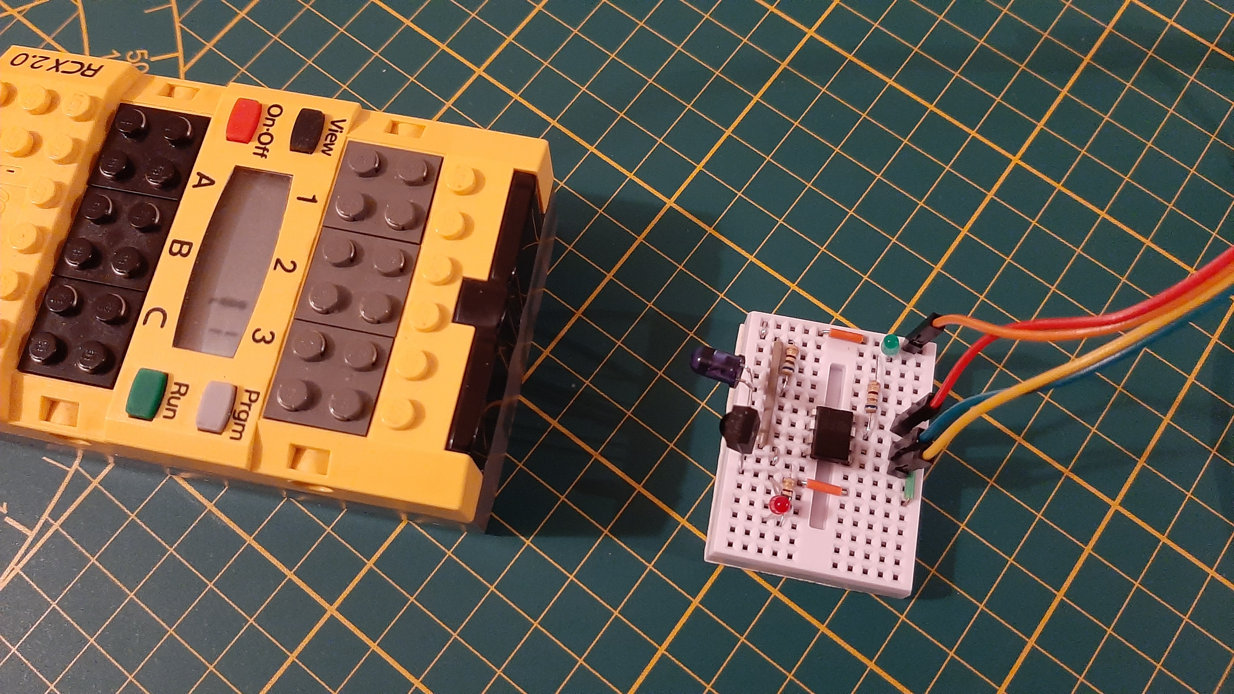
⚠️ Warning: Exposure to infrared light can cause harm to humans. Prolonged or intense exposure may lead to damage to the eyes or skin. Always use proper safety equipment when working with infrared light sources. Make sure to limit the current through the infrared TX LED!
At the heart of the DIY solution, there's an 8-pin ATtiny13A microcontroller.
Pin Assignment Table for the ATtiny13A:
| IC Pin | Pin | Purpose | Direction | Side of IC | ISP Usage |
|---|---|---|---|---|---|
| 1 | PB5 | Reset | Unused | Left | Reset |
| 2 | PB3 | IR_LED_TX_PIN | Output | Left | |
| 3 | PB4 | PHOTO_RX_PIN | Input | Left | |
| 4 | GND | Ground | - | Left | GND |
| 5 | PB0 | UART_RX_PIN | Output | Right | MOSI |
| 6 | PB1 | UART_TX_PIN | Input | Right | MISO |
| 7 | PB2 | IR_ACTIVITY_LED_PIN | Output | Right | SCK |
| 8 | VCC | Supply Voltage (VCC) | - | Right | VCC |
The column "ISP Usage" shows what pins need to be connected for programming ("flashing") by a 6-pin AVR In-System Programmer (ISP).
If you've built a working DiyIrTower yourself with these or different parts, please let me know! The first design has used the TSOP4338. As it's not available everywhere, it has also been tested to work with the TSOP4838.
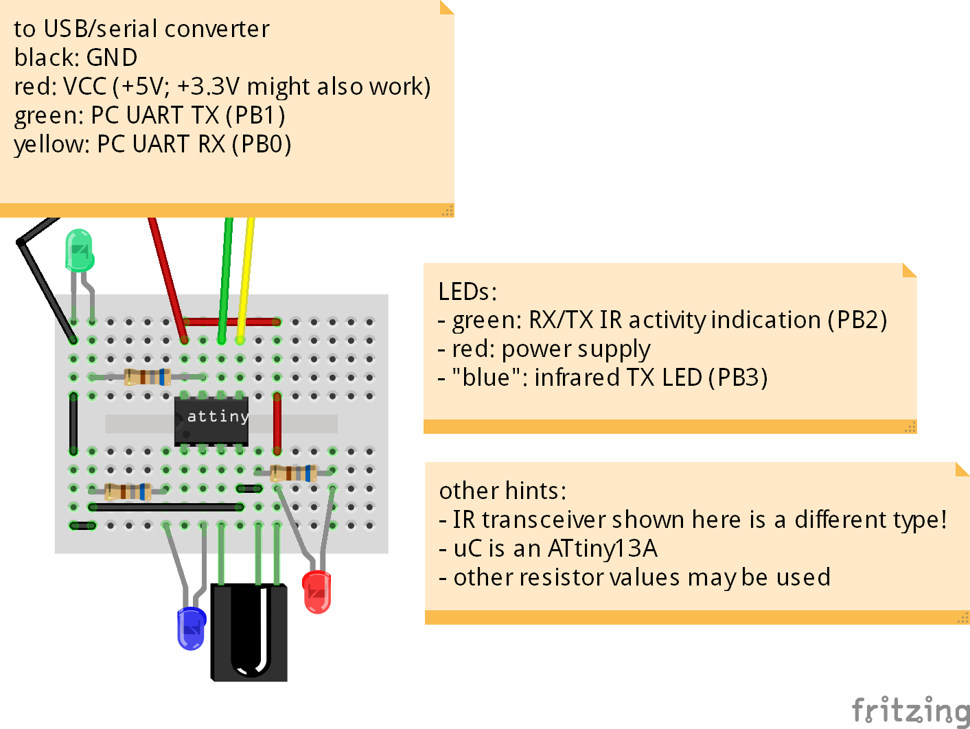
In my case, the circuitry is powered by a USB/serial converter cable which is also used to transfer the data over a virtual COM port (USB CDC interface). Please note that the converter cable of choice uses TTL voltage levels and not RS-232!
For the breadboard version see the image at the top. The Fritzing breadboard diagram looks as follows (please also pay attention to the hints inside the image):
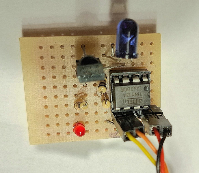
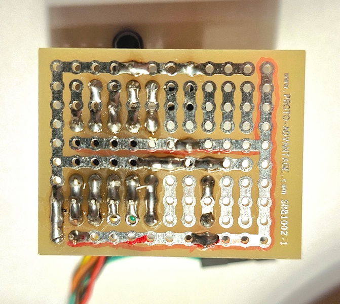
An alternative would be a solder breadboard to make something semi-permanent (the green activity LED is hidden in the next photo between the jumper wires of the USB/serial converter cable):
Since January 2026, there's a KiCAD project with all necessary files (i.e. schematic, PCB layout, pre-generated Gerber files). So instead of putting the components together on a breadboard, a PCB can be ordered. At the time of writing, some prototype PCBs (Rev. 1.0) have been ordered. But I cannot guarantee, that the design is free of bugs.
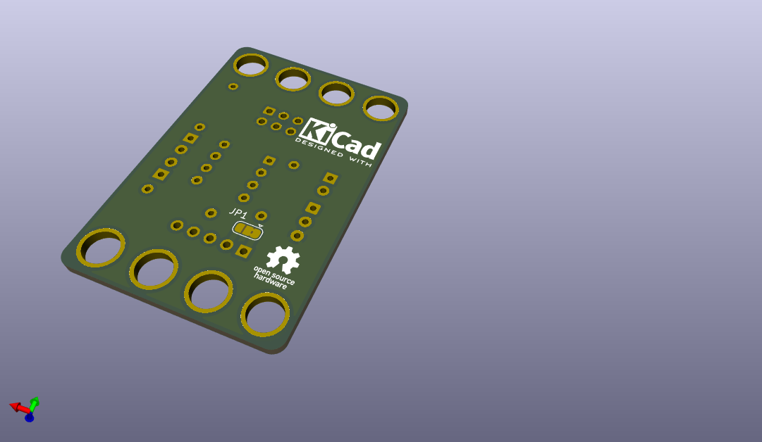
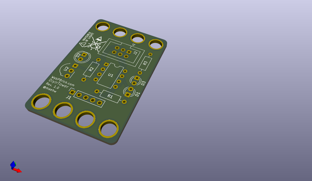
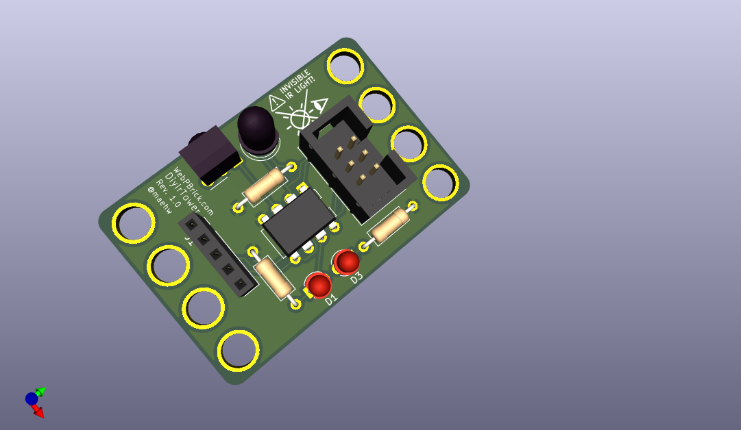
I've decided to keep through-hole components, as they are easier to solder for beginners. It may make sense to add a DIP8 IC socket for the uC. The power and activity LEDs (and their resistors) are optional, as is the ISP header for initially flashing the IC. So a setup with the minimum of components would look like this:
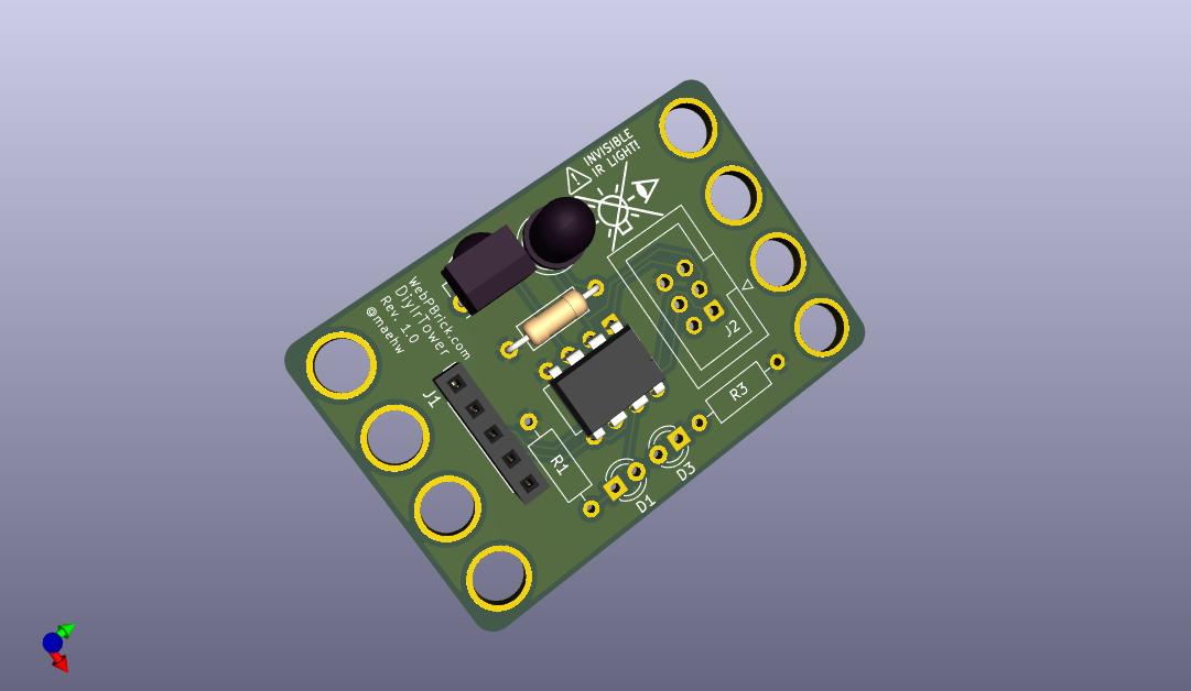
By the way, I'd choose a rectangular connector for J1. Also, you'll have to bend the TX photo diode D2 sideways, so that it points to the same side as the IR receiver IC.
Find the productive firmware in folder ./firmware.
gcc-avr (other build toolchains may work as well)avrdude: program for downloading and uploading the on-chip memories of AVR microcontrollers (or another similar tool)To build, run:
avr-gcc -g -Wall -Os -mmcu=attiny13a -o main.elf main.c(Append the verbosity flag -v to see what's going on behind the scenes.)
Want to check if it will it fit into the internal flash?
avr-size main.elf
   text	   data	    bss	    dec	    hex	filename
    776	      0	      7	    783	    30f	main.elf
Make sure to burn the microcontrollers fuses so that
Reading fuses with avrdude (and in this case an ehajo-isp in-system programmer):
avrdude -c ehajo-isp -p t13a -U hfuse:r:-:h -U lfuse:r:-:hThe default values for the two fuse bytes of the ATtiny13A are 0xff (high), 0x6a (low). The required settings however are: 0xff (high), 0x7a (low). Writing fuses with avrdude:
avrdude -c ehajo-isp -p t13a -U hfuse:w:0xff:m -U lfuse:w:0x7a:m(Hint: If the avrdude version being used gives "avrdude: AVR Part "t13a" not found.", try using t13 instead of t13a.)
Finally, flash the firmware:
avrdude -c ehajo-isp -p t13a -U flash:w:main.elf:ePlease note that under ./test/firmware, there are some more code files to test the assembled hardware. The commands from above can be reused, only the filename needs to be changed.
blink.c will blink the activity indication LED and hence allow to check if the LED is working and the compilation and flashing mechanisms also work.
pulsed_ir_tx.c will blink the activity indication LED and also transmit modulated infrared light at 38 kHz for 0.5 seconds and then switch the transmitter off for another 0.5 seconds. This allows to check if the fuse bytes have been set correctly or the blinking is way slower and the default CKDIV8 may not have been overwritten.
serial_echo.c will echo the serially received UART characters. Please note that this example does not make use of any uC UART peripheral but only relies upon GPIO pin edge detection on the "UART" receive pin. This can be used with any terminal emulator that works with serial devices or with the Python script /test/scripts/serial_coms.py to send and receive binary data:
$ python serial_coms.py -h
usage: serial_coms.py [-h] serial_device data_to_send

Send binary data over serial and receive response.

positional arguments:
  serial_device  Name of the serial device (e.g., '/dev/ttyUSB0')
  data_to_send   Binary data to send in HEX format (e.g., '55FF00609F609F')

options:
  -h, --help     show this help message and exit
Example:
$ python serial_coms.py /dev/ttyUSB0 11223344
[TX] 11 22 33 44
[RX] 11 22 33 44
The same four bytes should be received that also have been transmitted before - just as you'd expect from an echo application! Check the command line output!
The following timing diagram shows four signals from top to bottom:
UART_TX_PIN: the UART transmit (=TX) signal - as sent by the PC, coming from the attached USB/serial converterIR_LED_TX_PIN: the modulated infrared transmit signal on the IR TX LED, on–off keying (OOK) modulated at 38 kHz, 38 kHz carrier is active during low periods of UART_TX_PINPHOTO_RX_PIN: the signal on the (already demodulated) infrared receiverUART_RX_PIN: the UART receive (=RX) signal - as sent by the DIY IR tower to the USB/serial converter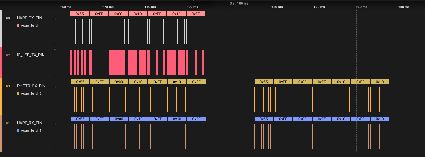
The diagram shows the message 0x55 0xFF 0x00 0x10 0xEF 0x10 0xEF being sent from the PC to the RCX (left half). It also shows the response from the RCX to the PC: 0x55 0xFF 0x00 0xEF 0x10 0xEF 0x10 (right half).
In the left half one can also see that the signal transmitted by the DIY IR tower is reflected and directly received by itself. This is due to the arrangement of IR TX LED and IR receiver - and afair can also be seen with the original IR towers. This "echo effect" must/can be handled in software!
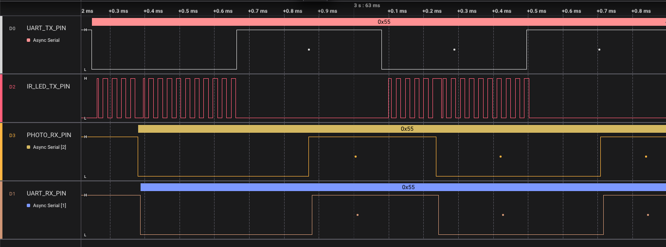
Zooming in (less time for the same screen width) reveals the delays between the signals:
LEGO® is a trademark of the LEGO Group of companies which does not sponsor, authorize or endorse this project.
| Qty | Value | Footprint | References |
|---|---|---|---|
| 3 | 680 | Resistor_THT:R_Axial_DIN0207_L6.3mm_D2.5mm_P10.16mm_Horizontal | R1, R2, R3 |
| 2 | brick-1x4 | brick-4_9id-6_0od:brick-1x4 | MH, MH |
| 1 | ACT LED | LED_THT:LED_D3.0mm | D1 |
| 1 | ATtiny13-20P | Package_DIP:DIP-8_W7.62mm | U1 |
| 1 | AVR-ISP-6 | Connector_IDC:IDC-Header_2x03_P2.54mm_Vertical | J2 |
| 1 | Conn_01x05 | Connector_PinSocket_2.54mm:PinSocket_1x05_P2.54mm_Vertical | J1 |
| 1 | LOGO | IrLed:Danger_4mm | G*** |
| 1 | LOGO | IrLed:DontStareIntoLight_9.0mm | G*** |
| 1 | POWER LED | LED_THT:LED_D3.0mm | D3 |
| 1 | SolderJumper_3_Bridged12 | Jumper:SolderJumper-3_P1.3mm_Bridged2Bar12_RoundedPad1.0x1.5mm | JP1 |
| 1 | TSAL6200 | IrLed:LED_D5.0mm_IRBlue | D2 |
| 1 | TSOP43xx | OptoDevice:Vishay_MOLD-3Pin | U2 |
The 15 most common of 17 parts.

sini6a/spotwelder
An easy-to-assemble, through-hole spot welder capable of switching high currents for welding nickel strip to lithium-ion cells. Controlled by an ATtiny13 microcontroller.

dmitry131131/Trasser
Трассерная насадка для игры в страйкбол. Подсвечивает специальные трассирующие шары при вылете из ствола при помощи УФ подсветки, а также иммитирует вспышку выстрела.


DmaEvilCorp/MoodeAudioBuild
Case Hammond 1455T2202BK (220x165x51.5mm) black aluminium. Front and back are in plastic, much easier for working. I've used FrontPanel from Schaeffer to make the design.


Susensio/soft-starter
Arduino project for soft start led strips, imitating incandescent bulbs

It measures 32 × 48 mm and has 2 copper layers, 1.6 mm thick.
17 parts, built around the ATTINY13-20PU and TSAL6200. The full list of its parts is on this page, with links to each part's symbol and footprint where PCBKit's library has them.
From the maehw/DiyIrTower repository on GitHub, at the commit this page was made from: the board is pcb/DiyIrTower.kicad_pcb and its schematic pcb/DiyIrTower.kicad_sch. PCBKit opens the board in the browser, with nothing to install.
Its repository publishes it under the GPL-3.0 licence: you may reuse it on that licence's terms (keep the author's notice, and for a copyleft licence share your changes alike).