

2 layers33 × 51.6 mm
 m9aertner/ATtiny-PinKeepAlive
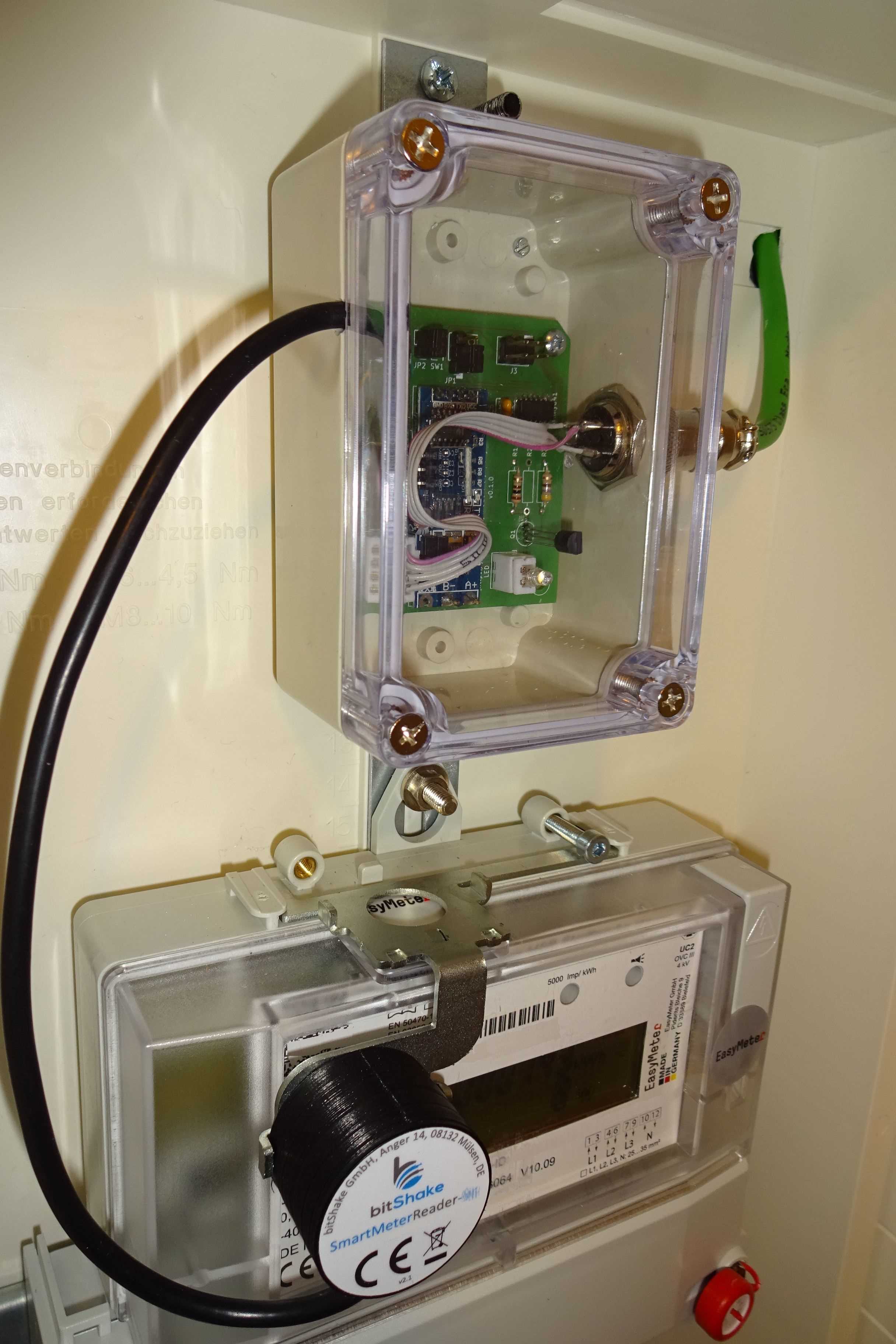
Flash in the PIN for my utility electricity meter via white LED, then keep the PIN active by flashing the LED briefly every 100 seconds.
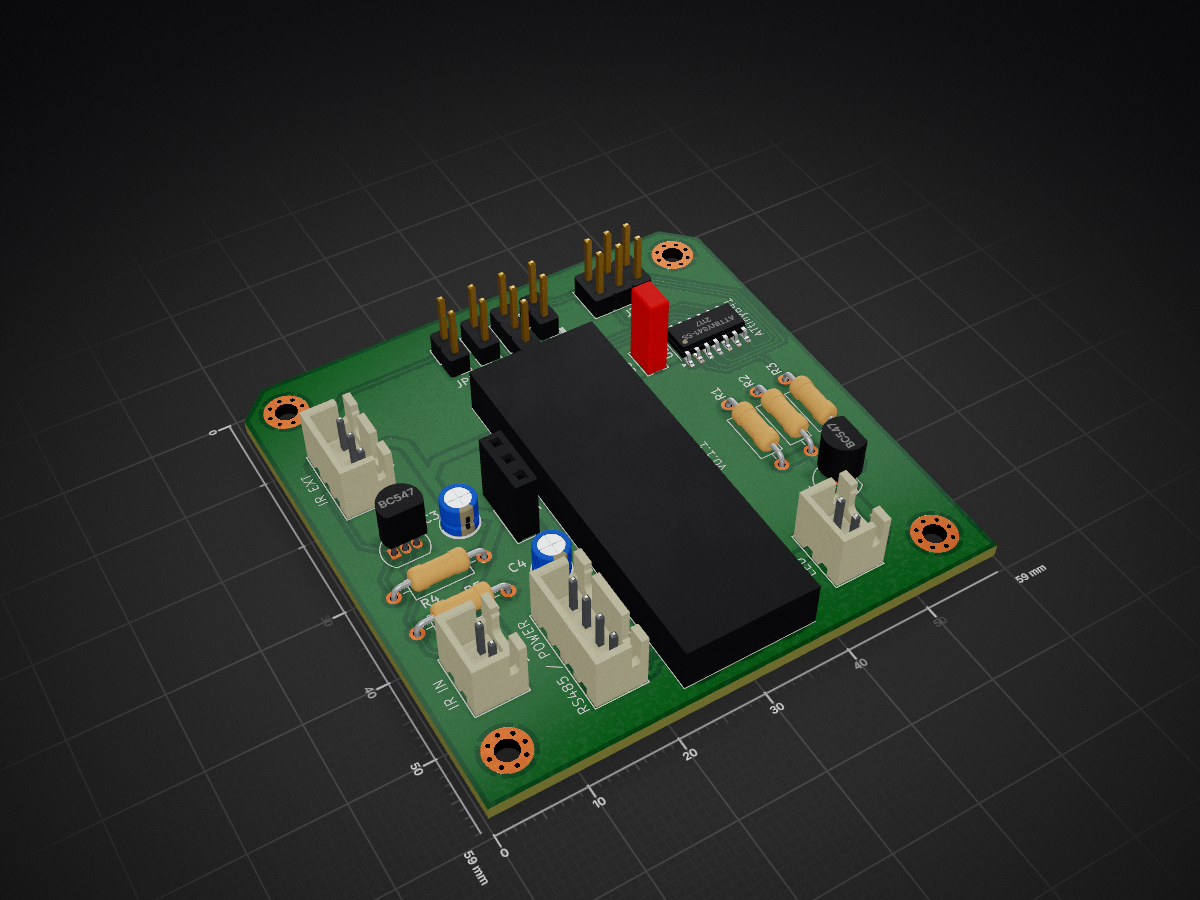
PinKeepAlive is an open-source printed circuit board by m9aertner, from the m9aertner/ATtiny-PinKeepAlive repository on GitHub, published under the MIT licence. It is a 2-layer board of 59 × 59 mm with 26 parts on 25 nets, routed with 238 tracks and 0 vias.
It is built around the ATTINY841-SSU and BC547. Its parts include 7 connectors, 5 resistors, 3 capacitors, 2 ICs and 2 transistors. It belongs with the AVR (ATmega, ATtiny) boards of this library.
Flash in the PIN for my utility electricity meter via white LED, then keep the PIN active by flashing the LED briefly every 100 seconds.
In parallel, read INFO-DSS SML datagrams via IR diode input, decode for a number of OBIS codes and expose the received values via Modbus RTU over a serial line, in my case RS-485.
The electricity power meter supplied by my local power company came mis-configured so there's no way to enable extended INFO-DSS IR datagrams permanently. The respective menu item has been configured away. Thank you very much!
After PIN entry, the extended datagrams do appear, but only for 120 seconds. After that, the unit falls back to basic datagrams again, requiring another PIN entry. Alternatively, we just simulate some activity so that the 120 second window does not close. By repeated light signals, we're keeping the unit in "extended" mode, so to say.
Without the PIN, my meter emits 1.8.0 and 2.8.0 with kWh resolution only (xxx000 W) and does not emit instantaneous power at all. After PIN entry, all three values are emitted and with Watt granularity.
A button is connected to a small microcontroller (ATtiny841) and makes a LED light up when pressed. The button is de-bounced so that a minimum LED "on" duration of around half a second is maintained. The button can be pressed for longer, extending the "on" period, which enables entry of "long" press light impulses.
In short, this function converts the error-prone manual flashing contraption to simple button presses.
Upon reset, the microcontroller enters austomatic mode. It remains in automatic mode unless the button is pressed. In automatic mode, the unit first
Then, for each of the (four) digits of the PIN,
As we do not have any feedback from the meter (neither IR nor visual) we can do nothing but try and wait for a similar amount of time. Note this cannot be super reliable. If the period is set too short, we're bumping up the current digit too much and if we wait for too long we can skip a digit, causing one or more spurious 0 digits.
The PIN is hard-coded in the source code / microcontroller. To define the PIN, copy file meterpin-sample.h to meterpin.h and adjust that copy to your PIN. Then build and upload. Setting the PIN to an empty string disables PIN entry, leaving only the Modbus-RTU function, see below.
After the automatic PIN entry or the last button press, the unit waits for 100 seconds, then emits a half-second LED flash and repeats. Pressing the button interrupts this waiting period and causes an immediate flash.
This short flash once in a while simulates some activity to the power meter so it does not ever reach the 120 second (2 minute) PIN timeout.
Consequently, the extended SML datagrams continue to be emitted. Mission accomplished.
One reviewer suggested to enter the PIN again, regularly, to guard against unexpected meter resets and/or unexpected microcontroller resets. So, after about 20 minutes, the unit now waits for a bit longer than the keep-alive period (130s, extended wait period), then blinks in the PIN again.
I still have not found the reason why anybody would want to configure away the option to emit extended datagrams permanently. What's the purpose?!
While my unit is an Easymeter Q3A, I believe there may be other types of meters with similar (stupid?) config options.
The unit's address is fixed to 0x09. Function code 0x04 (Read Input Registers) is the only function code supported.
Four values are exposed. Each value is a 32bit value, readable through two consecutive registers.
| Address | Content | Unit | Data type |
|---|---|---|---|
| 256, 257 | Version number | 32 bit unsigned integer | |
| 258, 259 | 1-0:1.8.0 Positive active energy (A+) total | Wh | 32 bit unsigned integer |
| 260, 261 | 1-0:2.8.0 Negative active energy (A+) total | Wh | 32 bit unsigned integer |
| 262, 263 | 1-0:16.7.0 Sum active instantaneous power (A+ - A-) | W | 32 bit signed integer |
Example readout using "modpoll" (https://www.modbusdriver.com/modpoll.html):
modpoll -t 3:int -a 9 -0 -r 256 -c 4 -i -1 -b 115200 -s 2 COM6

modpoll -t 3:hex -a 9 -0 -r 258 -c 6    -1 -b 115200 -s 2 COM6
The SML decoder accepts 64-bit raw values internally, but after application of the "scaler" it is expected that the resulting value fits into 32 bits. Indeed my unit always uses an 8-octet fixed-length zero-padded integer representation for all measurement values:
07 01 00 01 08 00 FF                1–0:1.8.0
62 1e                               Unit
52 03                               Scaler 10^3
59 00 00 00 01 18 CB 47 05 0x118CB4705 <=> 4710942469, scaled to 471094 Wh, displayed on the unit as 471 kWhI've prepared the schematics and a PCB using KiCad 8.0.2. Find respective project files under the kicad/ folder:
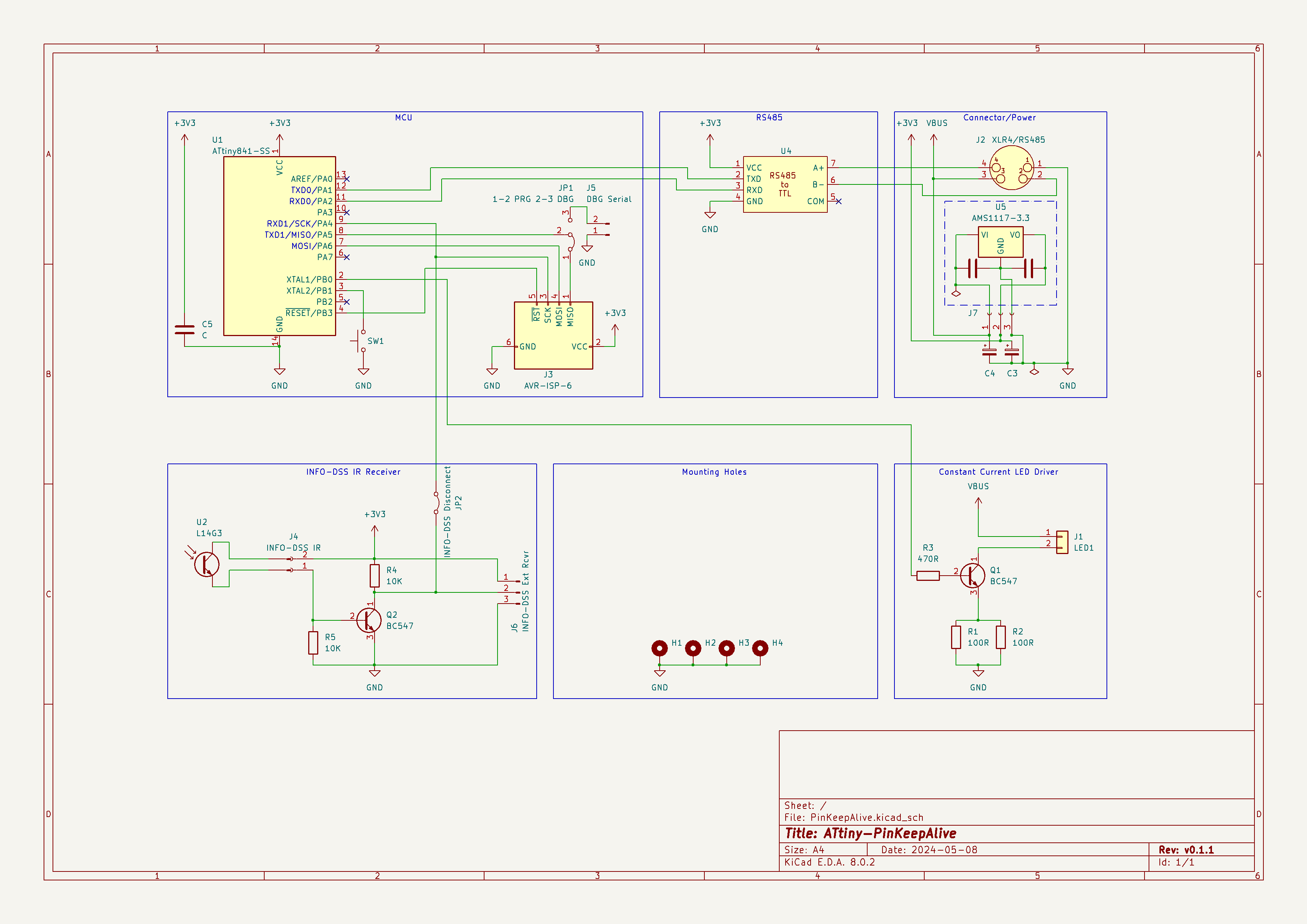
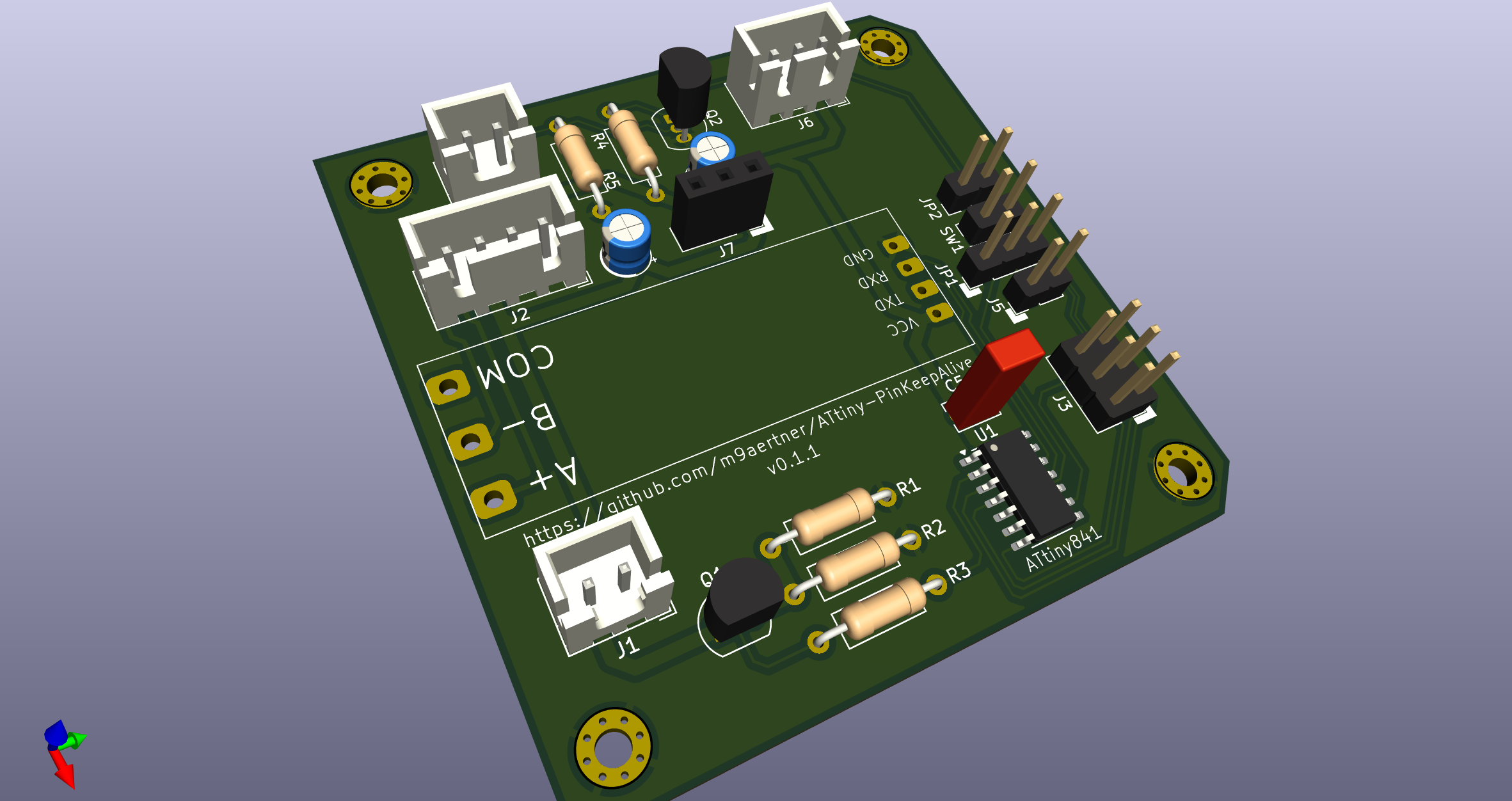
DIGIT_GAP2_TICKS in code and re-try.| Qty | Value | Footprint | References |
|---|---|---|---|
| 4 | MountingHole_Pad | MountingHole:MountingHole_2.5mm_Pad_Via | H1, H2, H3, H4 |
| 2 | 100R | Resistor_THT:R_Axial_DIN0207_L6.3mm_D2.5mm_P10.16mm_Horizontal | R1, R2 |
| 2 | 10K | Resistor_THT:R_Axial_DIN0207_L6.3mm_D2.5mm_P10.16mm_Horizontal | R4, R5 |
| 2 | 47µ | Capacitor_THT:CP_Radial_D4.0mm_P1.50mm | C3, C4 |
| 2 | BC547 | Package_TO_SOT_THT:TO-92_Inline | Q1, Q2 |
| 1 | 1-2 PRG 2-3 DBG | Connector_PinHeader_2.54mm:PinHeader_1x03_P2.54mm_Vertical | JP1 |
| 1 | 470R | Resistor_THT:R_Axial_DIN0207_L6.3mm_D2.5mm_P10.16mm_Horizontal | R3 |
| 1 | ATtiny841-SS | Package_SO:SOIC-14_3.9x8.7mm_P1.27mm | U1 |
| 1 | AVR-ISP-6 | Connector_PinHeader_2.54mm:PinHeader_2x03_P2.54mm_Vertical | J3 |
| 1 | C | Capacitor_THT:C_Rect_L4.0mm_W2.5mm_P2.50mm | C5 |
| 1 | Conn_01x03_Socket | Connector_PinSocket_2.54mm:PinSocket_1x03_P2.54mm_Vertical | J7 |
| 1 | DBG Serial | Connector_PinHeader_2.54mm:PinHeader_1x02_P2.54mm_Vertical | J5 |
| 1 | INFO-DSS Disconnect | Connector_PinHeader_2.54mm:PinHeader_1x02_P2.54mm_Vertical | JP2 |
| 1 | INFO-DSS Ext Rcvr | Connector_JST:JST_XH_B3B-XH-A_1x03_P2.50mm_Vertical | J6 |
| 1 | INFO-DSS IR | Connector_JST:JST_XH_B2B-XH-A_1x02_P2.50mm_Vertical | J4 |
| 1 | LED1 | Connector_JST:JST_XH_B2B-XH-A_1x02_P2.50mm_Vertical | J1 |
| 1 | XLR4/RS485 | Connector_JST:JST_XH_B4B-XH-A_1x04_P2.50mm_Vertical | J2 |
| 1 | ~ | Connector_PinHeader_2.54mm:PinHeader_2x01_P2.54mm_Vertical | SW1 |
| 1 | ~ | RS485toTTL:RS485toTTL-THT | U4 |


Franzininho/Franzininho-Tiny
Repositório para Franzininho Tiny - Uma placa com attiny841 da família Franzinho


BarnabyShearer/pcb_workshop_sensor
Simple lowpower MSP and Temp sensor PCB for a PCB design workshop.

It measures 59 × 59 mm and has 2 copper layers, 1.6 mm thick.
26 parts, built around the ATTINY841-SSU and BC547. The full list of its parts is on this page, with links to each part's symbol and footprint where PCBKit's library has them.
From the m9aertner/ATtiny-PinKeepAlive repository on GitHub, at the commit this page was made from: the board is kicad/PinKeepAlive.kicad_pcb and its schematic kicad/PinKeepAlive.kicad_sch. PCBKit opens the board in the browser, with nothing to install.
Its repository publishes it under the MIT licence: you may reuse it on that licence's terms (keep the author's notice, and for a copyleft licence share your changes alike).