4 layers160 × 90 mm

 lwolf/srvant-board2
[WIP] Carrier board for the CM4 with BMC
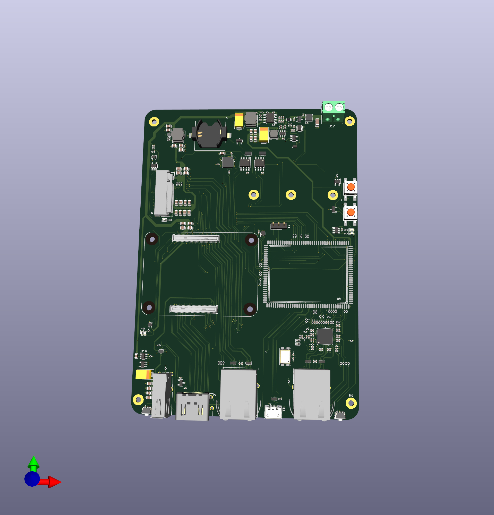
Srvant mk2 is an open-source printed circuit board by lwolf, from the lwolf/srvant-board repository on GitHub. It is a 6-layer board of 100 × 220 mm with 276 parts on 390 nets, routed with 2,676 tracks and 575 vias.
It is built around the 74LVC1G07SE-7-MS, KSZ9131RNXI-TR and AP63205WU, with the 74AHC1G08GW, PCF85063AT/AAZ and 74AHC1G04SE among its other parts. Its parts include 113 capacitors, 68 resistors, 22 ICs, 11 diodes and 8 connectors. It belongs with the computers and single-board computers boards and the NXP (LPC, Kinetis, i.MX RT) and Raspberry Pi (Linux) boards of this library.


| :warning: WARNING |
|---|
| This is a work-in-progress. No final board have been produced yet. Any part of the schematic and/or PCB could be wrong. |
Design of the carrier board for the Raspberry Pi CM4. The main distinction from existing boards is the presence of the BMC (Baseboard Management Controller) which supposed to monitor and control the HOST, allowing the board to act as a real "server".
BMC using lots of GPIO controls the HOST: power cycle, terminal access, switches USB into OTG for flushing.
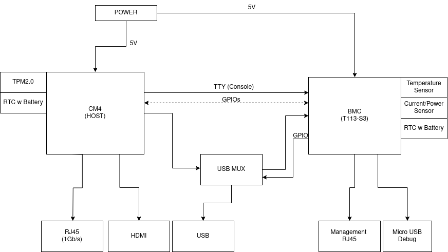
BMC is based on the Allwinner T113 S3 SoM link to aliexpress.
THere are separate 5v rails for host and BMC. The host one is based on AP64501SP (5V 5A), while BMC is based on AP63205WU (5V 2A). BMC is always on. Host is being powered either by a signal from BMC or by shortening a jumper.
Main power goes through the shunt resistor connected to the power sensor (INA219A). The value is available to BMC using i2c bus.
Host has a following connectors:
BMC has a following connectors:
There is a connection between BMC and HOST using USB to allow flushing the HOST remotely. Since CM4 has only a single usb line, it is connected to the MUX (FSUSB42MUX) in a similar way it is done in the CM4IO board, but instead of switching client mode to microUSB, it goes to BMC.
RTC is based on PCF85063AT chip. There are two of them, one for each CPU. Even though t133-s3 has on-board RTC, it is not exposed from the SOM and reference schematic uses external one. Both chips are powered by 3.3v coming from BMC and coin cell battery.
| Qty | Value | Footprint | References |
|---|---|---|---|
| 52 | 100n | Capacitor_SMD:C_0402_1005Metric | C2, C14, C15, C29, C31, C32, C34, C35, C102, C104, C105, C111, C112, C122, C123, C126 +36 |
| 34 | 10u | Capacitor_SMD:C_0805_2012Metric | C10, C11, C12, C13, C18, C19, C106, C107, C108, C109, C110, C116, C117, C118, C119, C121 +18 |
| 22 | 10K | Resistor_SMD:R_0402_1005Metric | R10, R11, R12, R24, R25, R30, R34, R42, R44, R46, R51, R54, R56, R61, R68, R71 +6 |
| 13 | 22R | Resistor_SMD:R_0402_1005Metric | R18, R19, R20, R21, R22, R23, R36, R37, R38, R39, R40, R41, R62 |
| 12 | 10u | Capacitor_SMD:C_0402_1005Metric | C30, C33, C49, C52, C53, C54, C55, C56, C83, C85, C92, C124 |
| 10 | 1K | Resistor_SMD:R_0402_1005Metric | R13, R14, R28, R33, R47, R48, R50, R60, R65, R70 |
| 7 | SolderJumper_2_Open | Jumper:SolderJumper-2_P1.3mm_Open_RoundedPad1.0x1.5mm | JP1, JP2, JP3, JP4, JP5, JP6, JP7 |
| 5 | 1u | Capacitor_SMD:C_0402_1005Metric | C42, C86, C93, C94, C125 |
| 5 | 220R | Resistor_SMD:R_0402_1005Metric | FB1, FB2, FB4, FB5, FB8 |
| 5 | TPD4EUSB30 | Package_SON:USON-10_2.5x1.0mm_P0.5mm | U7, U10, U11, U19, U20 |
| 4 | 100u | Capacitor_Tantalum_SMD:CP_EIA-7343-31_Kemet-D | C24, C28, C74, C120 |
| 4 | MountingHole | MountingHole:MountingHole_2.5mm_Pad_TopOnly | H4, H5, H6, H7 |
| 4 | PCIe_nRST | TestPoint:TestPoint_Pad_D1.0mm | TP15, TP20, TP21, TP22 |
| 3 | 10R | Resistor_SMD:R_0402_1005Metric | R7, R8, R16 |
| 3 | 1n | Capacitor_SMD:C_0402_1005Metric | C84, C91, C99 |
| 3 | 330R | Resistor_SMD:R_0402_1005Metric | R15, R17, R74 |
| 3 | Conn_01x03 | Connector_PinHeader_2.54mm:PinHeader_1x03_P2.54mm_Vertical | J3, J13, J14 |
| 3 | LED | LED_SMD:LED_0603_1608Metric | D3, D4, D10 |
| 2 | +5v HOST | TestPoint:TestPoint_Pad_2.0x2.0mm | TP2, TP23 |
| 2 | 1200p | Capacitor_SMD:C_0402_1005Metric | C17, C114 |
| 2 | 12K | Resistor_SMD:R_0402_1005Metric | R1, R63 |
| 2 | 15K | Resistor_SMD:R_0402_1005Metric | R53, R69 |
| 2 | 1N4148 | Diode_SMD:D_SOD-523 | D5, D6 |
| 2 | 3.3K | Resistor_SMD:R_0402_1005Metric | R75, R76 |
| 2 | 3.3µH | Inductor_SMD:L_Bourns_SRN6045TA | L2, L4 |
| 2 | 470R | Resistor_SMD:R_0402_1005Metric | R66, R67 |
| 2 | 510K | Resistor_SMD:R_0402_1005Metric | R57, R59 |
| 2 | 74AHC1G08 | Package_TO_SOT_SMD:SOT-23-5 | U24, U25 |
| 2 | 74LVC1G07SE-7 | Package_TO_SOT_SMD:SOT-353_SC-70-5 | U18, U21 |
| 2 | AP64501SP-13 | Package_SO:SOIC-8-1EP_3.9x4.9mm_P1.27mm_EP2.95x4.9mm_Mask2.71x3.4mm_ThermalVias | U2, U26 |
| 2 | ARJM11 | Connector_RJ:RJ45_Wuerth_7499111446_Horizontal | J5, J9 |
| 2 | PCF85063AT/AAZ | Package_SO:SOIC-8_3.9x4.9mm_P1.27mm | U6, U17 |
| 2 | X32K768S301 | PCM_Crystal_AKL:Crystal_SMD_2012-2Pin_2.0x1.2mm | Y1, Y3 |
| 1 | +5v BMC | TestPoint:TestPoint_Pad_2.0x2.0mm | TP16 |
| 1 | 0.005R | Resistor_SMD:R_0805_2012Metric | R2 |
| 1 | 100K | Resistor_SMD:R_0402_1005Metric | R79 |
| 1 | 100n | Capacitor_SMD:C_1206_3216Metric | C1 |
| 1 | 115K | Resistor_SMD:R_0402_1005Metric | R5 |
| 1 | 1v2 | TestPoint:TestPoint_Pad_D1.0mm | TP4 |
| 1 | 20K | Resistor_SMD:R_0402_1005Metric | R4 |
| 1 | 22.1K | Resistor_SMD:R_0402_1005Metric | R6 |
| 1 | 3.3v BMC | TestPoint:TestPoint_Pad_D1.0mm | TP5 |
| 1 | 4.7µH | Inductor_SMD:L_Bourns-SRN4018 | L1 |
| 1 | 47K | Resistor_SMD:R_0402_1005Metric | R64 |
| 1 | 5v OTG | TestPoint:TestPoint_Pad_D1.0mm | TP17 |
| 1 | 6.04K | Resistor_SMD:R_0402_1005Metric | R29 |
| 1 | 74AHC1G04 | Package_TO_SOT_SMD:SOT-23-5 | U13 |
| 1 | 74AHC1G32 | Package_TO_SOT_SMD:SOT-23-5 | U3 |
| 1 | AP22653W6 | Package_TO_SOT_SMD:SOT-23-6 | U14 |
| 1 | AP63205WU | Package_TO_SOT_SMD:TSOT-23-6 | U1 |
| 1 | ASEK-32.768KHZ-L-R-T | Crystal:Crystal_SMD_3225-4Pin_3.2x2.5mm | U8 |
| 1 | BAT54C-7-F | Package_TO_SOT_SMD:SOT-23 | D2 |
| 1 | Battery_Cell | footprints:battery-S8411-45R | BT1 |
| 1 | Bus_M.2_Socket_M | footprints:M.2 M Key socket_rpi | J8 |
| 1 | CK | TestPoint:TestPoint_Pad_D1.0mm | TP13 |
| 1 | ComputeModule4 | CM4IO:Raspberry-Pi-4-Compute-Module | Module1 |
| 1 | Conn_01x02 | Connector_PinHeader_2.54mm:PinHeader_1x02_P2.54mm_Vertical | J2 |
| 1 | DI | TestPoint:TestPoint_Pad_D1.0mm | TP8 |
| 1 | DMP3013SFV-7 | Package_SON:Diodes_PowerDI3333-8 | Q1 |
| 1 | DMP3098LQ-7 | DMP3098L:SOT-23_DMP3098LQ_DIO | MOSFET1 |
| 1 | DO | TestPoint:TestPoint_Pad_D1.0mm | TP9 |
| 1 | FEL | button-1571563-4:SW4_FSM-5P23_TEC | SW2 |
| 1 | FSUSB42MUX | Package_SO:MSOP-10_3x3mm_P0.5mm | U15 |
| 1 | GND | TestPoint:TestPoint_Pad_D1.0mm | TP3 |
| 1 | HOST_RESET | footprints:button-SW_TL3340AF160QG | SW4 |
| 1 | INA219AxDCN | Package_TO_SOT_SMD:SOT-23-8 | U4 |
| 1 | KSZ9131RNXI-TR | KSZ9131RNXI-TR:QFN48_NX_MCH | U12 |
| 1 | LED Green | LED_SMD:LED_0603_1608Metric | D7 |
| 1 | LED Red | LED_SMD:LED_0603_1608Metric | D8 |
| 1 | MMBZ5242BLT3G | MMBZ5240BLT1:SOT-23-3_1P4X3P040_ONS | D1 |
| 1 | MS | TestPoint:TestPoint_Pad_D1.0mm | TP7 |
| 1 | NMI_N | TestPoint:TestPoint_Pad_D1.0mm | TP19 |
| 1 | PCIe_nCLKREQ | TestPoint:TestPoint_Pad_D1.0mm | TP14 |
| 1 | PESD2USB5UX-T | Package_TO_SOT_SMD:SOT-23 | D9 |
| 1 | PHY_AVDDH(3.3v) | TestPoint:TestPoint_Pad_D1.0mm | TP10 |
| 1 | POWER | LED_SMD:LED_0603_1608Metric | D11 |
| 1 | POWER | footprints:button-SW_TL3340AF160QG | SW1 |
| 1 | RST | button-1571563-4:SW4_FSM-5P23_TEC | SW3 |
| 1 | SLB9670VQ20FW785XTMA1 | QFN32_SLB9670VQ20FW785XTMA1_INF:QFN32_SLB9670VQ20FW785XTMA1_INF | U23 |
| 1 | Screw_Terminal_01x02 | TerminalBlock:TerminalBlock_bornier-2_P5.08mm | J12 |
The 269 most common of 276 parts.
It measures 100 × 220 mm and has 6 copper layers, 1.61 mm thick.
276 parts, built around the 74LVC1G07SE-7-MS, KSZ9131RNXI-TR, AP63205WU and 74AHC1G08GW. The full list of its parts is on this page, with links to each part's symbol and footprint where PCBKit's library has them.
From the lwolf/srvant-board repository on GitHub, at the commit this page was made from: the board is kicad/mk2/srvant-mk2/srvant-mk2.kicad_pcb and its schematic kicad/mk2/srvant-mk2/bmc.kicad_sch. PCBKit opens the board in the browser, with nothing to install.
Its repository states no licence, so its author keeps all rights: ask lwolf before reusing the design.


NBence0/JedlikBots
Welcome to the official GitHub page of JedlikBots! 🎓🤖 We are the dedicated team of software development and robotics students from the Jedlik Ányos Technical School in Győr, Hungary.


sanctuary-systems-com/rpi-cm5io-mini-itx
A mini ITX board with PCIe x16 based on the Raspberry Pi Comput Module 5 IO board