
2 layers45.7 × 45.7 mm

 luoyi99/Techin514_final_project
Final project sensor pcb is an open-source printed circuit board by luoyi99, from the luoyi99/Techin514_final_project repository on GitHub. It is a 2-layer board of 68.6 × 48.3 mm with 13 parts on 32 nets, routed with 54 tracks and 0 vias.
It is built around the MPU-6050. Its parts include 4 capacitors, 3 resistors, 2 ICs, 1 diode and 1 connector. It belongs with the sensors and measurement boards of this library.
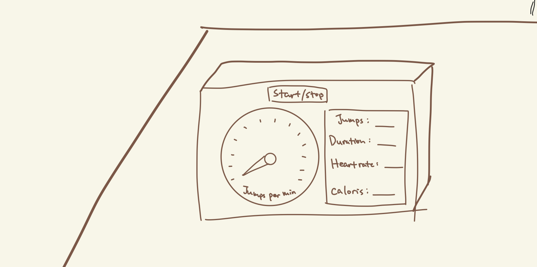
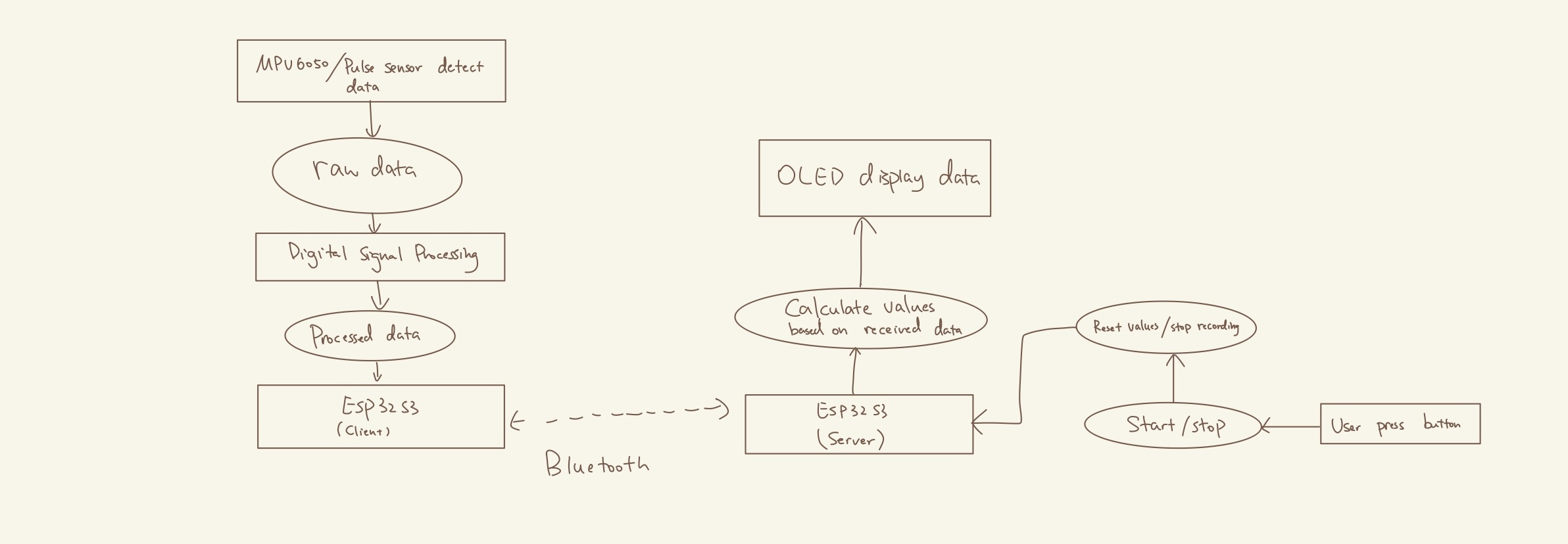
A basic fitness tracker that monitors and displays key metrics like the number of jumps, rate (jumps per minute), heart rate and calories burned. The project integrates an accelerometer for motion sensing, a pulse sensor for heart rate monitoring, a display mechanism using screen and stepper motor-driven gauge needle, and a button for reset.

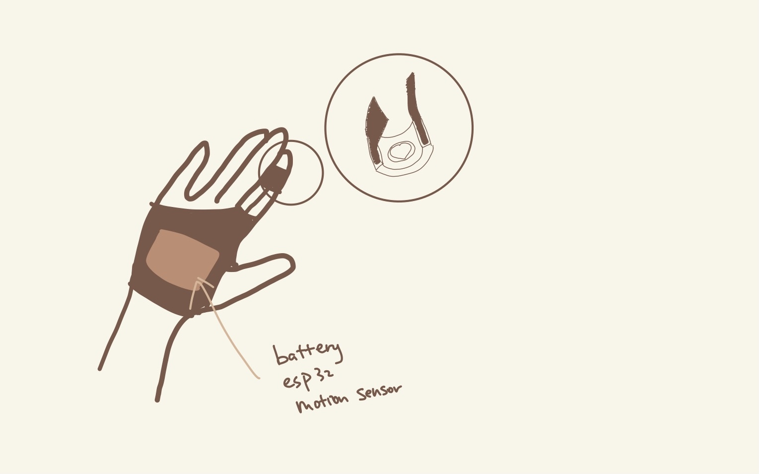
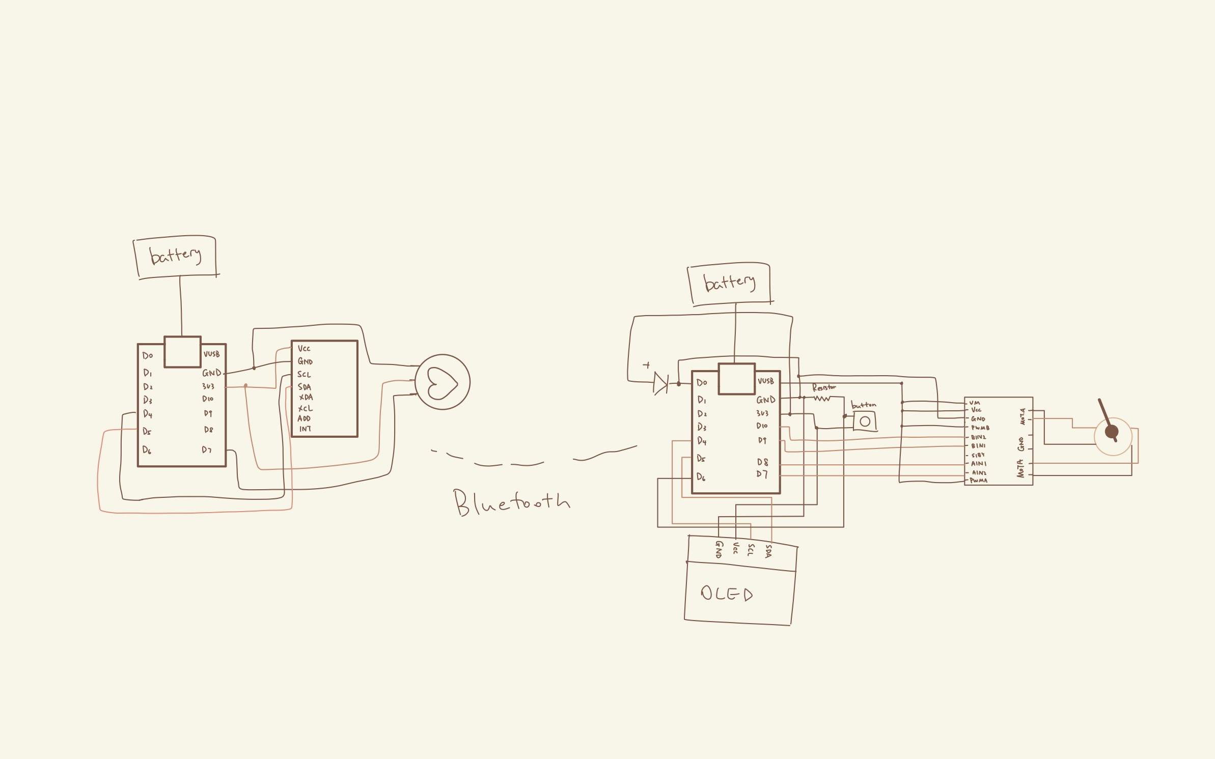
The sensor device will include a MPU6050 motion sensor, a pulse sensor, a ESP32S3 processor and a battery. The components will be sewed on a glove so users can wear it when doing jumping jacks without worrying it to fall down.
The display device will include a ESP32S3 processor, a battery, a OLED screen, a button, a LED, a stepper motor driver breakout board (Adafruit TB6612 1.2A DC/Stepper Motor Driver Breakout Board) and a stepper-motor-driven gauge needle (x27.168).
| Qty | Value | Footprint | References |
|---|---|---|---|
| 3 | 0.1uf | Capacitor_SMD:C_0805_2012Metric_Pad1.18x1.45mm_HandSolder | C5, C6, C7 |
| 2 | 4.7k | Resistor_SMD:R_0805_2012Metric_Pad1.20x1.40mm_HandSolder | R2, R3 |
| 1 | 1k | Resistor_SMD:R_0805_2012Metric_Pad1.20x1.40mm_HandSolder | R1 |
| 1 | 220pf | Capacitor_SMD:C_0805_2012Metric_Pad1.18x1.45mm_HandSolder | C4 |
| 1 | Battery_Cell | Battery:BatteryHolder_Keystone_103_1x20mm | BT1 |
| 1 | LED | LED_SMD:LED_0805_2012Metric_Pad1.15x1.40mm_HandSolder | D1 |
| 1 | MPU-6050 | Sensor_Motion:InvenSense_QFN-24_4x4mm_P0.5mm | U2 |
| 1 | SEN-11574 | Pulse_Sensor:XDCR_SEN-11574 | P2 |
| 1 | SW_SPST | Button_Switch_THT:SW_PUSH-12mm | SW1 |
| 1 | ~ | XIAO ESP32S3:XIAO_ESP32_SENSE | U1 |


ZhuYanzhen1/MM32_CLion
本项目是全国大学生智能车竞赛GDUT 2022年极速越野组的项目文件。采用了LQR控制器和多速率卡尔曼融合算法,并在单片机上实现。This project is the project document for the GDUT 2022 Extreme Off-Road Category of the National Student Intelligent Vehicle Competition.


victorhook/asac-fc
asac fc is an rp2040 based flight controller made for FPV drone flying


pms67/PModlet
PMOD PCB with USB-to-UART converter and IMU (MPU-6050, I2C) for FPGAs.
It measures 68.6 × 48.3 mm and has 2 copper layers, 1.6 mm thick.
13 parts, built around the MPU-6050. The full list of its parts is on this page, with links to each part's symbol and footprint where PCBKit's library has them.
From the luoyi99/Techin514_final_project repository on GitHub, at the commit this page was made from: the board is PCB/sensor_pcb/final_project_sensor_pcb.kicad_pcb and its schematic PCB/display_pcb/final_project_pcb.kicad_sch. PCBKit opens the board in the browser, with nothing to install.
Its repository states no licence, so its author keeps all rights: ask luoyi99 before reusing the design.