4 layers65 × 56.5 mm
 lukaslibar/Camera-Cooler
Cooling solution for Svbony SV705C astronomy camera.
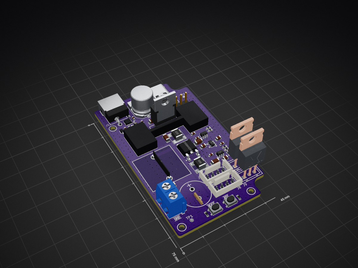
Camera Cooler is an open-source printed circuit board by lukaslibar, from the lukaslibar/Camera-Cooler repository on GitHub. It is a 4-layer board of 45 × 75 mm with 118 parts on 98 nets, routed with 592 tracks and 373 vias.
It is built around the RP2354A, TPS54202DDCR and TPS560430XDBVR-MS, with the XL4016E1, ABM8-272-T3 and TLV75533PDBVR-MS among its other parts. Its parts include 46 capacitors, 34 resistors, 8 ICs, 8 connectors and 4 diodes. It belongs with the RP2350 boards of this library.


Cooling solution for Svbony SV705C astronomy camera.
More about the project on my website.
This repository contains multiple components, each under its own license.
See the project-folder/LICENSES directory for the full license texts.
This project is an attempt to actively cool the Svbony SV7505C astronomy camera. The cooling is intended to achieve better image quality by cooling the camera sensor through the bottom PCB. With this setup, we have achieved a temperature difference of 20°C, but we are still trying to improve the results through better insulation. A major problem is condensation, and great care must be taken to avoid short circuits on the camera's bottom PCB. The PCB manufactured by JLCPCB can either be placed upside down or sealed with rubber or a similar material. The cooling system is powered by a 19V DC power supply capable of supplying at least 6 A of current.
We are currently developing the REV B PCB, which will eliminate some issues with incorrect connectors (fen connectors) and add the ability to completely disable the Peltier element (TEC) (with an additional MOSFET). At the moment, there are MicroPython example programs for controlling the device, but we are developing a C++ driver to make the system faster and more efficient. There is also a simple GUI, but the USB port currently needs to be configured manually.
PROBLEMS:
TEC
FANS
HEATSINKS
THERMAL PAD AND PASTE
THERMOMETER
INTERFACE
SCREWS
PCB assembly is quite straightforward. The only exception is soldering the XL4016E1 and its heatsink. They should first be screwed together with a small amount of thermal pad or thermal paste between them. The assembly should then be placed on the PCB and soldered in place at the same time to prevent misalignment.
First, the camera needs to be disassembled. Its top cover and upper PCB, which is connected with a short ribbon cable, need to be removed. The aluminium cooling block and the 3D-printed cooling block holder can then be assembled. The 3d printed parts screwholes should be inserted with threaded inserts with a soldering iron or simmilar tool.
Place a thermal pad on the smaller side of the cooling block. The thermal pad should be cut to the same shape as that side of the block. There is a small hole on the side of the block for the temperature sensor, which must have wires soldered to it. A longer ribbon cable should be connected to the bottom PCB. A small amount of thermal paste can be applied between the temperature sensor and the cooling block to ensure more accurate temperature readings.
The entire assembly can now be fitted into the camera enclosure so that the screw holes are properly aligned. The main fan and heatsink can then be screwed together, and the fan cable can be routed through the upper hole into the PCB enclosure. The complete fan and heatsink assembly can then be fitted into the main enclosure.
The Peltier element (TEC) needs to be fitted to the bottom of the heatsink, with thermal paste applied between the two surfaces. There are holes for its wires alongside a slit for the longer ribbon cable. The camera and the cooler can then be joined together using thermal paste between their contact surfaces. The upper camera PCB and the custom TEC driver PCB have designated positions inside the enclosure on the side. An additional fan can also be installed to cool the enclosure.
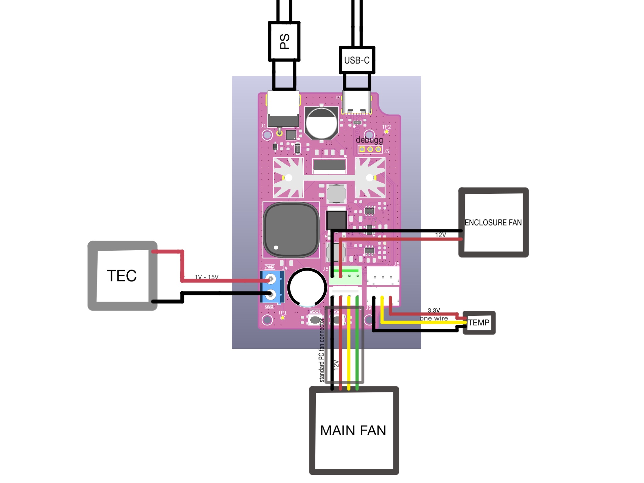 TEC driver electrical connections
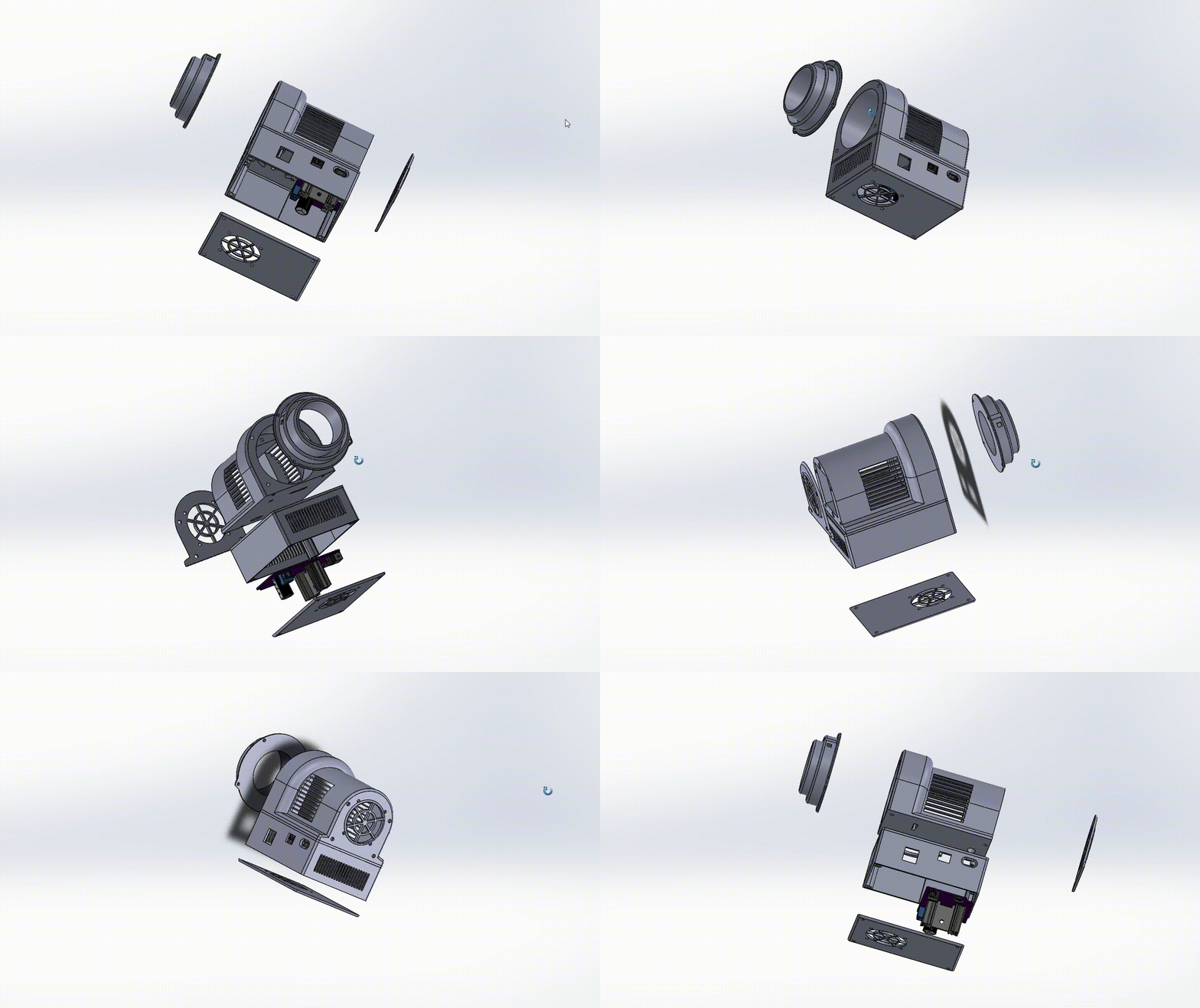 Assembly of 3d-printed parts and pcb
| Qty | Value | Footprint | References |
|---|---|---|---|
| 23 | 100n | PCM_JLCPCB:C_0603 | C2, C3, C10, C14, C21, C22, C23, C24, C25, C26, C27, C28, C29, C30, C31, C32 +7 |
| 7 | 10u | PCM_JLCPCB:C_0805 | C8, C9, C13, C34, C44, C45, C46 |
| 5 | 12k | PCM_JLCPCB:R_0603 | R3, R8, R9, R15, R16 |
| 4 | 100 | PCM_JLCPCB:R_0603 | R28, R29, R31, R32 |
| 4 | 4.7u | PCM_JLCPCB:C_0603 | C15, C16, C19, C20 |
| 4 | 5.1k | PCM_JLCPCB:R_0603 | R6, R10, R13, R14 |
| 4 | MountingHole | MountingHole:MountingHole_2.2mm_M2 | H1, H2, H3, H4 |
| 3 | 0 | PCM_JLCPCB:R_0603 | R25, R27, R34 |
| 3 | 100k | PCM_JLCPCB:R_0603 | R4, R30, R33 |
| 3 | 1k | PCM_JLCPCB:R_0603 | R17, R18, R19 |
| 3 | 1u | PCM_JLCPCB:C_1206 | C36, C37, C41 |
| 2 | 10 | PCM_JLCPCB:R_0603 | R20, R22 |
| 2 | 15p | PCM_JLCPCB:C_0603 | C17, C18 |
| 2 | 22u | PCM_JLCPCB:C_1206 | C1, C12 |
| 2 | 2510-4A | easyeda2kicad:CONN-TH_4P-P2.54_CAX_2510-4A | J5, J8 |
| 2 | 27 | PCM_JLCPCB:R_0603 | R11, R12 |
| 2 | 2N7002LT1G | Package_TO_SOT_SMD:SOT-23 | Q2, Q3 |
| 2 | NetTie_2 | NetTie:NetTie-2_SMD_Pad0.5mm | NT1, NT2 |
| 2 | TS3425BA | easyeda2kicad:SW-SMD_4P-L4.2-W3.2-P2.15-LS4.6-1 | SW1, SW2 |
| 2 | TestPoint | TestPoint:TestPoint_Pad_D1.0mm | TP1, TP2 |
| 2 | ZX-XH2.54-3PZZ | easyeda2kicad:CONN-TH_3P-P2.54_2501S-3P | J6, J9 |
| 1 | 1000u | easyeda2kicad:CAP-TH_BD12.5-P5.00-D0.6-FD | C40 |
| 1 | 10u | easyeda2kicad:IND-SMD_L6.0-W6.0_SRN6045 | L2 |
| 1 | 180k | PCM_JLCPCB:R_0603 | R23 |
| 1 | 22.1k | PCM_JLCPCB:R_0603 | R2 |
| 1 | 22u | easyeda2kicad:IND-SMD_L6.0-W6.0_SRN6045 | L1 |
| 1 | 27k | PCM_JLCPCB:R_0603 | R26 |
| 1 | 2m | PCM_Resistor_SMD_AKL:R_2512_6332Metric | R21 |
| 1 | 3.3u | easyeda2kicad:IND-SMD_L2.0-W1.6_AOTA-B201610S3R3-101-T | L3 |
| 1 | 33 | PCM_JLCPCB:R_0603 | R7 |
| 1 | 33n | PCM_JLCPCB:C_0603 | C39 |
| 1 | 4.7u | PCM_JLCPCB:C_1206 | C7 |
| 1 | 43k | PCM_JLCPCB:R_0603 | R24 |
| 1 | 470u | easyeda2kicad:CAP-SMD_BD10.0-L10.4-W10.4-LS11.2-FD | C38 |
| 1 | 47p | PCM_JLCPCB:C_0603 | C11 |
| 1 | 47u | easyeda2kicad:IND-TH_L17.8-W17.8-P13.00-D0.6 | L4 |
| 1 | 5.23k | PCM_JLCPCB:R_0603 | R5 |
| 1 | 88.7k | PCM_JLCPCB:R_0603 | R1 |
| 1 | ABM8-272-T3_C20625731 | easyeda2kicad:CRYSTAL-SMD_4P-L3.2-W2.5-BL | U8 |
| 1 | BZT52C10 | easyeda2kicad:SOD-123_L2.7-W1.6-LS3.7-RD | D2 |
| 1 | DC-044K-D025 | easyeda2kicad:DC-IN-TH_DC-044K-D025 | J1 |
| 1 | DMP3013SFV-7 | easyeda2kicad:TRANS_FDMC8010 | Q1 |
| 1 | HSE-B20254-035H-01 | easyeda2kicad:HSEB20254035H01 | HS1 |
| 1 | HX PH254-01-03-Z-L11.5 | easyeda2kicad:HDR-TH_3P-P2.54-V-M-1 | J3 |
| 1 | INA219AIDR | easyeda2kicad:SOIC-8_L4.9-W3.9-P1.27-LS6.0-BL | U9 |
| 1 | KF301-5.0-2P | easyeda2kicad:CONN-TH_P5.00_KF301-5.0-2P | J4 |
| 1 | MBR2045DCT | Package_TO_SOT_SMD:TO-252-2 | D4 |
| 1 | MCP4725A0T-E/CH | easyeda2kicad:SOT-23-6_L2.9-W1.6-P0.95-LS2.8-BL | U11 |
| 1 | PESD1IVN24-AX | easyeda2kicad:SOD-323_L1.8-W1.3-LS2.5-BI-A | D1 |
| 1 | RP2354A | easyeda2kicad:QFN-60_L7.0-W7.0-P0.40-TL-EP3.4 | U7 |
| 1 | TLV75533PDBVR | easyeda2kicad:SOT-23-5_L3.0-W1.7-P0.95-LS2.8-BR | U5 |
| 1 | TPD4E05U06DQAR_C2827646 | easyeda2kicad:USON-10_L2.5-W1.0-P0.50-BL | D3 |
| 1 | TPS54202DDCR | easyeda2kicad:SOT-23-6_L2.9-W1.6-P0.95-LS2.8-BL | U6 |
| 1 | TPS560430XDBVR | easyeda2kicad:SOT-23-6_L2.9-W1.6-P0.95-LS2.8-BL | U4 |
| 1 | TYPE-C 16PIN 2MD | easyeda2kicad:USB-C-SMD_TYPE-C-6PIN-2MD-073 | J2 |
| 1 | XL4016E1 | easyeda2kicad:TO-220-5L_L10.2-W4.5-P1.71-L | U10 |
It measures 45 × 75 mm and has 4 copper layers, 1.63 mm thick.
118 parts, built around the RP2354A, TPS54202DDCR, TPS560430XDBVR-MS and XL4016E1. The full list of its parts is on this page, with links to each part's symbol and footprint where PCBKit's library has them.
From the lukaslibar/Camera-Cooler repository on GitHub, at the commit this page was made from: the board is project-folder/hardware/electrical/KiCAD/camera_cooler.kicad_pcb and its schematic project-folder/hardware/electrical/KiCAD/camera_cooler.kicad_sch. PCBKit opens the board in the browser, with nothing to install.
Its repository states no licence, so its author keeps all rights: ask lukaslibar before reusing the design.

bogdan-kovalchuk/esp32-battery-charging-monitoring
An ESP32-based 12 V battery voltage monitor. The firmware measures battery voltage, while a Flask backend delivers notifications to a Signal group through signal-cli.

harry10086/InkWord_ESP32
An ESP32 and E-paper based low-power English vocabulary learning device.一个基于 ESP32 和墨水屏的低功耗英语单词学习设备。

thelad-dev/ESP32-USB-PWM-Board
ESP32-Firmware & Hardware für 4-Pin-PWM-Lüfter: Duty-Steuerung, Tacho/RPM, serielle CLI.

DD1SB/ARDF-TX
Date: 2026-10-15. Engineering review only; unbuilt and unenergized. Open RF80.kicadpro, schematic and native PCB in KiCad10.0.6. Three primary PCBs and the separate VHF true-AM design are unchanged.

cherry-embedded/HSCanT-hardware
HSCanT is a USB to 4-channel CAN FD tool designed based on the HPM5321 chip.

