2 layers92 × 57 mm

 luftaquila/fsk-timekeeper
Wireless timing system for Formula Student Korea dynamic events
Fsk timekeeper is an open-source printed circuit board by luftaquila, from the luftaquila/fsk-timekeeper repository on GitHub. It is a 2-layer board of 92 × 57 mm with 27 parts on 36 nets, routed with 81 tracks and 75 vias.
It is built around the TPS61040DBV, B5819W and BAT54S. Its parts include 8 capacitors, 4 resistors, 4 ICs, 2 diodes and 1 connector. It belongs with the nRF52 and nRF5x boards of this library.


Wireless timing system for Formula Student Korea dynamic events.
https://github.com/user-attachments/assets/1cac1805-847e-4b83-8514-46a629c6ced4
| Statistic | Offset |
|---|---|
| Mean | +0.06 µs |
| Sample standard deviation | 0.54 µs |
| Minimum | −0.89 µs |
| Maximum | +1.14 µs |
fsk-timekeeper-console.html from the latest release.Connect in Settings.Settings → Sensors, assign each sensor to Start, Finish, or Unused.
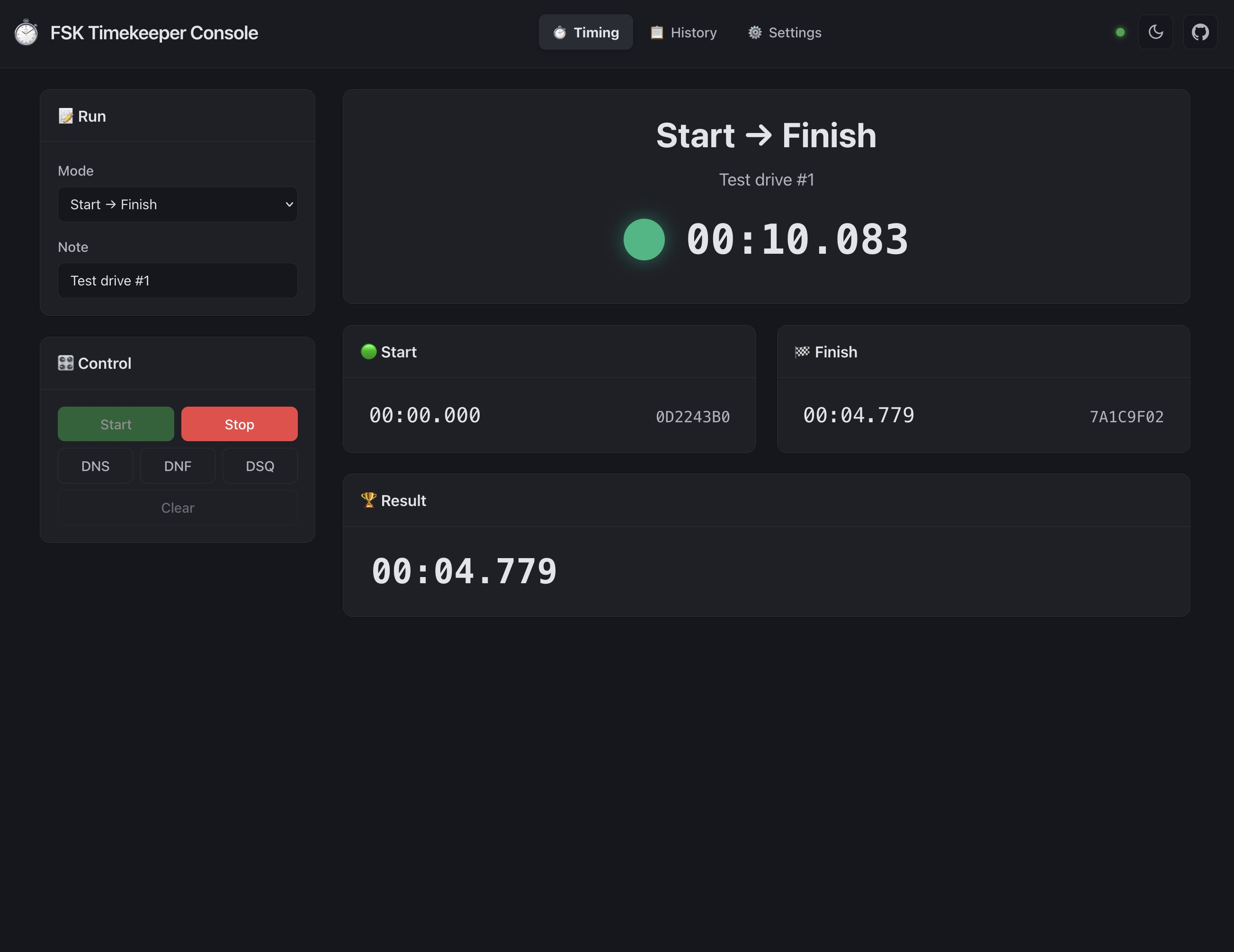
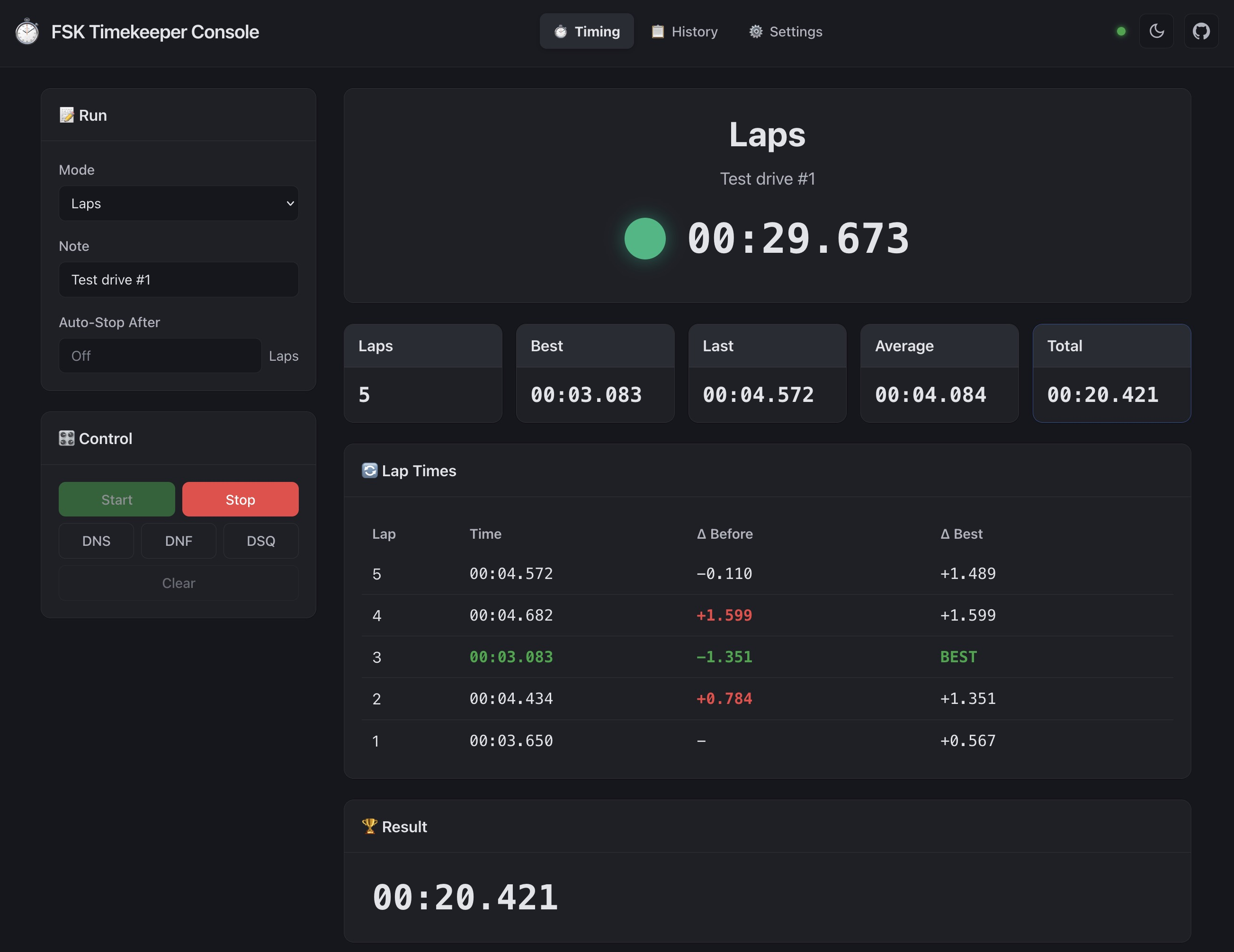
Start sensor.Start → Finish or Laps in Timing.Start to arm the timer. Timing starts on the first pass by the start sensor.Start → Finish: pass the finish sensor to end the run.Laps: each subsequent pass by the start sensor records a lap.| Start → Finish | Laps |
|---|---|
 |  |
Results are saved in the browser and listed in History.
Export Excel: export results for the selected mode.Backup → Download: back up results from all modes and device logs as JSON.Backup → Restore: import a JSON backup.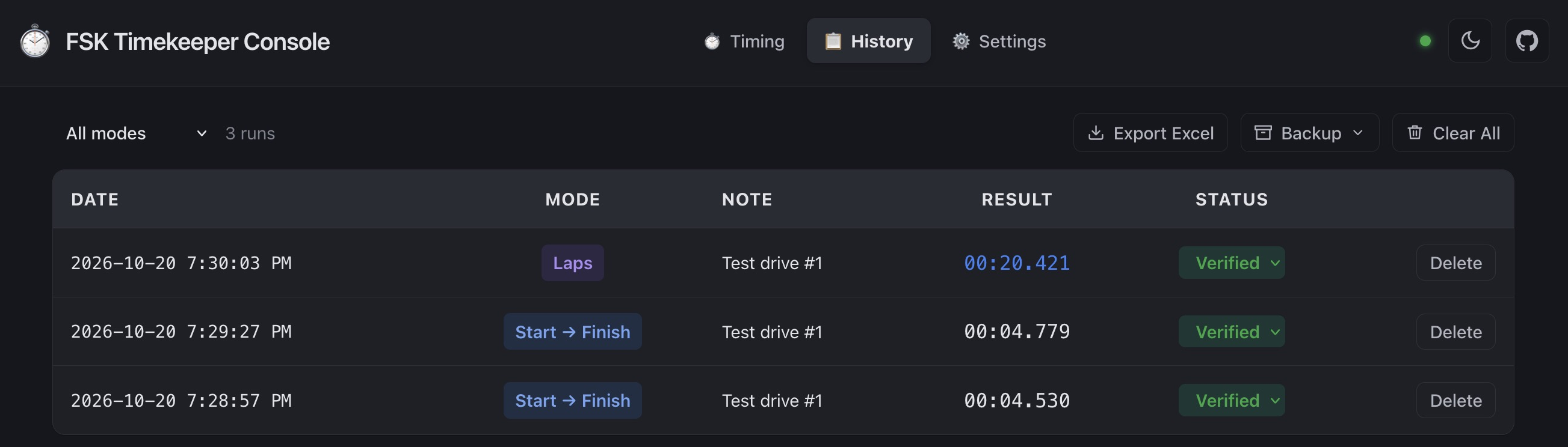
[!IMPORTANT] If a storage error appears, download a backup before closing the page.
Adding the site to your bookmarks may resolve the error.
fsk-timekeeper-pcb.zip from the latest release and extract it.| Qty | Part | Image |
|---|---|---|
| 5x | Assembled fsk-timekeeper PCB | |
| 5x | 22 µH SMD power inductor, 0630 package | 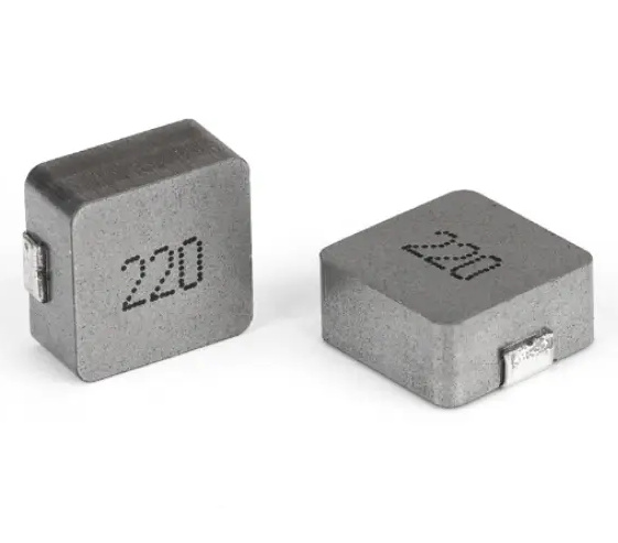 |
| 5x | SuperMini nRF52840 development board | 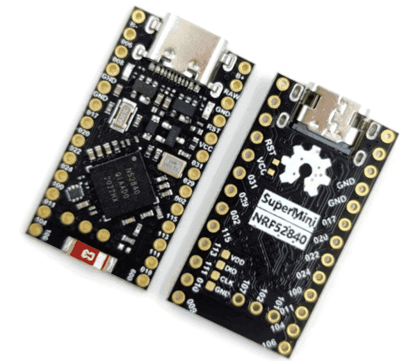 |
| 5x | Ra-01SH LoRa module | 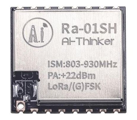 |
| 5x | LoRa antenna with IPEX-to-SMA female cable | 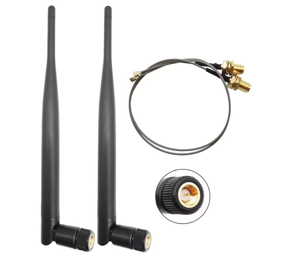 |
| 4x | Single-cell SMD 18650 battery holder and 18650 battery | 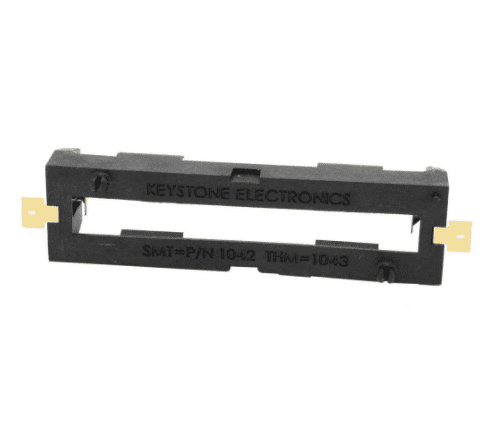 |
| 4x | MTS-102 mini toggle switch | 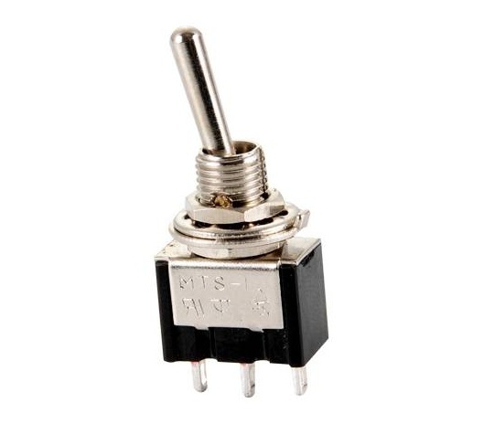 |
| 4x | Autonics BA2M-DDT diffuse reflective photoelectric sensor | 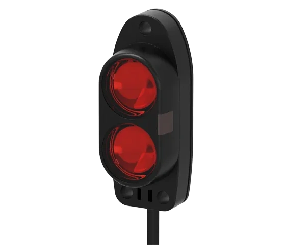 |
| 4x | Molex 5569-04A2 (39300040) board connector | 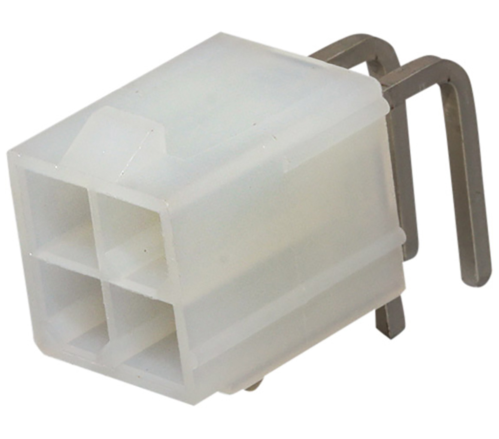 |
| 4x | Molex 5557-04R (39012040) cable housing | 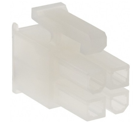 |
| 12x | Molex 5556T (39000038) crimp terminal | 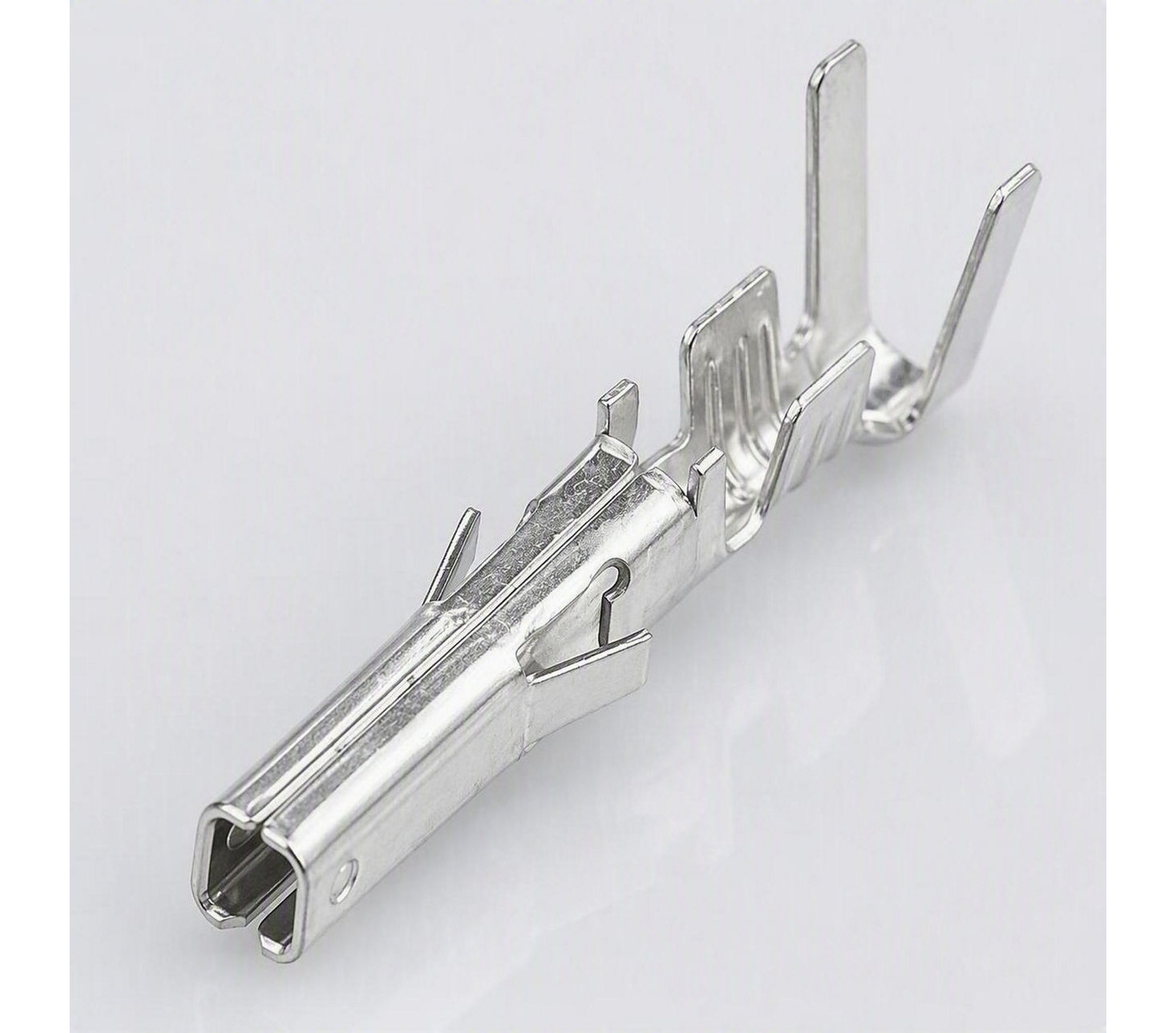 |
| 1x | ATGM336H GPS module with antenna (optional) | 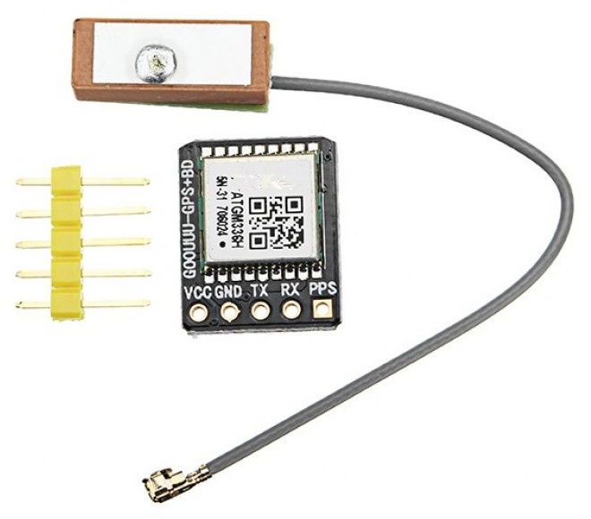 |
[!NOTE] The JLCPCB PCBA order above costs about $7, excluding shipping.
The full set of parts costs about $40 on AliExpress, excluding BA2M-DDT sensors and 18650 batteries.
[!IMPORTANT] Solder
U2first. InstallingU1first makesU2harder to solder.
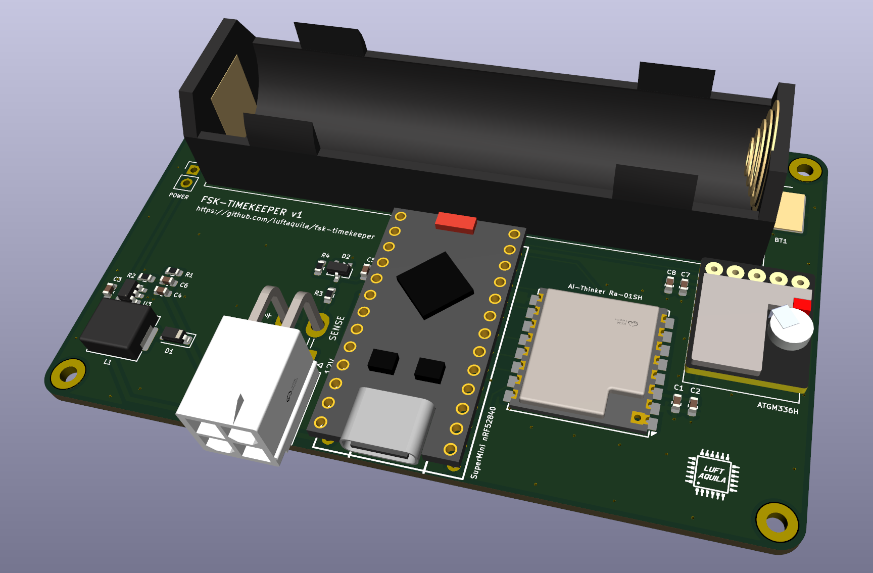
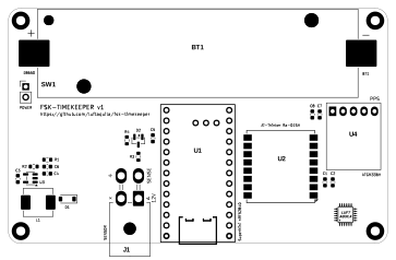
U2 (Ra-01SH), U1 (SuperMini nRF52840), and L1 (22 µH 0630 inductor).U4 and connect its antenna.BT1 and the 5569-04A2 connector at J1, then wire the toggle switch to SW1.| 3D view | Layout |
|---|---|
 |  |
Required per sensor: 4x M2 × 8 mm and 3x M3 × 14 mm hex bolts.
fsk-timekeeper-3d.zip from the latest release and extract it.master.stl, 4x sensor.stl, and 4x sensor-holder.stl.BA2M-DDT sensor to the holder with M3 bolts, then mount the holder on a tripod.Firmware Upgrade, select fsk-timekeeper-firmware.zip and click Upgrade.RST pin to GND twice quickly.Reconnect and select the board to verify the new firmware version.Radio Key and apply it to the first board.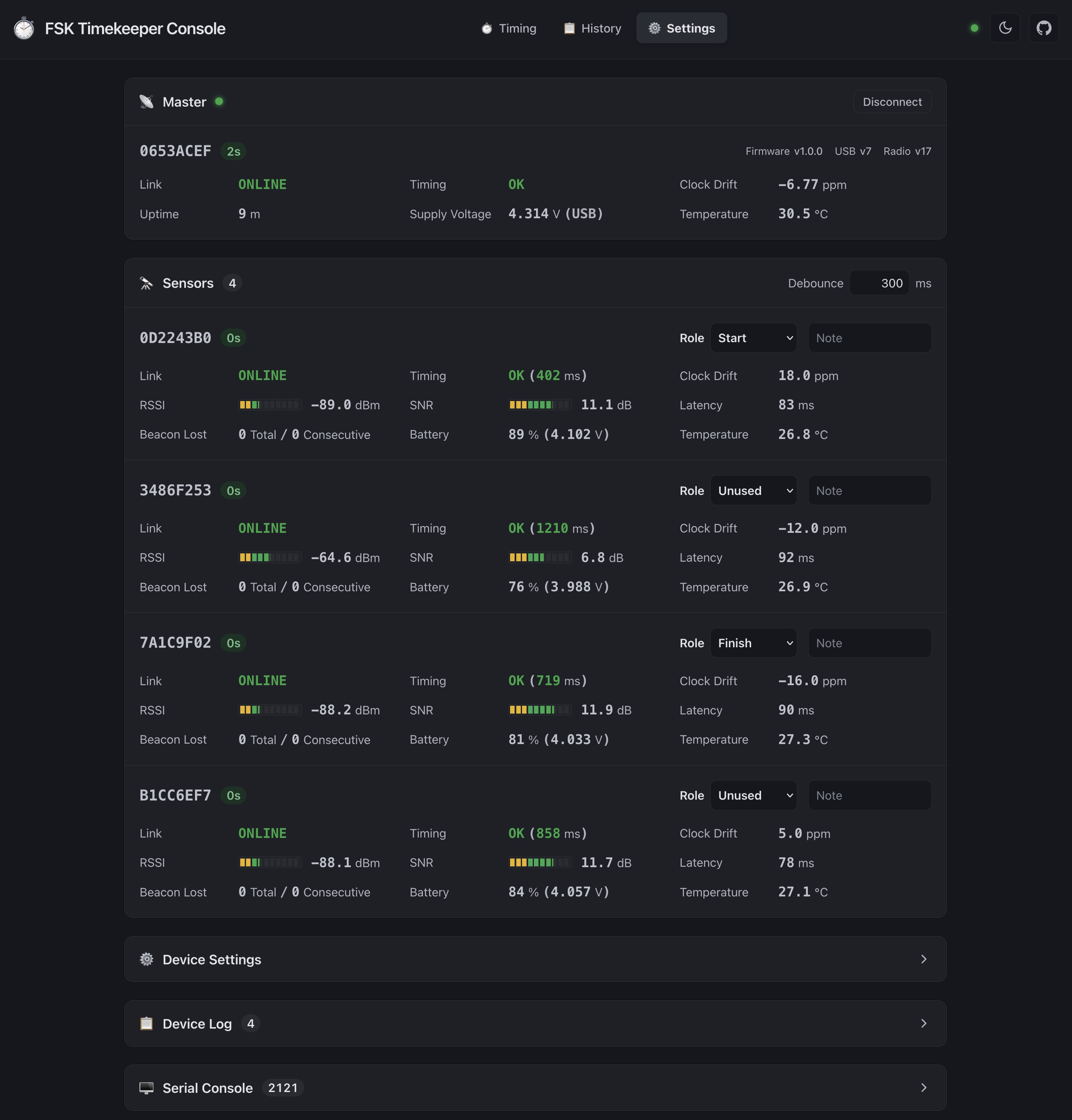
[!IMPORTANT] The master and all sensors must use the same firmware version, radio settings, and key.
[!TIP] The board connected over USB acts as the master. Battery-powered boards act as sensors.
| Pinout | Wiring |
|---|---|
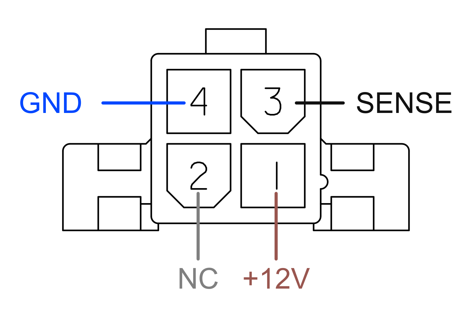 | 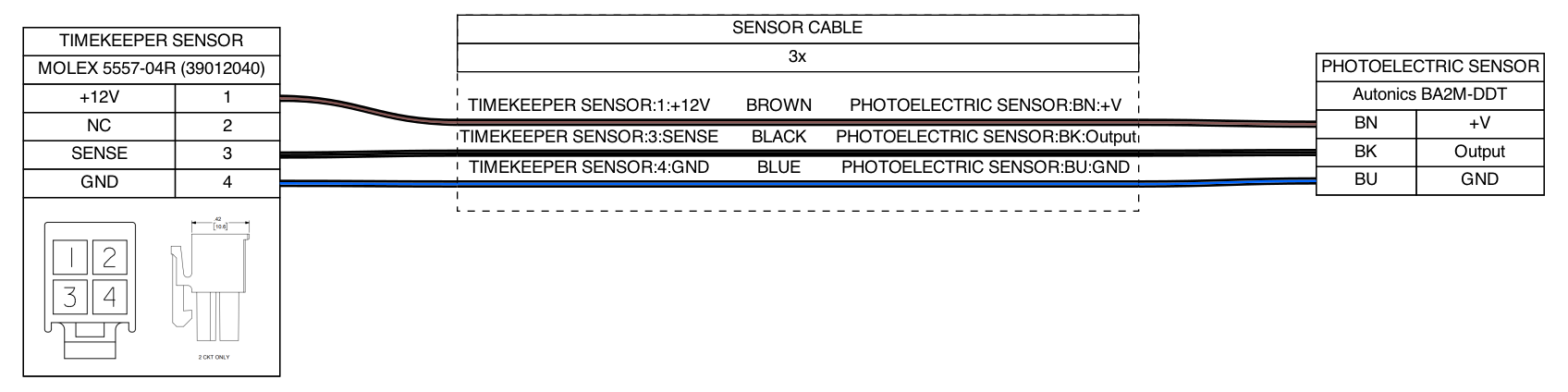 |
Requires: Arm GNU Toolchain (arm-none-eabi-gcc, newlib-nano), Make, Python 3
make -C device/firmware test
make -C device/firmwareRequires: Node.js 22
cd console
npm ci
npm test
npm run dev           # development server
npm run build:single # standalone HTML at dist-single/index.htmlRequires: OpenSCAD Nightly
make -C device/3dFor non-commercial use only:
"THE BEERWARE LICENSE" (Revision 42):
LUFT-AQUILA wrote this project. As long as you retain this notice,
you can do whatever you want with this stuff. If we meet someday,
and you think this stuff is worth it, you can buy me a beer in return.
이 저장소의 모든 내용은 비상업적 용도로 자유롭게 사용할 수 있습니다.
이 프로젝트가 마음에 든다면, 언젠가 우리가 만나게 되었을 때 맥주 한 잔 사 주세요.
| Qty | Value | Footprint | References |
|---|---|---|---|
| 4 | 10uF | Capacitor_SMD:C_0603_1608Metric | C2, C3, C4, C8 |
| 2 | 100nF | Capacitor_SMD:C_0603_1608Metric | C1, C7 |
| 1 | 100pF | Capacitor_SMD:C_0603_1608Metric | C5 |
| 1 | 110k | Resistor_SMD:R_0603_1608Metric | R2 |
| 1 | 18650 | Battery:BatteryHolder_Keystone_1042_1x18650 | BT1 |
| 1 | 1M | Resistor_SMD:R_0603_1608Metric | R1 |
| 1 | 22uH | Inductor_SMD:L_Sunlord_MWSA0603S | L1 |
| 1 | 330 | Resistor_SMD:R_0603_1608Metric | R3 |
| 1 | 4.7k | Resistor_SMD:R_0603_1608Metric | R4 |
| 1 | 47pF | Capacitor_SMD:C_0603_1608Metric | C6 |
| 1 | ATGM336H | lib:ATGM336H_GPS_Module | U4 |
| 1 | Ai-Thinker Ra-01SH | RF_Module:Ai-Thinker-Ra-01-LoRa | U2 |
| 1 | B5819W | Diode_SMD:D_SOD-123 | D1 |
| 1 | BAT54S | Package_TO_SOT_SMD:SOT-23 | D2 |
| 1 | LOGO | lib:luftaquila | G*** |
| 1 | POWER | Connector_PinHeader_2.54mm:PinHeader_1x02_P2.54mm_Vertical | SW1 |
| 1 | SENSOR | Connector_Molex:Molex_Mini-Fit_Jr_5569-04A2_2x02_P4.20mm_Horizontal | J1 |
| 1 | SuperMini nRF52840 | lib:SuperMini_NRF52840 | U1 |
| 1 | TPS61040DBV | Package_TO_SOT_SMD:SOT-23-5 | U3 |
The 23 most common of 27 parts.

Novin3dp/7inch-hdmi-screen
این برد دولایه (۶۸×۴۲ میلیمتر) همان پنل ۷ اینچ AT070TN92 و تاچ GT915 را این بار از پورت DSI رزبریپای راه میاندازد. نسخهی HDMI در پوشهی hardware/ دستنخورده باقی مانده است.


STB1019/BLINDO2.0
Blindo is an open source project made by the members of IEEE Student Branch 1019 from Brescia University (Università degli Studi di Brescia) in collaboration with the organization (Informatici Senza…


hatlabs/HALMET-hardware
Hat Labs Marine Engine & Tank interface hardware design files


It measures 92 × 57 mm and has 2 copper layers, 1.6 mm thick.
27 parts, built around the TPS61040DBV, B5819W and BAT54S. The full list of its parts is on this page, with links to each part's symbol and footprint where PCBKit's library has them.
From the luftaquila/fsk-timekeeper repository on GitHub, at the commit this page was made from: the board is device/hardware/fsk-timekeeper.kicad_pcb and its schematic device/hardware/fsk-timekeeper.kicad_sch. PCBKit opens the board in the browser, with nothing to install.
Its repository states no licence, so its author keeps all rights: ask luftaquila before reusing the design.