4 layers113.1 × 57 mm

 lucblender/lx-deciim5
lx-deciim is a dual-channel bitcrusher Eurorack module based on the Daisy Seed. Unlike traditional bitcrushers, it lets you selectively disable bits and replace them with CV-controlled triggers. Features include 12-bit audio, downsampling, and flexible control over audio shaping and degradation.
Lx deciim is an open-source printed circuit board by lucblender, from the lucblender/lx-deciim repository on GitHub. It is a 2-layer board of 119.9 × 108 mm with 206 parts on 159 nets, routed with 852 tracks and 106 vias.
It is built around the MCP6004-E/P, AZ1117CH2-5.0TRG1 and US1B. Its parts include 68 resistors, 29 connectors, 21 capacitors, 14 diodes and 12 switches. It belongs with the audio and music boards of this library.


The lx-deciim is a unique 2-channel bitcrusher eurorack module. Conventionals bitcrushers reduce resolution of the input bit by bit starting by the LSB (Least Significant Bit).
The lx-deciim let you select which bit you want to disable. In addition, when a bit is disabled, it can be replaced by a CV input going through a trigger to get a clean '0' '1' value.
The trigger compares the input value against the CV to a reference voltate. This ref value can be set to either 0V or 2.5V from a jumper on the back of the module. In addition, you can also downsample the input signal.
The module is based on the Daisy Seed by Electrosmith.
The concept of the module can be described by the following equation:
audioOut = (audioIn & ~concatSwitch) + (concatTrigger & concatSwitch)
Considering:
audioOut : 12 bits binary audio output in (integer)audioIn : 12 bits binary audio input in (integer)concatSwitch : 12 bits binary value of the concatenation of the switches' valueconcatTrigger : 12 bits binary value of the concatenation of the input trigger value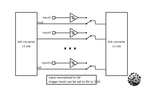
The module consist of 2 PCBs. The main PCB (in reality two PCBs on a panel), and the front panel. The main PCB is really standard 2 layers PCB. After snapping the panel, you can assemble the two PCBs together with the help of male/female header. The front panel is a one layer PCB. I chose matte black solder mask, white silkscreen and ENIG finish on the copper.
All PCB shown in pictures in this repo are manufactured using PCBWay services.
PCBWay provides high-quality PCB manufacturing with reliable service and fast turnaround times, making them my first choice for prototyping as seen in this project. They can also make more complex PCB to fit any of your requirements.
This project is licensed under the CC BY-NC 4.0 License. You may use, modify, and share it for non-commercial purposes.
| Qty | Value | Footprint | References |
|---|---|---|---|
| 50 | , , , , , , , , , , , , , , , +34 | ||
| 26 | 1k | Resistor_SMD:R_0603_1608Metric | R2, R10, R12, R14, R17, R18, R20, R22, R24, R27, R28, R31, R32, R35, R36, R39 +10 |
| 24 | 100k | Resistor_SMD:R_0603_1608Metric | R1, R5, R11, R15, R16, R23, R25, R29, R33, R37, R41, R47, R51, R52, R53, R56 +8 |
| 16 | AudioJack2_SwitchT | PJ301M-12:PJ301M-12 | J1, J2, J3, J4, J5, J6, J7, J8, J9, J10, J11, J12, J13, J14, J15, J16 |
| 12 | 1Meg | Resistor_SMD:R_0603_1608Metric | R3, R9, R13, R19, R21, R26, R30, R34, R38, R42, R45, R49 |
| 12 | 2MS1T1B3M2QES | 2MS1T1B3M2QES:2MS1T1B3M2QES | S1, S2, S3, S4, S5, S6, S7, S8, S9, S10, S11, S12 |
| 12 | LED | LED_THT:LED_D3.0mm | D1, D2, D3, D4, D5, D6, D7, D8, D9, D10, D11, D12 |
| 10 | 100n | Capacitor_SMD:C_0603_1608Metric | C1, C2, C3, C6, C7, C12, C15, C17, C19, C21 |
| 6 | 47p | Capacitor_SMD:C_0603_1608Metric | C4, C5, C8, C9, C10, C13 |
| 4 | 33k | Resistor_SMD:R_0603_1608Metric | R54, R59, R61, R66 |
| 4 | MCP6004 | Package_SO:SOIC-14_3.9x8.7mm_P1.27mm | U1, U3, U4, U6 |
| 3 | 10u | Capacitor_SMD:C_0603_1608Metric | C11, C14, C18 |
| 3 | Conn_01x03_Pin | Connector_PinHeader_2.54mm:PinHeader_1x03_P2.54mm_Vertical | J24, J26, J28 |
| 3 | Conn_01x03_Socket | Connector_PinSocket_2.54mm:PinSocket_1x03_P2.54mm_Vertical | J25, J27, J29 |
| 2 | 1u | Capacitor_SMD:C_0603_1608Metric | C16, C20 |
| 2 | 2Meg | Resistor_SMD:R_0603_1608Metric | R64, R68 |
| 2 | Conn_01x15_Pin | Connector_PinHeader_2.54mm:PinHeader_1x15_P2.54mm_Vertical | J18, J20 |
| 2 | Conn_01x15_Socket | Connector_PinSocket_2.54mm:PinSocket_1x15_P2.54mm_Vertical | J19, J21 |
| 2 | FerriteBead | Inductor_SMD:L_0805_2012Metric | FB1, FB2 |
| 2 | US1B | Diode_SMD:D_SMA | D13, D14 |
| 1 | 10k | Potentiometer_THT:Potentiometer_Alpha_RD901F-40-00D_Single_Vertical | RV1 |
| 1 | AZ1117CH2-5.0TRG1 | AZ1117CH2-5.0TRG1:SOT230P700X180-4N | IC1 |
| 1 | Conn_01x10 | Connector_PinHeader_2.54mm:PinHeader_2x05_P2.54mm_Vertical_SMD | J17 |
| 1 | Conn_01x12_Pin | Connector_PinHeader_2.54mm:PinHeader_1x12_P2.54mm_Vertical | J22 |
| 1 | Conn_01x12_Socket | Connector_PinSocket_2.54mm:PinSocket_1x12_P2.54mm_Vertical | J23 |
| 1 | Electrosmith_Daisy_Seed_Rev4 | Module:Electrosmith_Daisy_Seed | A1 |
| 1 | Jumper_3_Open | Connector_PinHeader_2.54mm:PinHeader_1x03_P2.54mm_Vertical | JP1 |
| 1 | MCP6001-OT | Package_TO_SOT_SMD:SOT-23-5 | U2 |
| 1 | TL074 | TL074:SOP50P326X110-14N | U5 |


lucblender/lx-sw-btn
The "lx-sw-btn": a 2HP eurorack module with 4 customizable switches enabled CV outputs!

lucblender/MIDI-sync-power-dev-board
The MIDI-sync-power-dev-board is a 4hp eurorack module allowing you to get an isolated 5V, 3.3V from LDO, a sync in from 3.5mm jack and either midi input or midi output.


It measures 119.9 × 108 mm and has 2 copper layers, 1.6 mm thick.
206 parts, built around the MCP6004-E/P, AZ1117CH2-5.0TRG1 and US1B. The full list of its parts is on this page, with links to each part's symbol and footprint where PCBKit's library has them.
From the lucblender/lx-deciim repository on GitHub, at the commit this page was made from: the board is Hardware/lx-deciim/lx-deciim.kicad_pcb and its schematic Hardware/lx-deciim/audio_io.kicad_sch. PCBKit opens the board in the browser, with nothing to install.
Its repository states no licence, so its author keeps all rights: ask lucblender before reusing the design.