2 layers52.5 × 30.5 mm

 hmcty/kicad-ws
Collection of personal KiCAD projects
Deloop lite mk0 is an open-source printed circuit board by hmcty, from the hmcty/kicad-ws repository on GitHub, published under the MIT licence. It is a 4-layer board of 178 × 83.3 mm with 99 parts on 95 nets, routed with 641 tracks and 56 vias.
It is built around the TL072, LT1931ES5 and OPA2134UA, with the H11L1 and US1B among its other parts. Its parts include 31 resistors, 29 capacitors, 10 ICs, 9 connectors and 4 diodes. It belongs with the NXP (LPC, Kinetis, i.MX RT) boards of this library.


A breadboard-compatible, split power supply for prototyping audio circuits.
Provides low-noise, stable +/- 7V rails. Expects 9V DC input.
Parts:
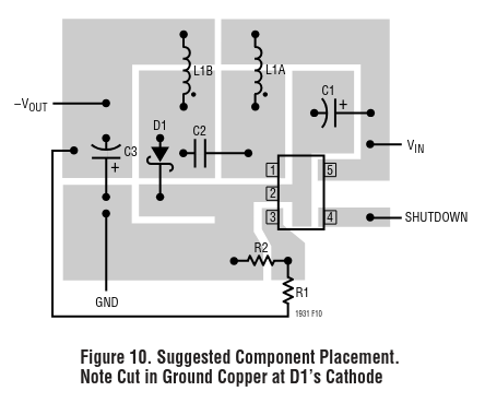
Analog Devices recommends the following layout for the LT1931:
| Qty | Value | Footprint | References |
|---|---|---|---|
| 10 | 100N | Capacitor_SMD:C_0603_1608Metric_Pad1.08x0.95mm_HandSolder | C1, C4, C7, C8, C9, C10, C12, C15, C28, C29 |
| 8 | 10K 0.1% | Resistor_SMD:R_0603_1608Metric_Pad0.98x0.95mm_HandSolder | R20, R21, R22, R23, R24, R25, R26, R31 |
| 6 | MountingHole | MountingHole:MountingHole_3.2mm_M3 | H1, H2, H3, H4, H5, H6 |
| 5 | 47 K | Resistor_SMD:R_0603_1608Metric_Pad0.98x0.95mm_HandSolder | R1, R2, R3, R4, R5 |
| 4 | 100 0.1% | Resistor_SMD:R_0603_1608Metric_Pad0.98x0.95mm_HandSolder | R14, R15, R16, R18 |
| 4 | 10N | Capacitor_SMD:C_0805_2012Metric_Pad1.18x1.45mm_HandSolder | C22, C23, C24, C25 |
| 3 | 1u | Capacitor_SMD:C_1206_3216Metric_Pad1.33x1.80mm_HandSolder | C13, C14, C17 |
| 3 | Jumper_2_Open | Connector_PinHeader_2.54mm:PinHeader_1x02_P2.54mm_Vertical | JP3, JP4, JP5 |
| 3 | TL072 | Package_SO:SOIC-8_3.9x4.9mm_P1.27mm | U3, U4, U5 |
| 2 | 10N | Capacitor_SMD:C_0603_1608Metric_Pad1.08x0.95mm_HandSolder | C2, C3 |
| 2 | 10u | Capacitor_SMD:C_1206_3216Metric_Pad1.33x1.80mm_HandSolder | C20, C21 |
| 2 | 123K 0.1% | Resistor_SMD:R_0603_1608Metric_Pad0.98x0.95mm_HandSolder | R33, R35 |
| 2 | 150N C0G | Capacitor_SMD:C_1812_4532Metric_Pad1.57x3.40mm_HandSolder | C5, C6 |
| 2 | 15K 0.1% | Resistor_SMD:R_0603_1608Metric_Pad0.98x0.95mm_HandSolder | R17, R19 |
| 2 | 15u | Inductor_SMD:L_1812_4532Metric_Pad1.30x3.40mm_HandSolder | L1, L2 |
| 2 | 1M | Resistor_SMD:R_0603_1608Metric_Pad0.98x0.95mm_HandSolder | R6, R7 |
| 2 | 2.2u | Capacitor_SMD:C_0805_2012Metric_Pad1.18x1.45mm_HandSolder | C26, C27 |
| 2 | 47R 0.1% | Resistor_SMD:R_0603_1608Metric_Pad0.98x0.95mm_HandSolder | R12, R13 |
| 2 | 604K 0.1% | Resistor_SMD:R_0603_1608Metric_Pad0.98x0.95mm_HandSolder | R32, R34 |
| 2 | AudioJack3_Switch | custom:Jack_6.35mm_Neutrik_NMJ6HCD2_Horizontal | J4, J5 |
| 2 | Jumper_2_Bridged | Connector_PinHeader_2.54mm:PinHeader_1x02_P2.54mm_Vertical | JP1, JP2 |
| 2 | NetTie_2 | NetTie:NetTie-2_SMD_Pad2.0mm | NT1, NT2 |
| 1 | 10u | Capacitor_THT:CP_Radial_D5.0mm_P2.00mm | C11 |
| 1 | 1K4 | Resistor_SMD:R_0603_1608Metric_Pad0.98x0.95mm_HandSolder | R27 |
| 1 | 1N4148 | Diode_SMD:Nexperia_CFP3_SOD-123W | D7 |
| 1 | 220R | Resistor_SMD:R_0603_1608Metric_Pad0.98x0.95mm_HandSolder | R28 |
| 1 | 220p | Capacitor_SMD:C_0805_2012Metric_Pad1.18x1.45mm_HandSolder | C18 |
| 1 | 22u | Capacitor_SMD:C_0805_2012Metric_Pad1.18x1.45mm_HandSolder | C19 |
| 1 | 270R | Resistor_SMD:R_0603_1608Metric_Pad0.98x0.95mm_HandSolder | R29 |
| 1 | 4.7u | Capacitor_SMD:C_0805_2012Metric_Pad1.18x1.45mm_HandSolder | C16 |
| 1 | 60K 0.1% | Resistor_SMD:R_0603_1608Metric_Pad0.98x0.95mm_HandSolder | R30 |
| 1 | AudioJack3 | custom:Jack_3.5mm_CUI_SJ1-3523N_Horizontal | J8 |
| 1 | Barrel_Jack_Switch | Connector_BarrelJack:BarrelJack_Horizontal | J6 |
| 1 | Conn_01x02_Pin | Connector_PinHeader_2.54mm:PinHeader_1x02_P2.54mm_Vertical | J1 |
| 1 | Conn_01x02_Socket | Connector_Wire:SolderWire-1.5sqmm_1x02_P7.8mm_D1.7mm_OD3.9mm | J7 |
| 1 | Conn_01x08_Socket | Connector_JST:JST_XH_B8B-XH-AM_1x08_P2.50mm_Vertical | J10 |
| 1 | Conn_02x20_Odd_Even | Connector_IDC:IDC-Header_2x20_P2.54mm_Vertical | J9 |
| 1 | D_Schottky | Capacitor_SMD:C_1206_3216Metric_Pad1.33x1.80mm_HandSolder | D8 |
| 1 | H11L1 | Package_DIP:SMDIP-6_W9.53mm | U7 |
| 1 | LED | LED_SMD:LED_1206_3216Metric_Pad1.42x1.75mm_HandSolder | D6 |
| 1 | LT1931 | Package_TO_SOT_SMD:TSOT-23-5_HandSoldering | U8 |
| 1 | Micro_SD_Card_Det2 | Connector_Card:microSD_HC_Hirose_DM3AT-SF-PEJM5 | J3 |
| 1 | OPA2134 | Package_SO:SOIC-8_3.9x4.9mm_P1.27mm | U2 |
| 1 | TPS7A30 | Package_SO:MSOP-8-1EP_3x3mm_P0.65mm_EP1.68x1.88mm_ThermalVias | U10 |
| 1 | TPS7A49 | Package_SO:MSOP-8-1EP_3x3mm_P0.65mm_EP1.68x1.88mm_ThermalVias | U9 |
| 1 | TestPoint | TestPoint:TestPoint_Pad_4.0x4.0mm | TP1 |
| 1 | US1B | Diode_SMD:D_SMA | D5 |
| 1 | uA7805 | Package_TO_SOT_SMD:TO-263-2 | U6 |
| 1 | ~ | Module:Electrosmith_Daisy_Seed | U1 |


DADDesign-Projects/PENDA-Hardware
This repository contains the schematics and PCB layouts created with KiCad 8.0 for a versatile digital effects platform that utilizes the Daisy-Seed board from ElectroSmith.

bkshepherd/DaisySeedProjects
A collection of hardware and software projects based around the Electro-Smith Daisy Seed


lucblender/lx-deciim
lx-deciim is a dual-channel bitcrusher Eurorack module based on the Daisy Seed. Unlike traditional bitcrushers, it lets you selectively disable bits and replace them with CV-controlled triggers.

lucblender/lx-sw-btn
The "lx-sw-btn": a 2HP eurorack module with 4 customizable switches enabled CV outputs!

lucblender/MIDI-sync-power-dev-board
The MIDI-sync-power-dev-board is a 4hp eurorack module allowing you to get an isolated 5V, 3.3V from LDO, a sync in from 3.5mm jack and either midi input or midi output.

It measures 178 × 83.3 mm and has 4 copper layers, 1.6 mm thick.
99 parts, built around the TL072, LT1931ES5, OPA2134UA and H11L1. The full list of its parts is on this page, with links to each part's symbol and footprint where PCBKit's library has them.
From the hmcty/kicad-ws repository on GitHub, at the commit this page was made from: the board is boards/deloop_lite_mk0/deloop_lite_mk0.kicad_pcb and its schematic boards/deloop_lite_mk0/audio_buffer.kicad_sch. PCBKit opens the board in the browser, with nothing to install.
Its repository publishes it under the MIT licence: you may reuse it on that licence's terms (keep the author's notice, and for a copyleft licence share your changes alike).