2 layers27 × 23.5 mm
Power Delivery
louisquantran/Micromouse
PCB design for a Micromouse: a small autonomous robot that maps and solves a maze.
5 parts

 louisquantran/Micromouse
PCB design for a Micromouse: a small autonomous robot that maps and solves a maze.
Micromouse Mainboard is an open-source printed circuit board by louisquantran, from the louisquantran/Micromouse repository on GitHub. It is a 2-layer board of 75 × 87 mm with 75 parts on 83 nets, routed with 621 tracks and 1,674 vias.
It is built around the L293DD, INL-5AMIR15 and EG1218. Its parts include 25 capacitors, 22 resistors, 8 diodes, 7 ICs and 5 connectors. It belongs with the computers and single-board computers boards and the STM32 boards of this library.


PCB design for a Micromouse: a small autonomous robot that maps and solves a maze.
The board is designed in KiCad and built around an STM32F205 microcontroller, with two DC motors with encoders driven by an L293DD H-bridge and IR emitter/phototransistor pairs for wall sensing.
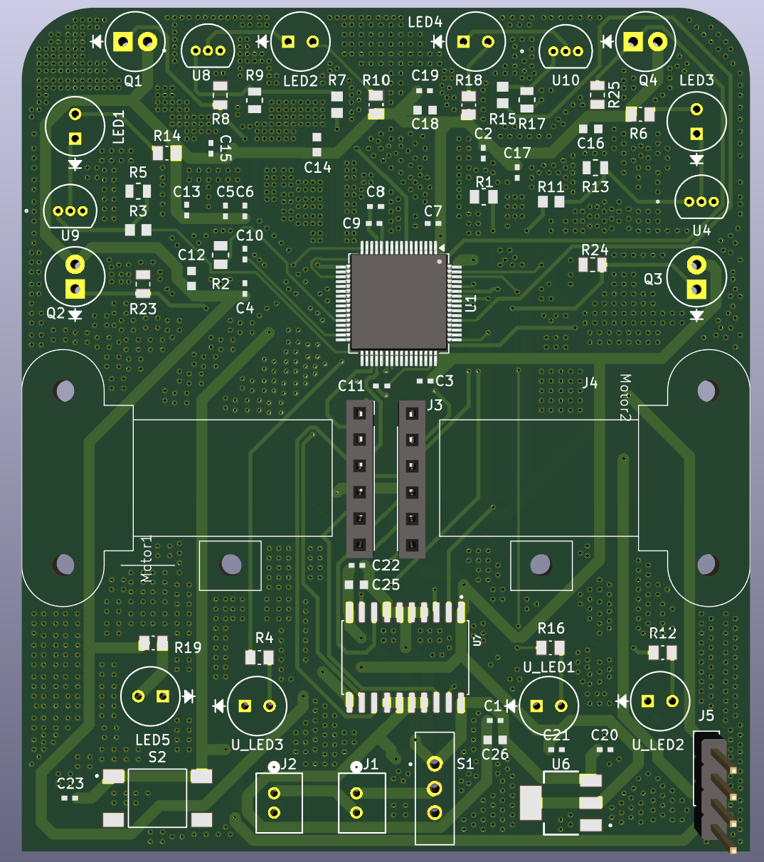
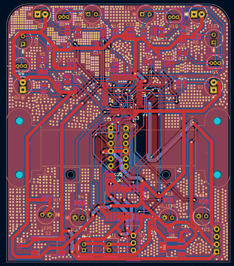
Left: 3D render. Right: copper layout (red = front, blue = back).
2-layer board with copper pours on both sides, the STM32 in the center, IR emitter/receiver pairs around the front edge for wall sensing, motor mounts on both sides and the H-bridge, voltage regulator and power switch along the back.
Micromouse/
├── docs/                         # PCB images
├── mouse/                        # Main robot board
│   ├── Micromouse_Mainboard/     # Full schematic + PCB (open this one)
│   ├── IR_Emitter+IR_Receiver/   # IR sensing sub-circuit
│   └── Power_Delivery+H_Bridge/  # Power + motor driver sub-circuit
└── rat/                          # Individual sub-circuit projects
    ├── IR_Emitter/
    ├── IR_Receiver/
    ├── Motor_Control(H-Bridge)/
└── Power_Delivery/| Function | Part |
|---|---|
| Microcontroller | STM32F205RGT6 |
| Motor driver | L293DD dual H-bridge |
| 3.3 V regulator | AZ1117IH-3.3 |
| IR emitters | INL-5AMIR15, switched by BS170 N-MOSFETs |
| IR receivers | SFH 313 FA-3/4 phototransistors |
| Power switch | EG1218 slide switch |
| Motor / battery connectors | JST PH (B2B-PH-K-S) |
| Passives | 0805 resistors and capacitors |
| Qty | Value | Footprint | References |
|---|---|---|---|
| 13 | 0.1uF | 0.1uF_Capacitor:CAP_CL05_SAM | C2, C3, C4, C6, C7, C8, C9, C13, C15, C17, C19, C22, C23 |
| 6 | 4.7uF | 4.7uF_Capacitor:CAP_0603_CL10A_1P6XP8_SAM | C12, C14, C16, C18, C25, C26 |
| 4 | 1.8k Ohm | 1.8kohms_Resistor:RESC2012X60N | R8, R23, R24, R25 |
| 4 | 100 Ohm | 100ohms_Resistor:RC0805N_YAG | R3, R7, R11, R15 |
| 4 | 43Ohms | 43ohms_Resistor:RESC2012X60N | R4, R12, R16, R19 |
| 4 | 47k Ohm | 47kohms_Resistor:STA_RMCF0805_STP | R5, R9, R13, R17 |
| 4 | 51 Ohm | 51ohms_Resistor:RESC2012X60N | R6, R10, R14, R18 |
| 4 | INL-5AMIR15 | IR_Emitter:LED_INL-5AMIR15_INO | LED5, U_LED1, U_LED2, U_LED3 |
| 4 | IR Receiver | Phototransistor:SFH 313 FA-3&slash_4_OSR | Q1, Q2, Q3, Q4 |
| 4 | IR_Emitter | IR_Emitter:LED_INL-5AMIR15_INO | LED1, LED2, LED3, LED4 |
| 4 | MOSFET | N_MOSFET:TO_SA06_ONS | U4, U8, U9, U10 |
| 3 | 10uF | 0.1uF_Capacitor:CAP_CL05_SAM | C1, C5, C20 |
| 2 | 10kOhms | 10kohms_Resistor:BO_CR0805 | R1, R2 |
| 2 | 2.2uF | 0.1uF_Capacitor:CAP_CL05_SAM | C10, C11 |
| 2 | ~ | Motor_Pololu:Pololu_Motor | Motor1, Motor2 |
| 1 | 22uF | 0.1uF_Capacitor:CAP_CL05_SAM | C21 |
| 1 | Button | Button:SW_4-1437565-1 | S2 |
| 1 | EG1218 | Switch_EG1218:SW_EG1218 | S1 |
| 1 | JST 1 | B2B-PH-K-S:CONN2_B2B-PH-K-S_JST | J1 |
| 1 | JST 2 | B2B-PH-K-S:CONN2_B2B-PH-K-S_JST | J2 |
| 1 | L293DD | L293DD:SOIC127P1032X265-20N | U7 |
| 1 | Left Header | Connector_PinSocket_2.54mm:PinSocket_1x06_P2.54mm_Vertical | J3 |
| 1 | PinHeader_1x04_P2.54mm_Vertical | Connector_PinHeader_2.54mm:PinHeader_1x04_P2.54mm_Vertical | J5 |
| 1 | Right Header | Connector_PinSocket_2.54mm:PinSocket_1x06_P2.54mm_Vertical | J4 |
| 1 | STM32F205RGTx | Package_QFP:LQFP-64_10x10mm_P0.5mm | U1 |
| 1 | Voltage Regulator | Voltage_Regulator_AZ1117IH-3.3TRG1:SOT230P700X185-4N | U6 |
louisquantran/Micromouse
PCB design for a Micromouse: a small autonomous robot that maps and solves a maze.


silveirago/Faduino
The Faduino is a DIY MIDI controller inspired in the Presonus Faderport. It has one motorized fader, a rotary encoder and several silicone buttons, plus two PCBs.


almirpangor/VIHR-30-EFI
Блок управления впрыском и зажиганием для лодочного мотора «Вихрь-30»


It measures 75 × 87 mm and has 2 copper layers, 1.6 mm thick.
75 parts, built around the L293DD, INL-5AMIR15 and EG1218. The full list of its parts is on this page, with links to each part's symbol and footprint where PCBKit's library has them.
From the louisquantran/Micromouse repository on GitHub, at the commit this page was made from: the board is mouse/Micromouse_Mainboard/Micromouse_Mainboard.kicad_pcb and its schematic mouse/IR_Emitter+IR_Receiver/IR_Emitter.kicad_sch. PCBKit opens the board in the browser, with nothing to install.
Its repository states no licence, so its author keeps all rights: ask louisquantran before reusing the design.