4 layers140.3 × 129 mm
Pec
Raduas/STM32-furnace
Home project to create H-bridge resonant induction furnace
128 partsApache-2.0

 Loic74650/ioBoard3
A relay (and more!) board with Ethernet connectivity and MQTT support
IoBoard is an open-source printed circuit board by Loic74650, from the Loic74650/ioBoard repository on GitHub, published under the GPL-3.0 licence. It is a 4-layer board of 70 × 143 mm with 206 parts on 247 nets, routed with 1,148 tracks and 240 vias.
It is built around the 74AHC1G125GW, AP1509-SG and FT232RL, with the LM2904, SFH617A-1 and DS1307+ among its other parts. Its parts include 67 resistors, 36 capacitors, 29 diodes, 26 connectors and 22 ICs. It belongs with the home automation and IoT and interfaces and adapters boards and the AVR (ATmega, ATtiny) boards of this library.


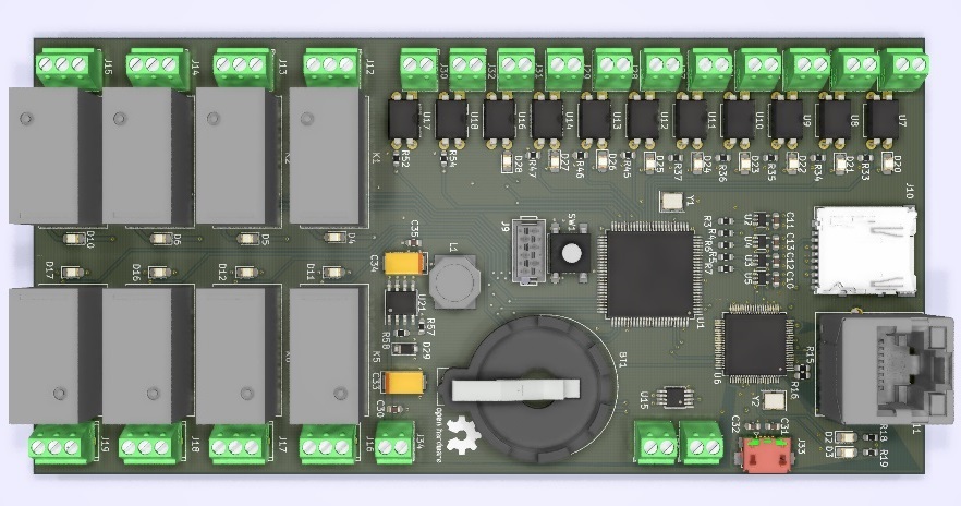
Simply put, ioBoard is a mix between an Arduino Mega board, the Ethernet shield and the relay shield + some small additional features (RTC, opto-isolation of digital inputs/outputs, two analog inputs, one Teleinfo input…).
It supports the MQTT protocol and has a set of API functions so that it is easy to control it over the Ethernet for home automation applications for instance.
ioBoard can be programmed to perform tasks at regular intervals such as water the garden or switch on a pump autonomously.
ioBoard also has input pulse counters, typically used to track the consumption of a gas or oil heater, water or even electrical consumption.
ioBoard also has a TeleInfo input, which is a French dedicated energy meter interface to the main electric meter of the house.
Finally, ioBoard has a small web server stored on an SD card, in order to reflect the status of the board I/Os.
Before compiling the code and flashing it onto the µC, make sure you have changed the following variables in the code:
Below are the Payloads/commands to publish on the "ioBoard/API" topic in Json format in order to launch actions on the ioBoard:
The status of the I/Os is published on the "ioBoard/IOs" topic in the following Json format:
The above Json commands representing the state of the I/Os are updated as soon as a Digital I/O changes state or every 30 secs for the Analog Inputs.
| Qty | Value | Footprint | References |
|---|---|---|---|
| 19 | LED | LED_SMD:LED_0805_2012Metric_Castellated | D2, D3, D10, D11, D12, D16, D17, D20, D21, D22, D23, D24, D25, D26, D27, D28 +3 |
| 18 | 10K | Resistor_SMD:R_0603_1608Metric | R1, R14, R38, R39, R40, R41, R51, R53, R55, R56, R57, R58, R62, R63, R64, R65 +2 |
| 15 | 100nF | Capacitor_SMD:C_0603_1608Metric | C2, C5, C6, C7, C8, C9, C14, C15, C20, C21, C22, C27, C30, C35, C36 |
| 13 | MPT 0.5/3-2.54 | pbo_footprint:TerminalBlock_Phoenix_MPT-0,5-2-2.54_1x02_P2.54mm_Horizontal | J21, J22, J23, J24, J25, J26, J27, J28, J29, J30, J31, J32, J34 |
| 10 | 520 | Resistor_SMD:R_0603_1608Metric | R28, R29, R30, R31, R32, R42, R43, R44, R49, R50 |
| 10 | SFH617A-1 | Package_DIP:DIP-4_W7.62mm | U7, U8, U9, U10, U11, U12, U13, U14, U17, U18 |
| 9 | 1K5 | Resistor_SMD:R_0603_1608Metric | R33, R34, R35, R36, R37, R45, R46, R47, R61 |
| 9 | RU1C001UNTCL | Package_TO_SOT_SMD:SOT-323_SC-70 | Q1, Q2, Q3, Q4, Q5, Q6, Q7, Q8, Q9 |
| 8 | 5K | Resistor_SMD:R_0603_1608Metric | R20, R21, R22, R23, R24, R25, R26, R27 |
| 8 | G5Q-1EU | pbo_footprint:Relay_SPDT_Omron-G5Q-1 | K1, K2, K3, K4, K5, K6, K7, K8 |
| 8 | MPT 0.5/3-2.54 | pbo_footprint:TerminalBlock_Phoenix_MPT-0,5-3-2.54_1x03_P2.54mm_Horizontal | J12, J13, J14, J15, J16, J17, J18, J19 |
| 8 | S1JL R3 | Diode_SMD:D_SMA | D7, D8, D9, D13, D14, D15, D18, D19 |
| 7 | 100 | Resistor_SMD:R_0603_1608Metric | R3, R4, R5, R6, R7, R59, R60 |
| 4 | 10nF | Capacitor_SMD:C_0603_1608Metric | C10, C11, C12, C13 |
| 4 | 1K | Resistor_SMD:R_0603_1608Metric | R8, R9, R18, R19 |
| 4 | 49.9 | Resistor_SMD:R_0603_1608Metric | R10, R11, R12, R13 |
| 4 | 74AHC1G125 | Package_TO_SOT_SMD:SOT-353_SC-70-5 | U2, U3, U4, U5 |
| 3 | 22pF | Capacitor_SMD:C_0603_1608Metric | C1, C23, C24 |
| 2 | 10µF | Capacitor_Tantalum_SMD:CP_EIA-2012-15_AVX-P | C17, C18 |
| 2 | 10µF | Capacitor_Tantalum_SMD:CP_EIA-6032-15_Kemet-U | C33, C34 |
| 2 | 15K | Resistor_SMD:R_0603_1608Metric | R52, R54 |
| 2 | 15pF | Capacitor_SMD:C_0603_1608Metric | C3, C4 |
| 2 | 1M | Resistor_SMD:R_0603_1608Metric | R2, R17 |
| 2 | 1uF | Capacitor_SMD:C_0805_2012Metric | C16, C19 |
| 2 | 1µF | Capacitor_SMD:C_1206_3216Metric | C28, C29 |
| 2 | 1µF | Capacitor_SMD:C_0805_2012Metric | C25, C26 |
| 2 | 47pF | Capacitor_SMD:C_0603_1608Metric | C31, C32 |
| 2 | MH2029-300Y | Inductor_SMD:L_0805_2012Metric | FB2, FB3 |
| 1 | 10µH | Inductor_SMD:L_0805_2012Metric | FB1 |
| 1 | 12K | Resistor_SMD:R_0603_1608Metric | R15 |
| 1 | 16MHz | pbo_footprint:Crystal_SMD_2520-4Pin_2.5x2.0mm | Y1 |
| 1 | 25MHz | Crystal:Crystal_SMD_2016-4Pin_2.0x1.6mm | Y2 |
| 1 | 300 | Resistor_SMD:R_0603_1608Metric | R16 |
| 1 | 32.768KHz | Crystal:Crystal_SMD_3215-2Pin_3.2x1.5mm | Y3 |
| 1 | 4.7K | Resistor_SMD:R_0603_1608Metric | R48 |
| 1 | 47µH | pbo_footprint:L_Bourns-SRU8043 | L1 |
| 1 | 8P8C_LED_Shielded | pbo_footprint:RJ45_Stewart_SS_74301_001 | J11 |
| 1 | AP1509 | Package_SO:SOIC-8_3.9x4.9mm_P1.27mm | U21 |
| 1 | ATmega2560 | Package_QFP:TQFP-100_14x14mm_P0.5mm | U1 |
| 1 | CR2025 | pbo_footprint:BatteryHolder_Keystone_103_1x20mm | BT1 |
| 1 | DS1307+ | Package_SO:SOIC-8_3.9x4.9mm_P1.27mm | U19 |
| 1 | FT232RL | Package_SO:SSOP-28_5.3x10.2mm_P0.65mm | U22 |
| 1 | ICSP | Connector_PinHeader_2.54mm:PinHeader_2x03_P2.54mm_Vertical | J9 |
| 1 | LM2904 | Package_SO:MSOP-8_3x3mm_P0.65mm | U15 |
| 1 | MIC5504-3.3YM5 | Package_TO_SOT_SMD:SOT-23-5 | U20 |
| 1 | MPT 0.5/2-2.54 | pbo_footprint:TerminalBlock_Phoenix_MPT-0,5-2-2.54_1x02_P2.54mm_Horizontal | J20 |
| 1 | Micro_SD_Card | Connector_Card:microSD_HC_Hirose_DM3AT-SF-PEJM5 | J10 |
| 1 | NRVTS2H60ESFT3G | Diode_SMD:D_SOD-123F | D29 |
| 1 | RSFBL-R3 | pbo_footprint:D_Sub_SMA | D1 |
| 1 | SFH620A | Package_DIP:DIP-4_W7.62mm | U16 |
| 1 | SW_DPST | pbo_footprint:SW_SPST_B3S-1000 | SW1 |
| 1 | USB_B_Micro | pbo_footprint:USB_Micro-B_Amphenol_110118192-0001LF_Horizontal | J33 |
| 1 | W5100 | Package_QFP:LQFP-80_10x10mm_P0.4mm | U6 |
It measures 70 × 143 mm and has 4 copper layers, 1.6 mm thick.
206 parts, built around the 74AHC1G125GW, AP1509-SG, FT232RL and LM2904. The full list of its parts is on this page, with links to each part's symbol and footprint where PCBKit's library has them.
From the Loic74650/ioBoard repository on GitHub, at the commit this page was made from: the board is Hardware/KiCad/ioBoard.kicad_pcb. PCBKit opens the board in the browser, with nothing to install.
Its repository publishes it under the GPL-3.0 licence: you may reuse it on that licence's terms (keep the author's notice, and for a copyleft licence share your changes alike).
Raduas/STM32-furnace
Home project to create H-bridge resonant induction furnace


MouseBiteLabs/Super-Nintendo-Cartridges
A collection of Super Nintendo cartridge circuit boards

MouseBiteLabs/Game-Boy-Cartridges
A collection of my Game Boy cartridge circuit board designs

MouseBiteLabs/Genesis-Cartridges
A collection of Genesis/Mega Drive cartridge circuit boards


taborlab/LPA-hardware
CAD files and firmware of the LPA, and imager-based calibration script.
