
2 layers104.9 × 75.2 mm

 LoaderB0T/Bl3-EchoCom3
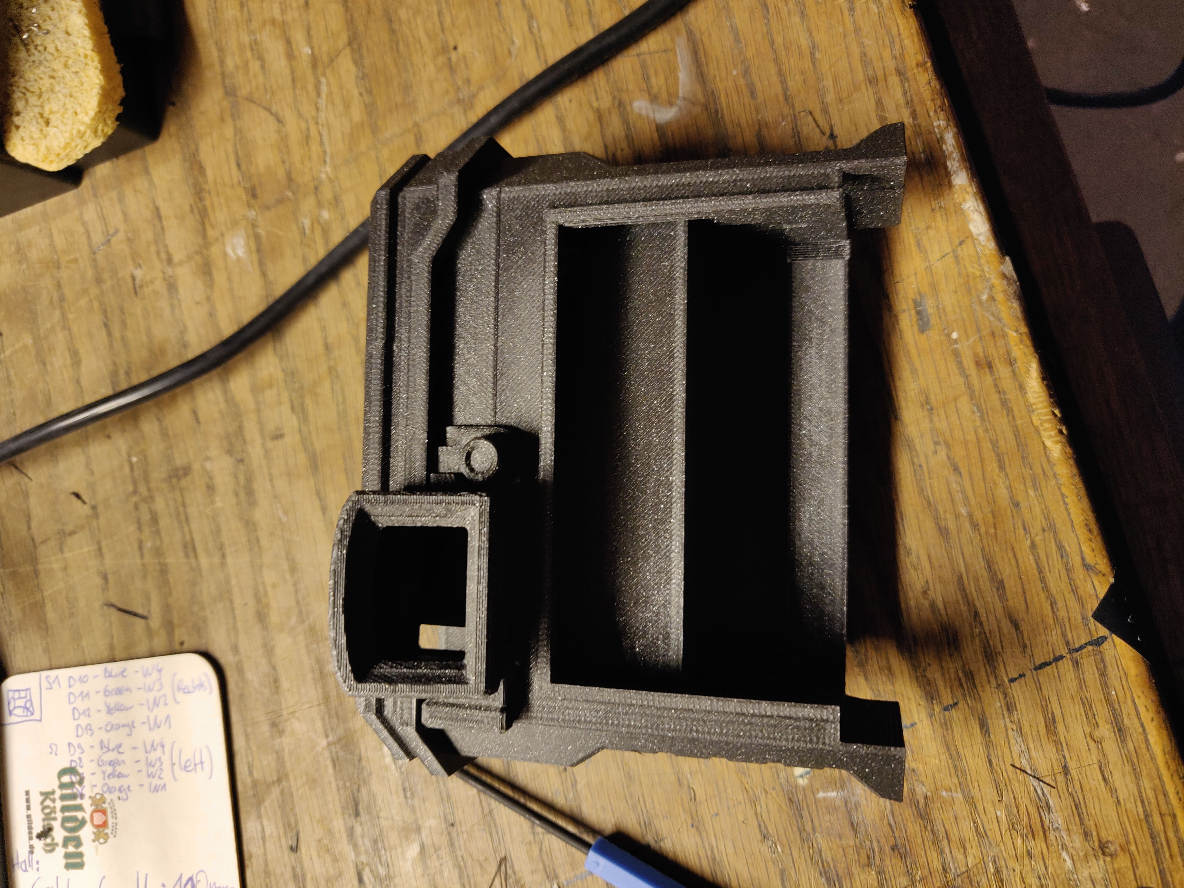
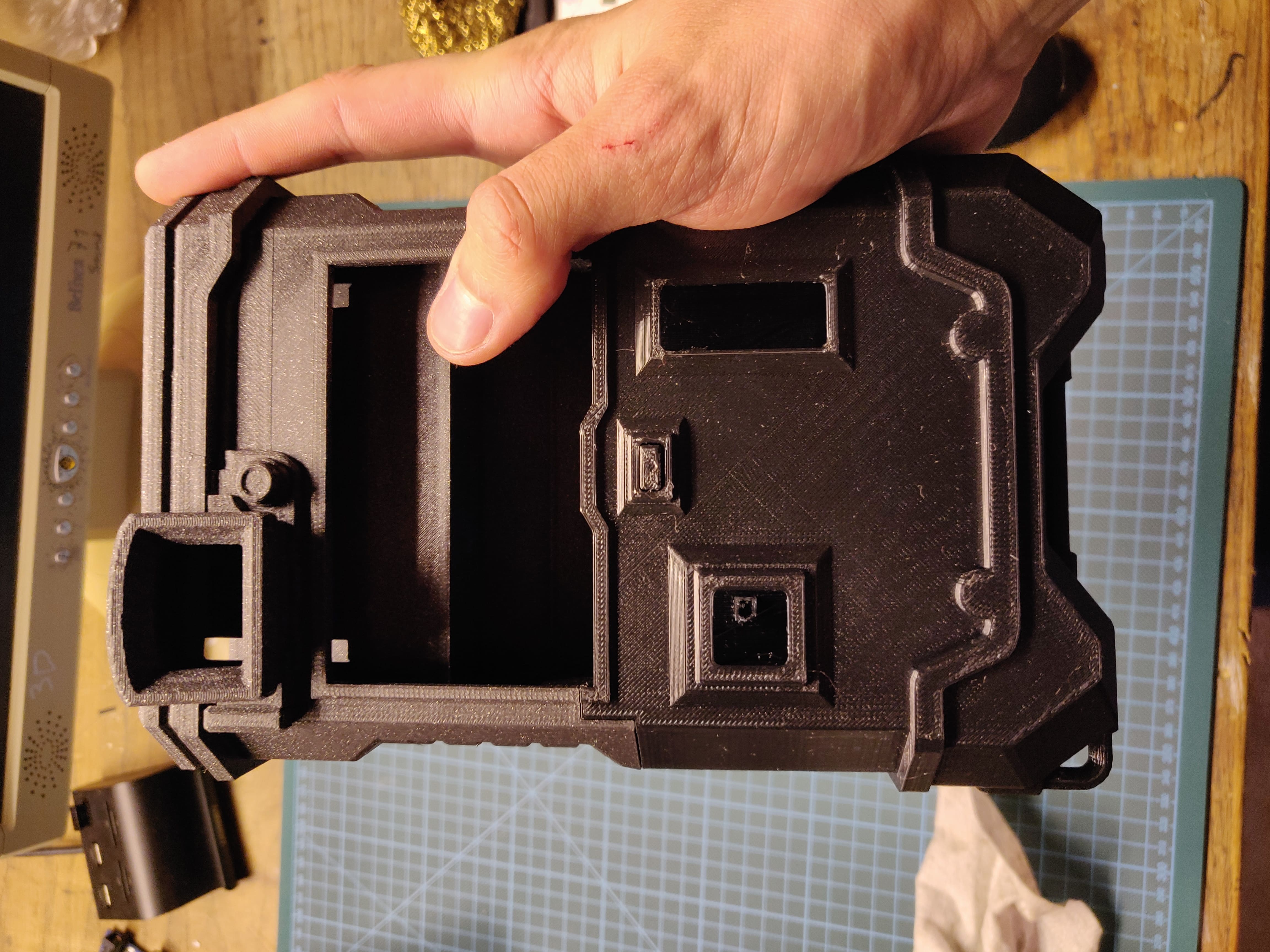
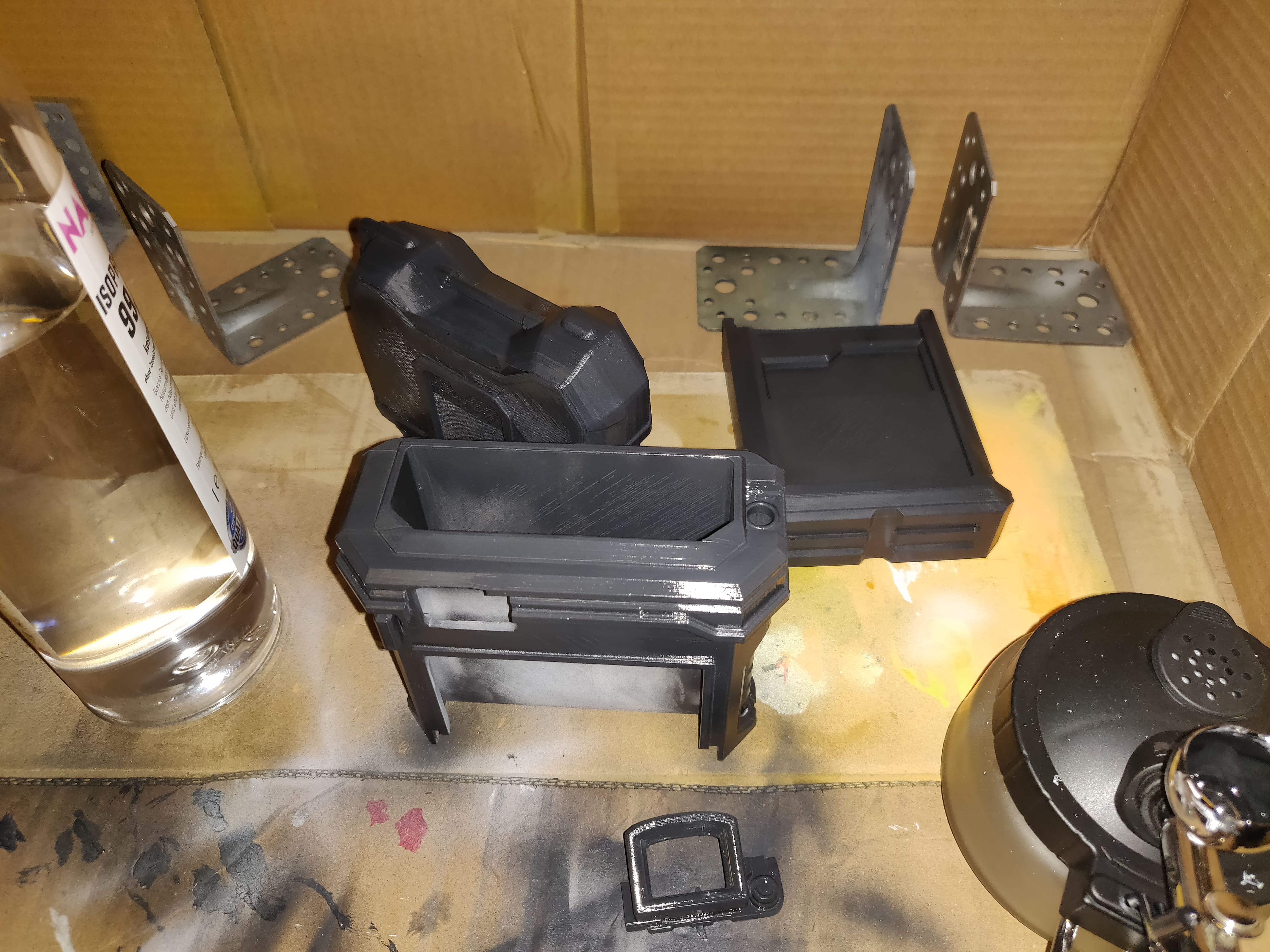
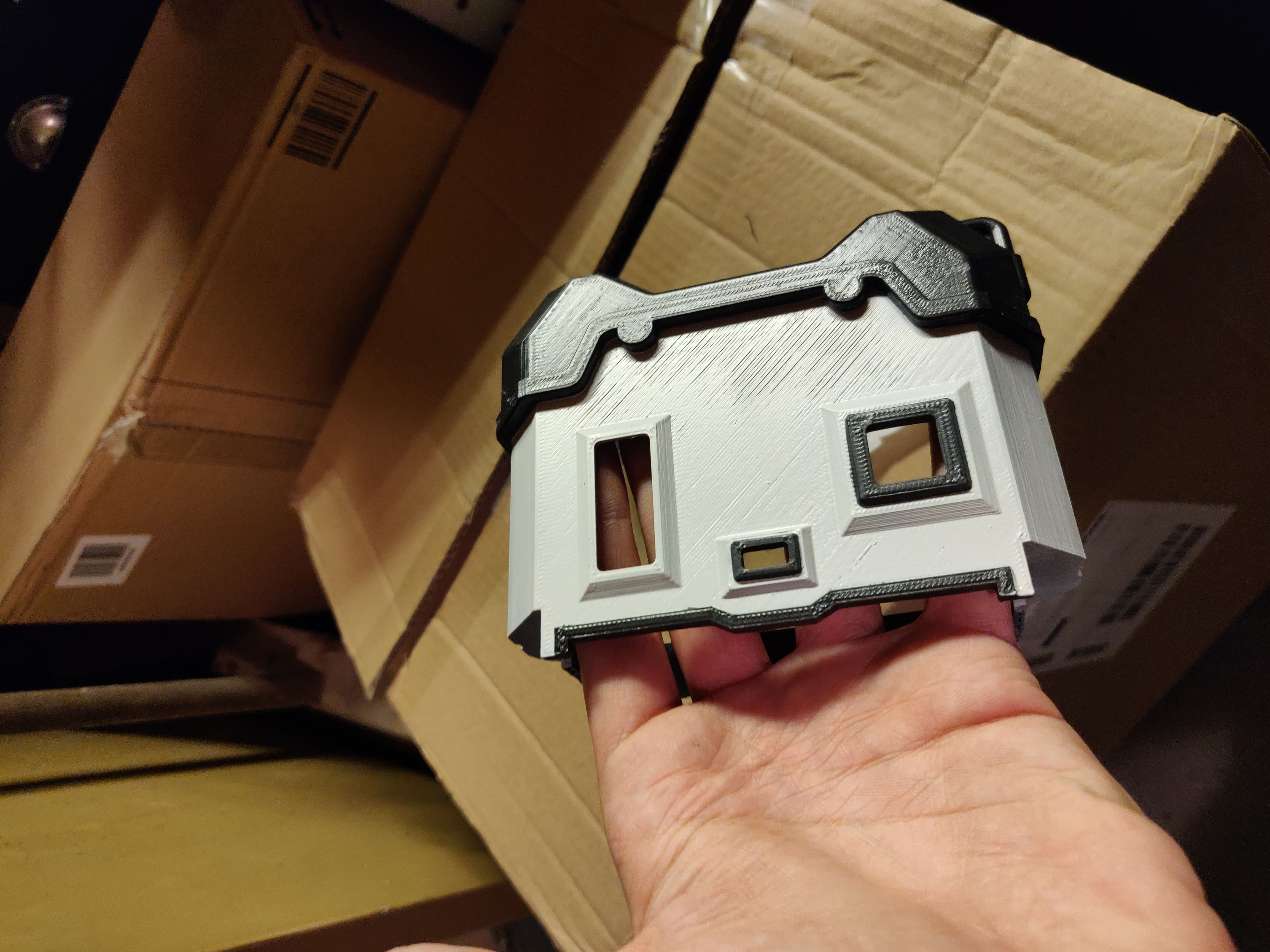
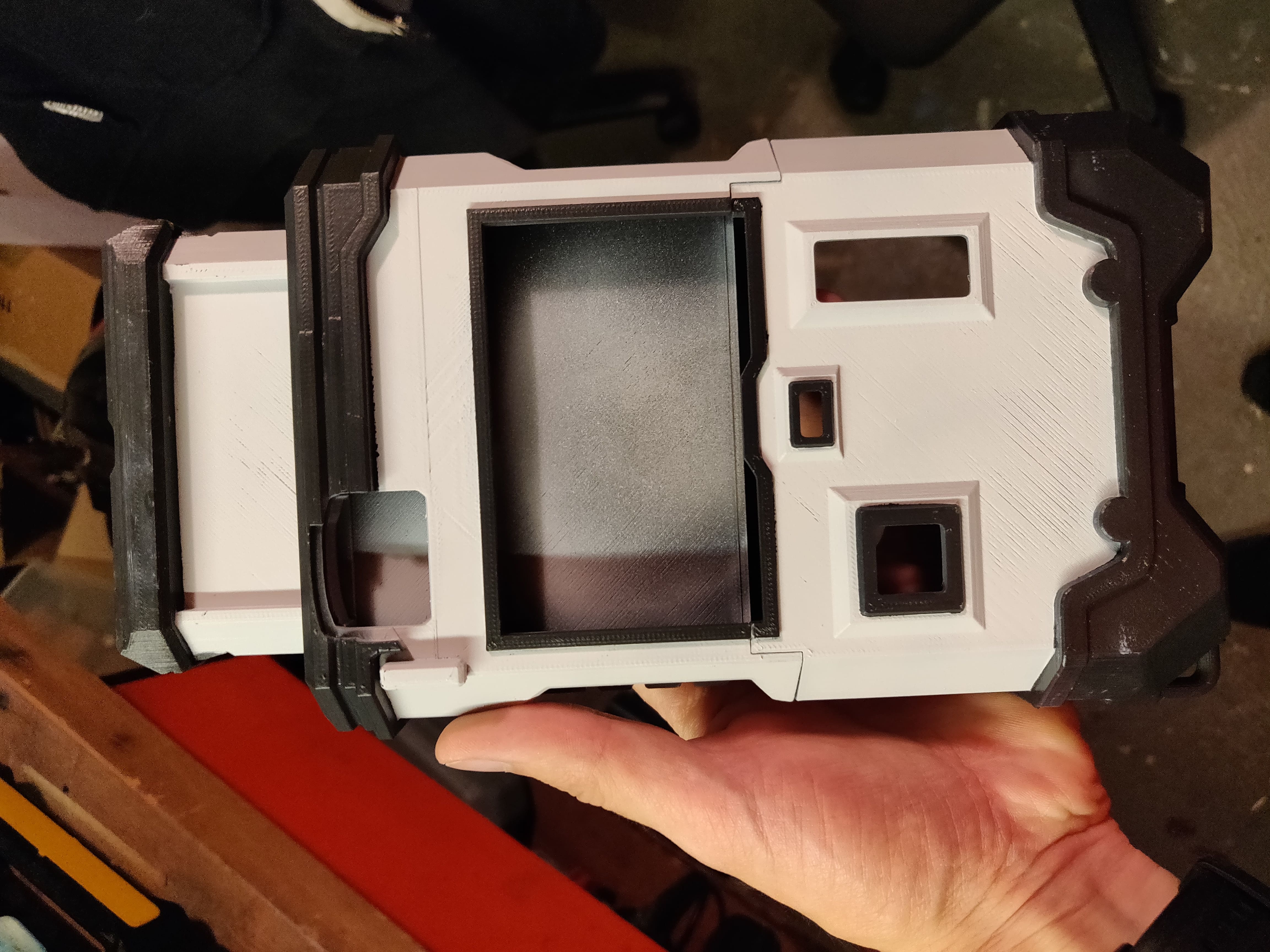
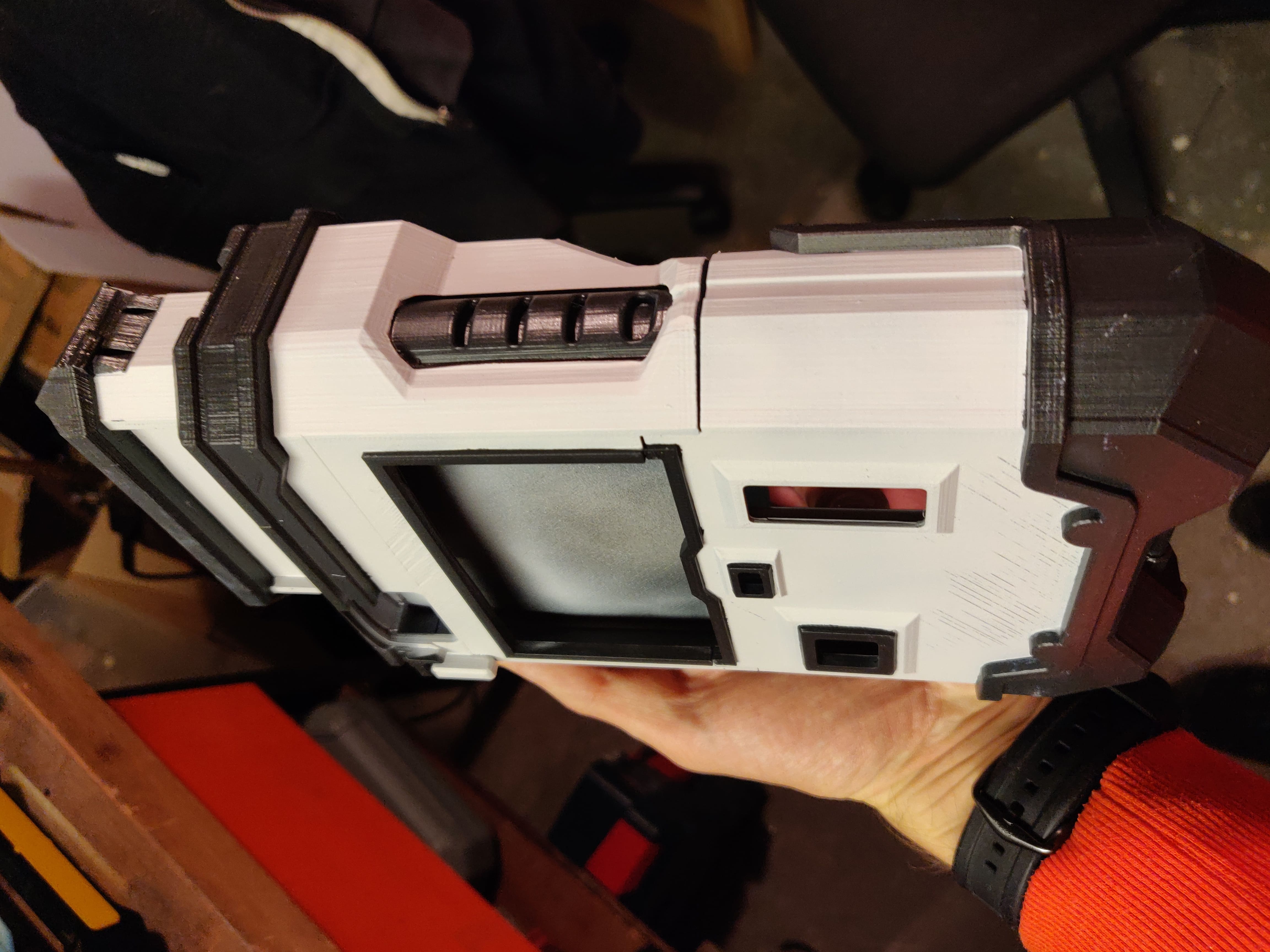
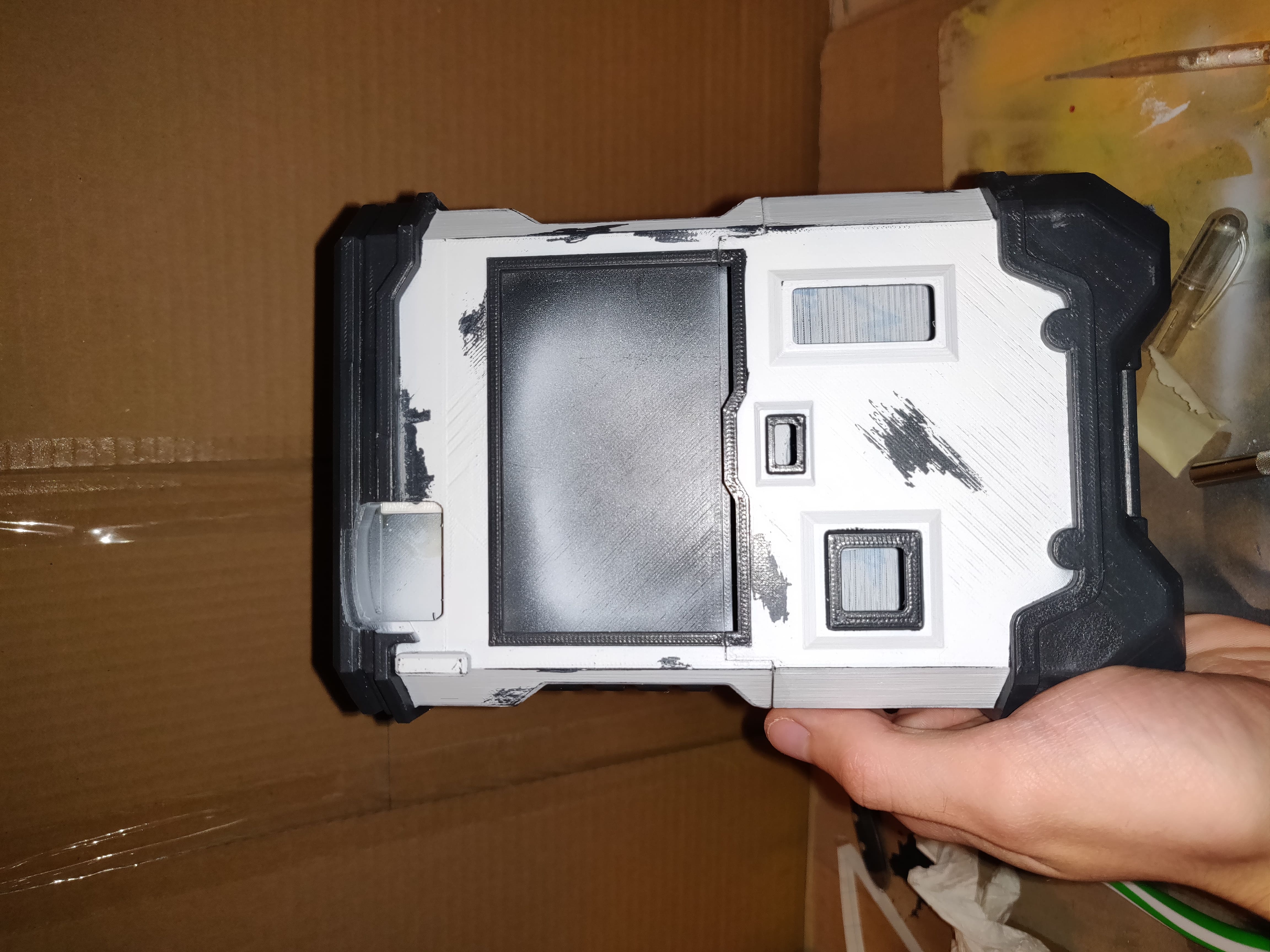
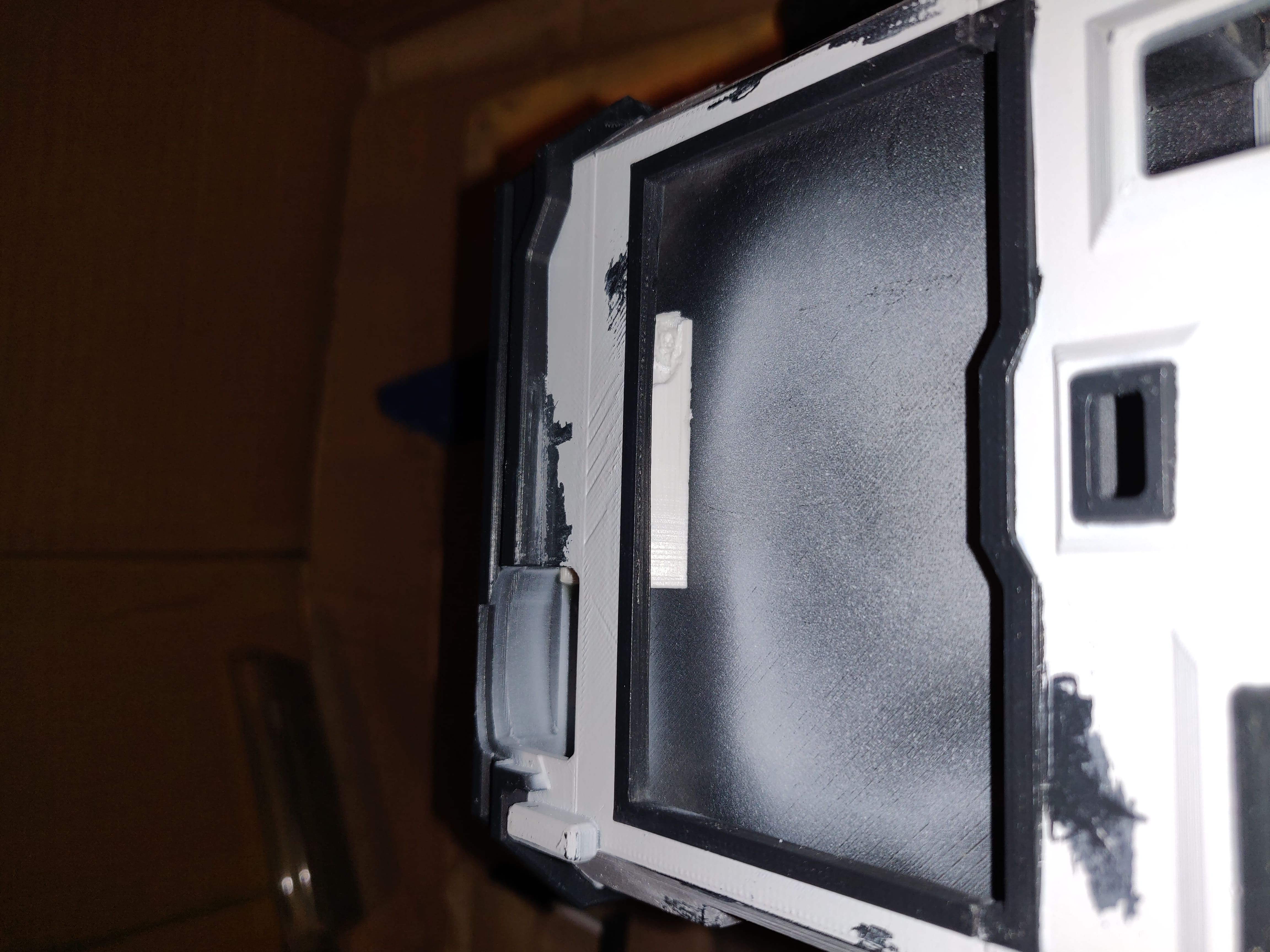
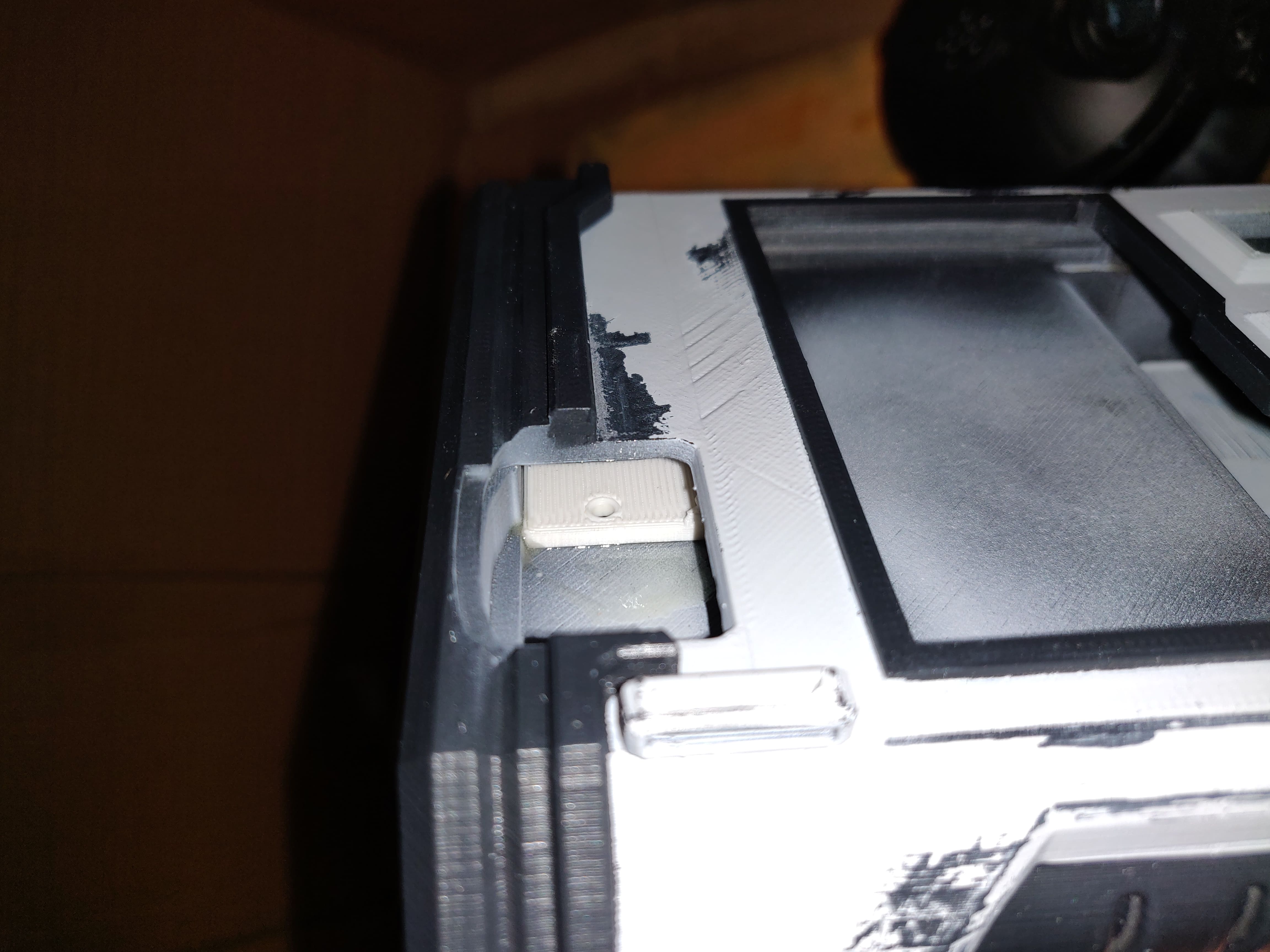
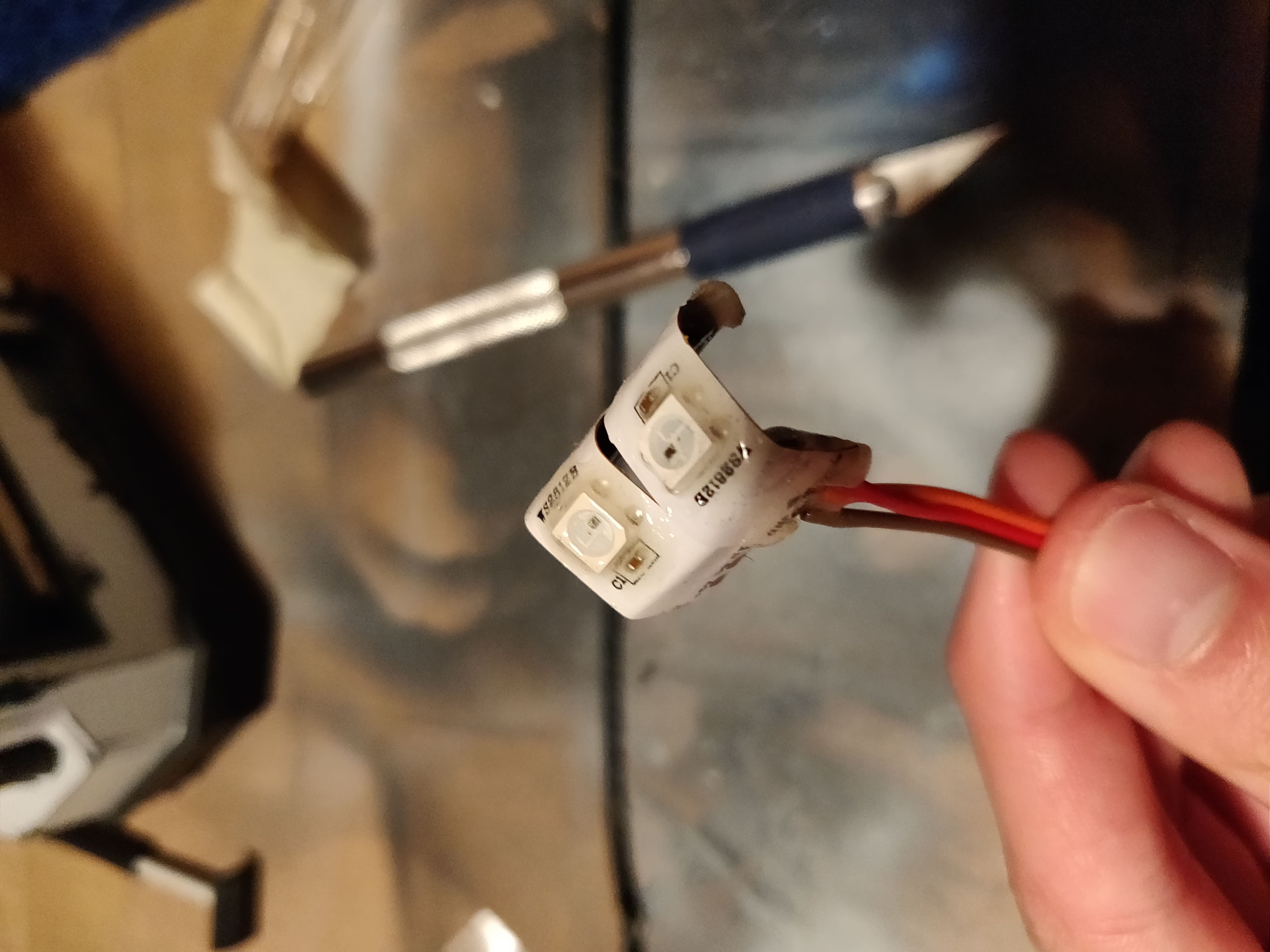
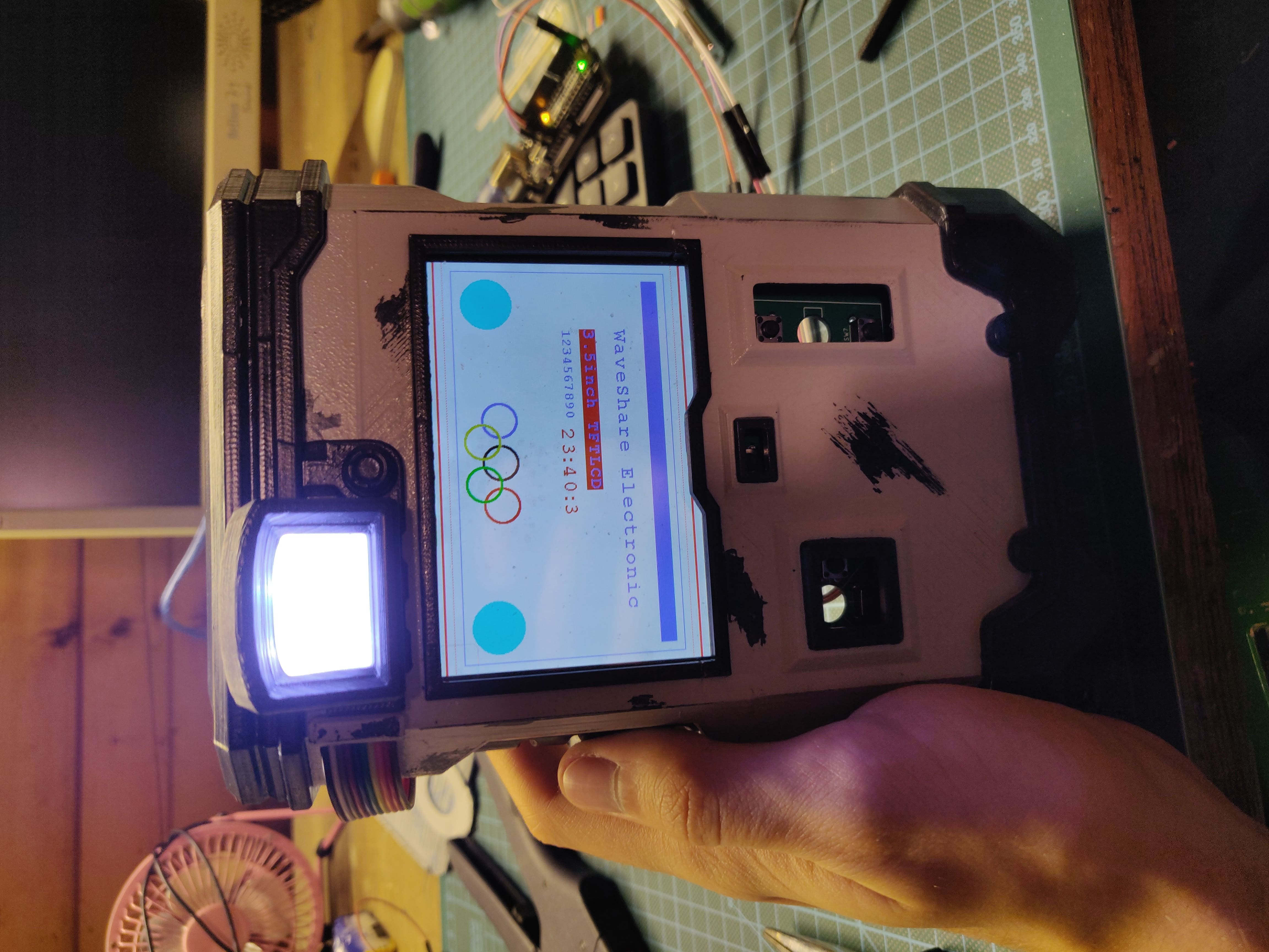
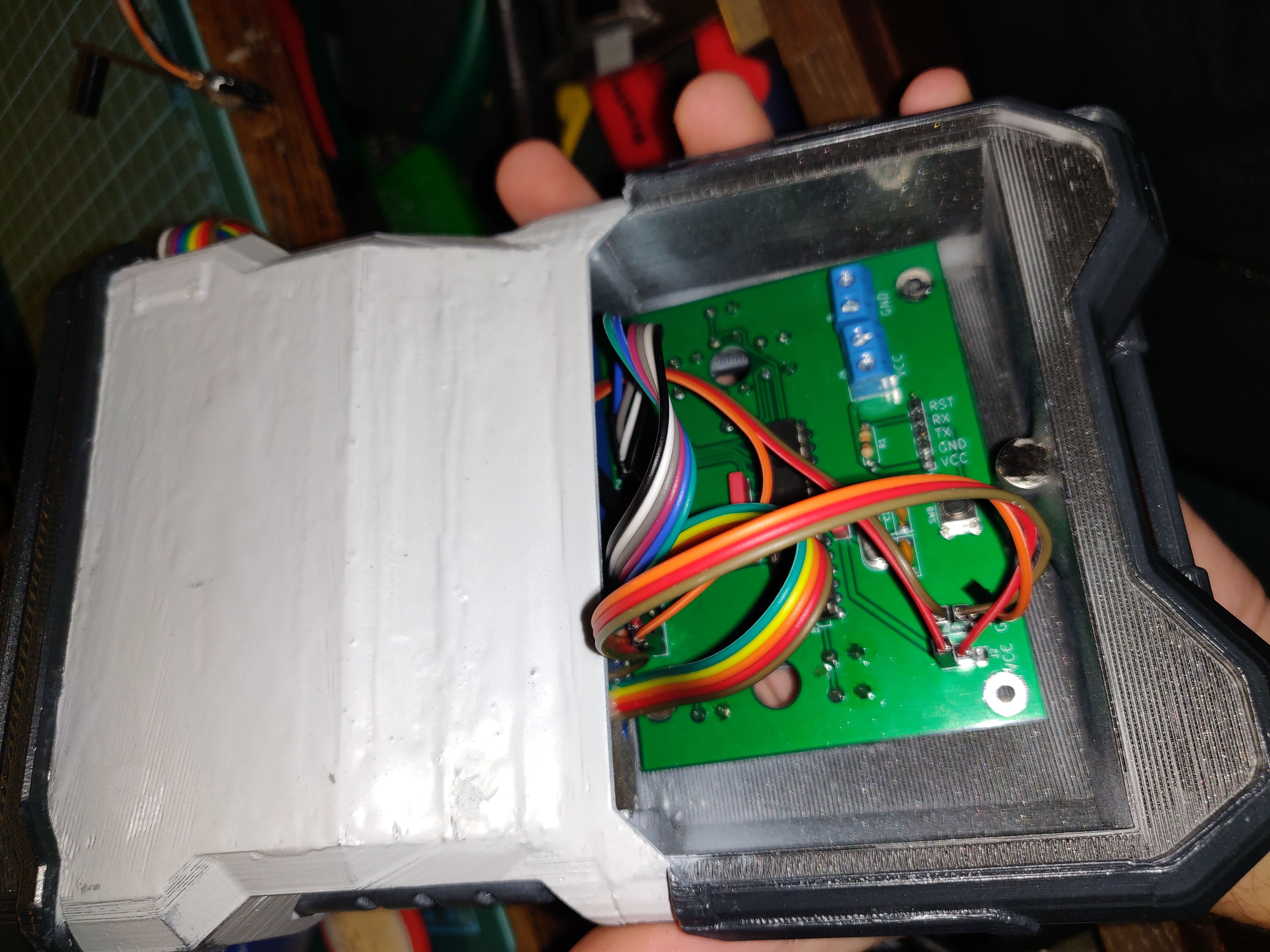
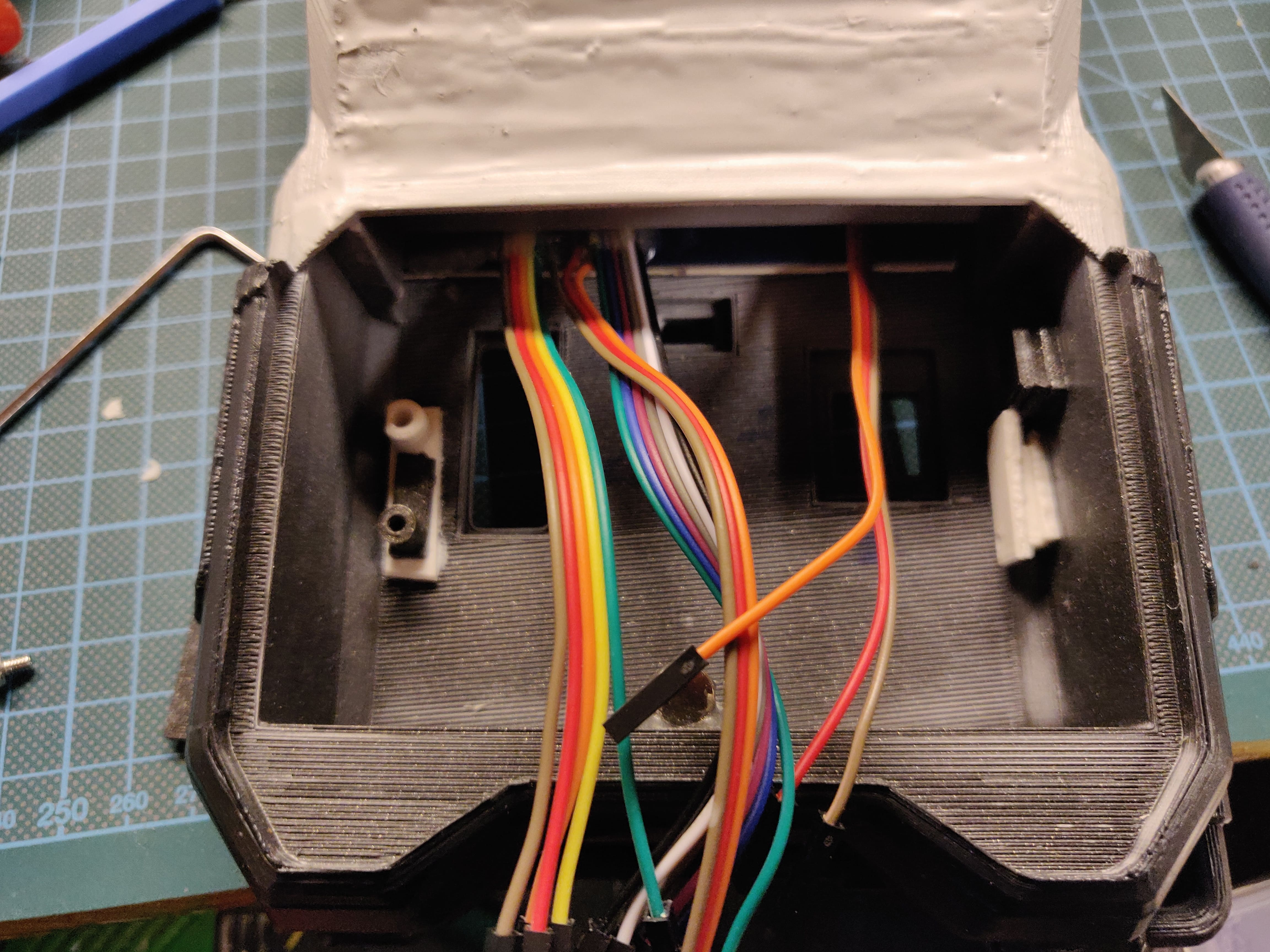
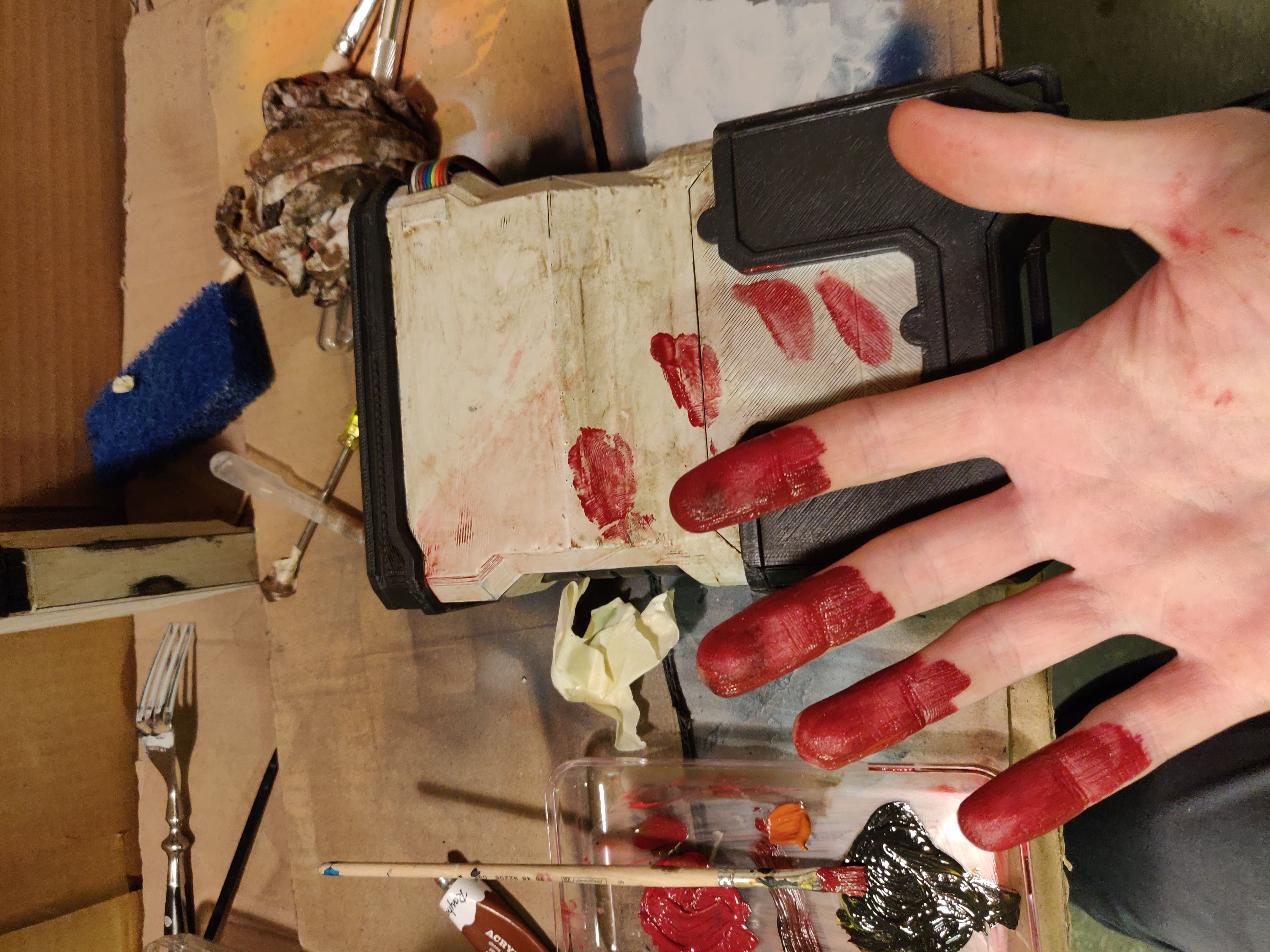
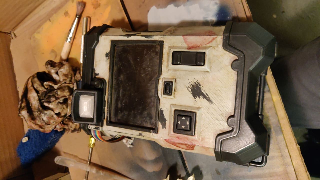
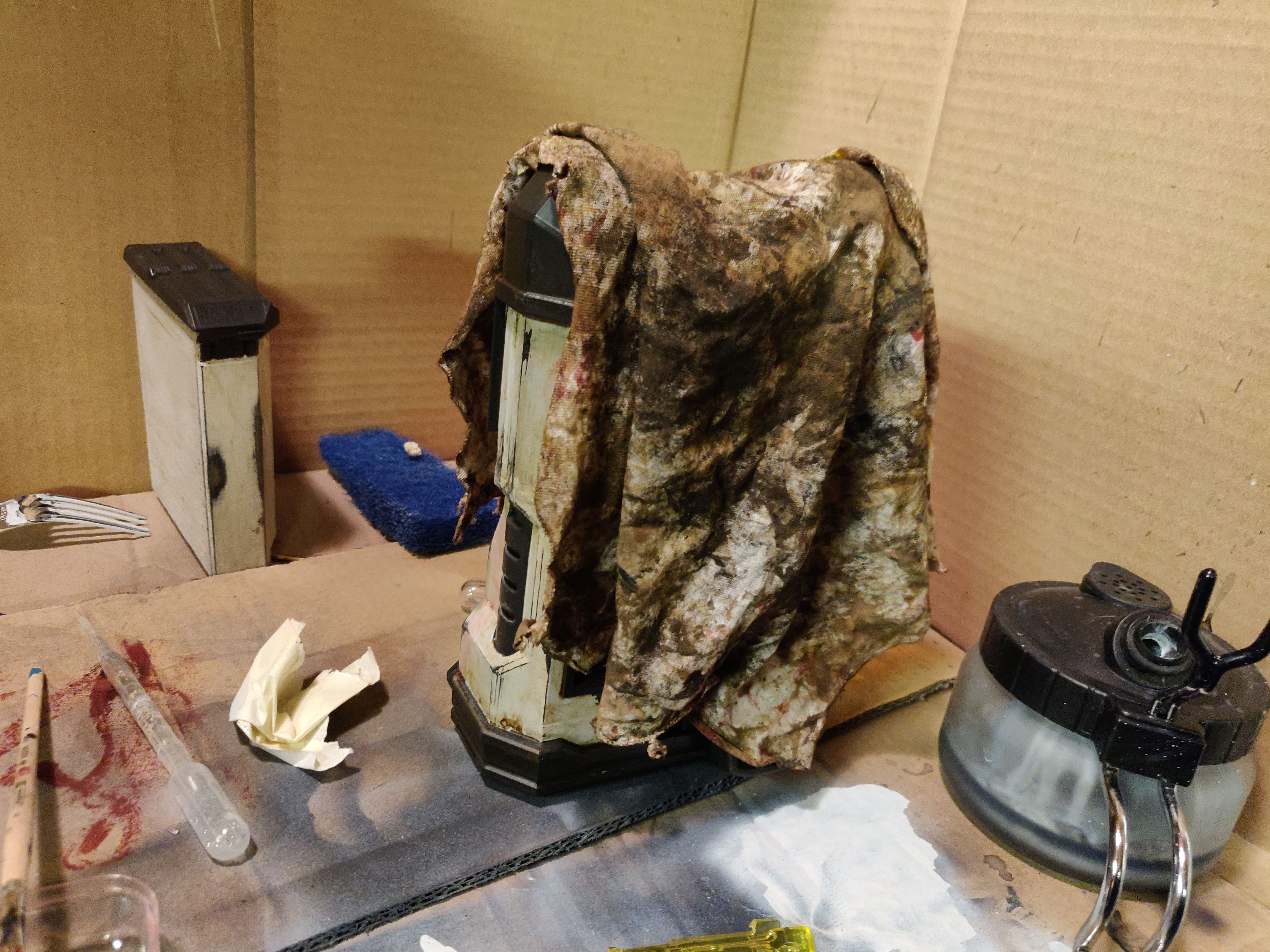
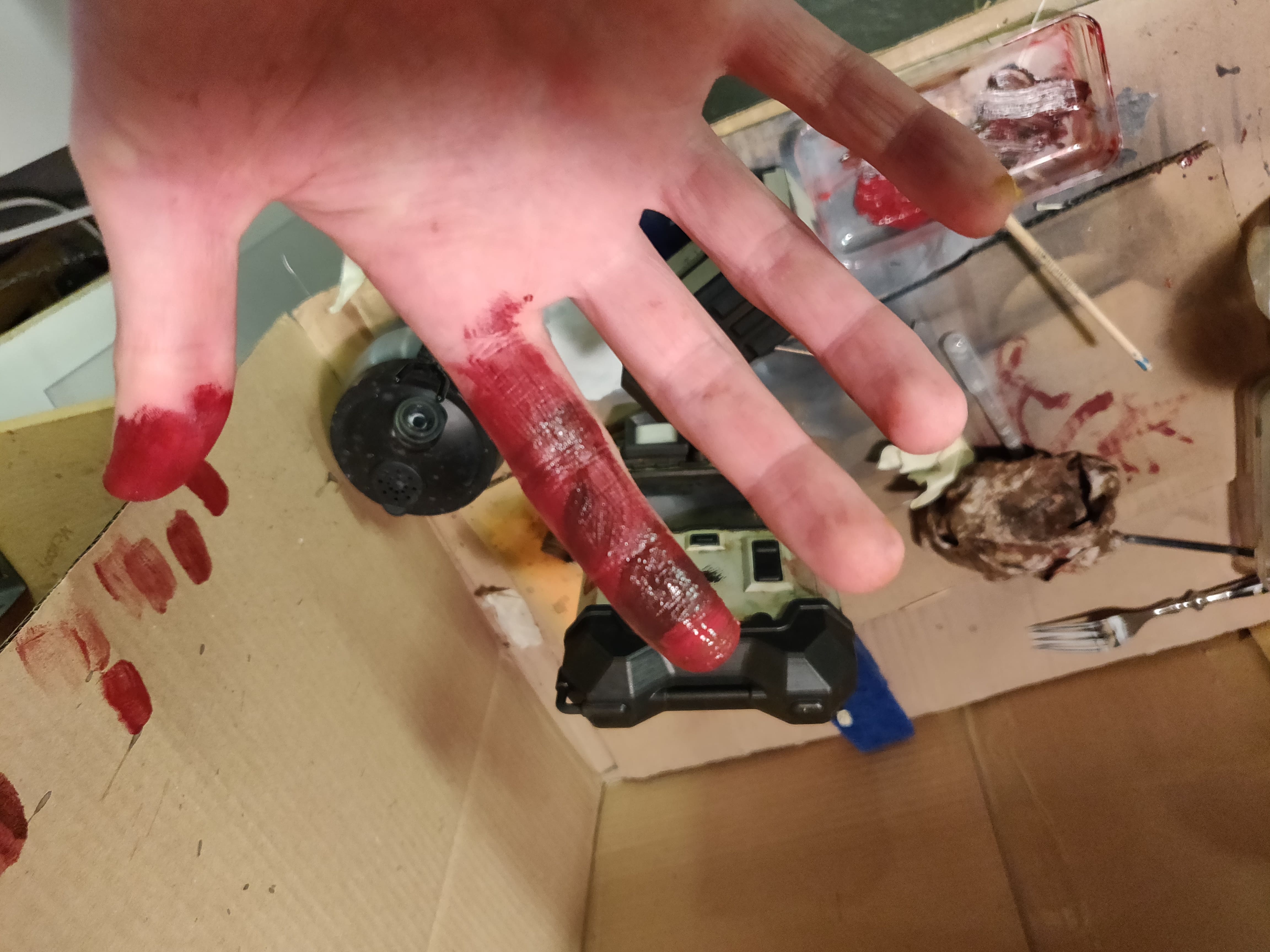
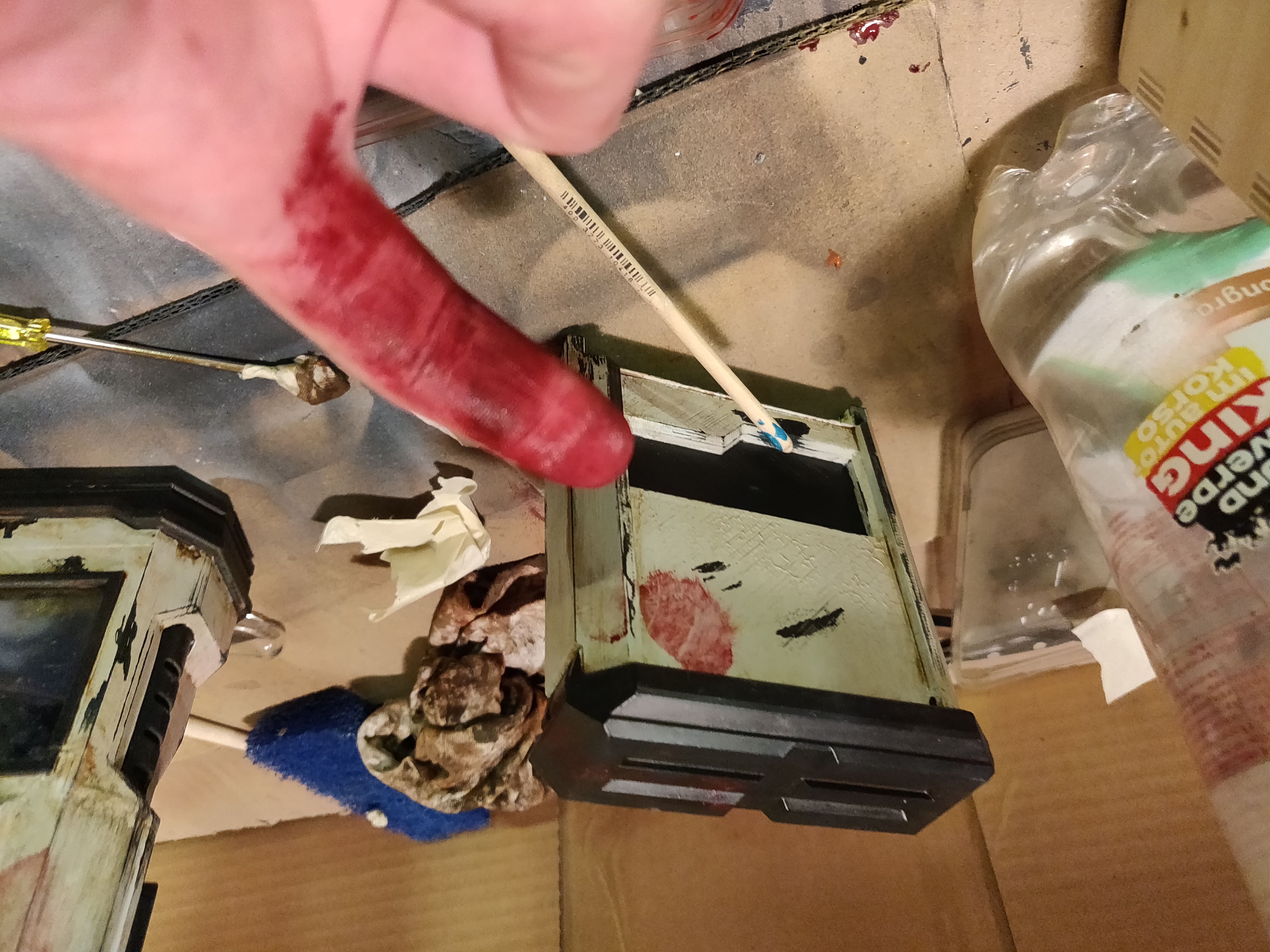
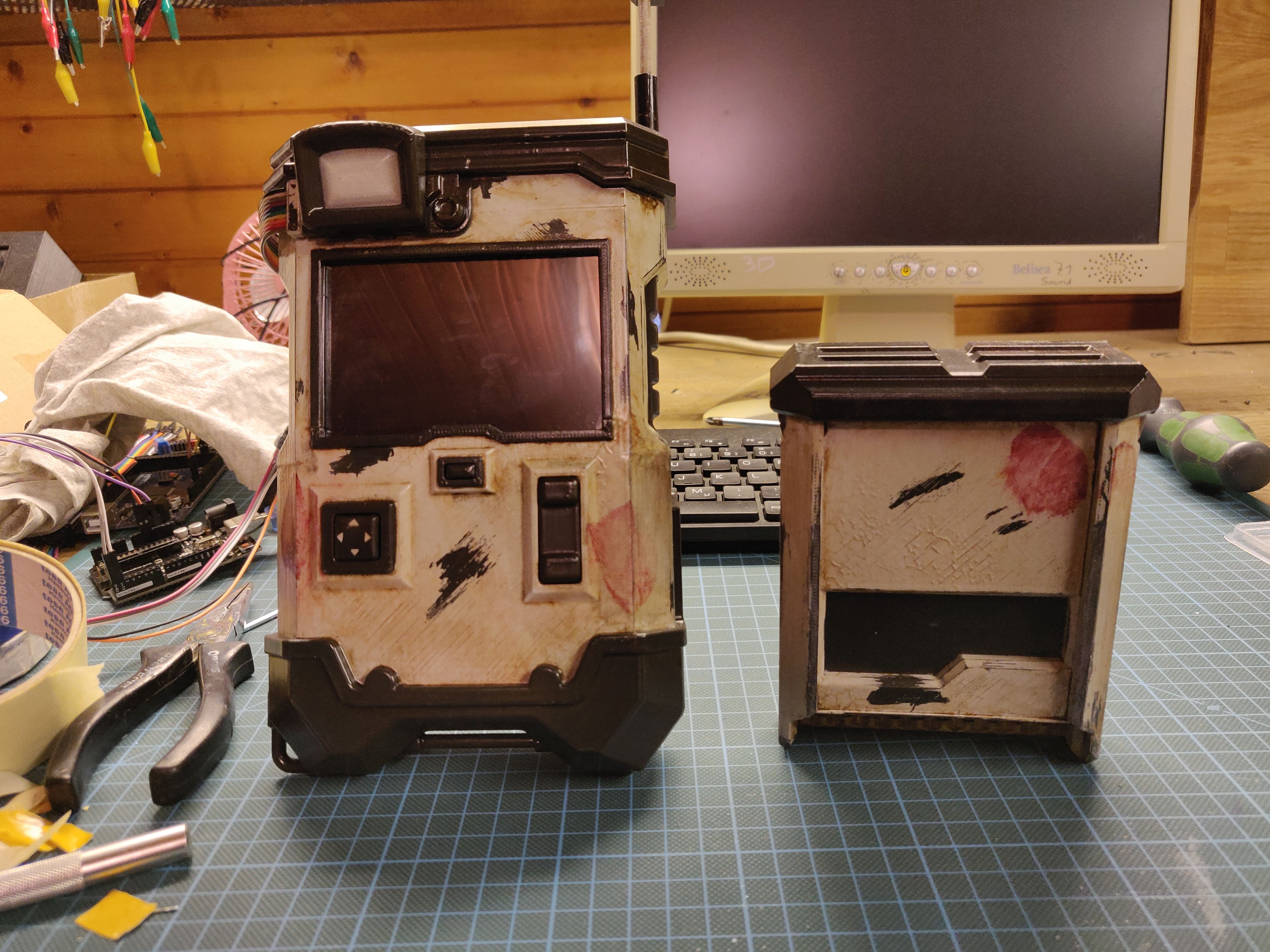
This repo contains all the needed files to create your own 3D printed Echo Com from Borderlands 3. I put lots of images in the repo so the size got quite big, sorry for that 🤷♂️.
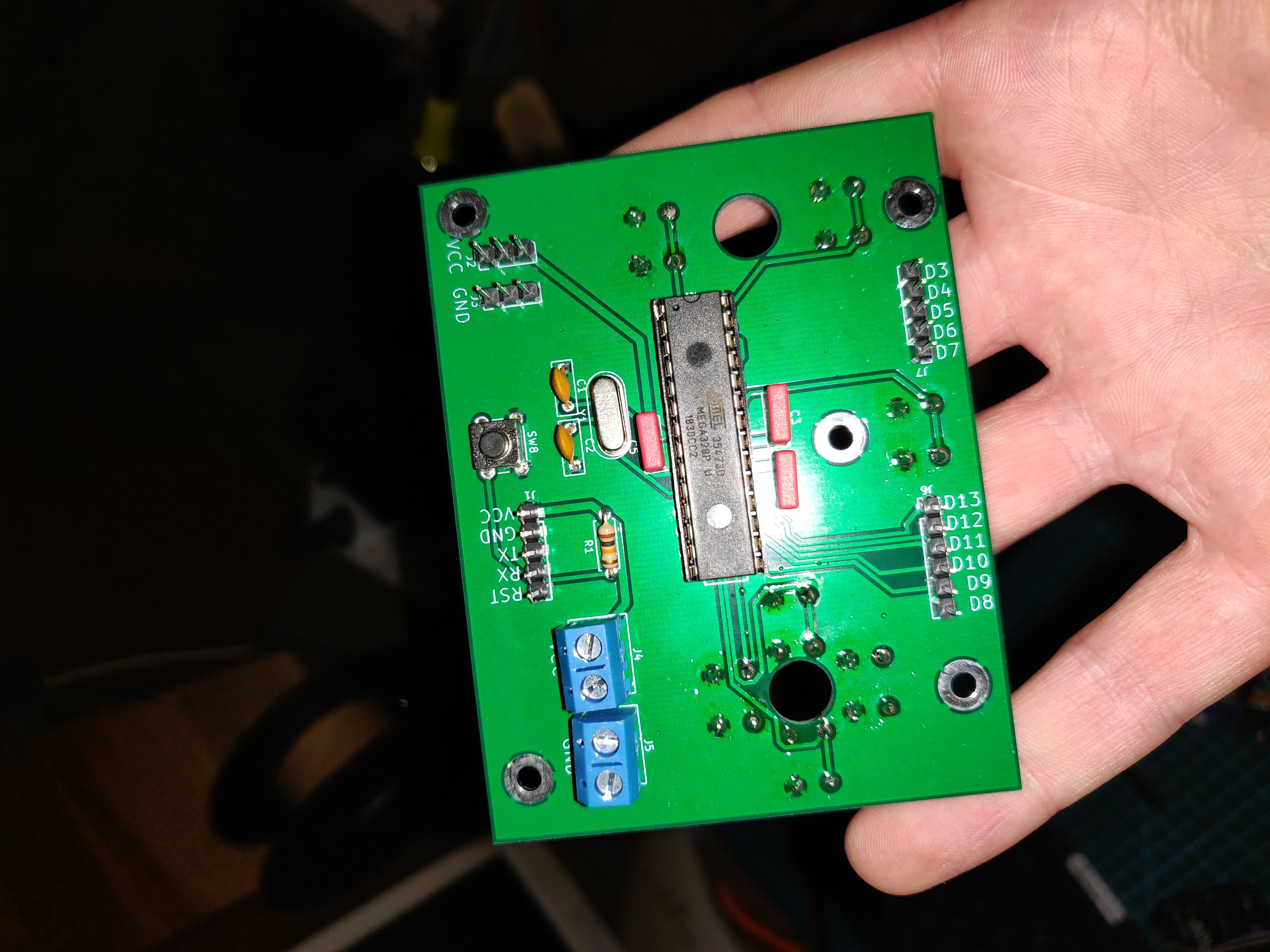
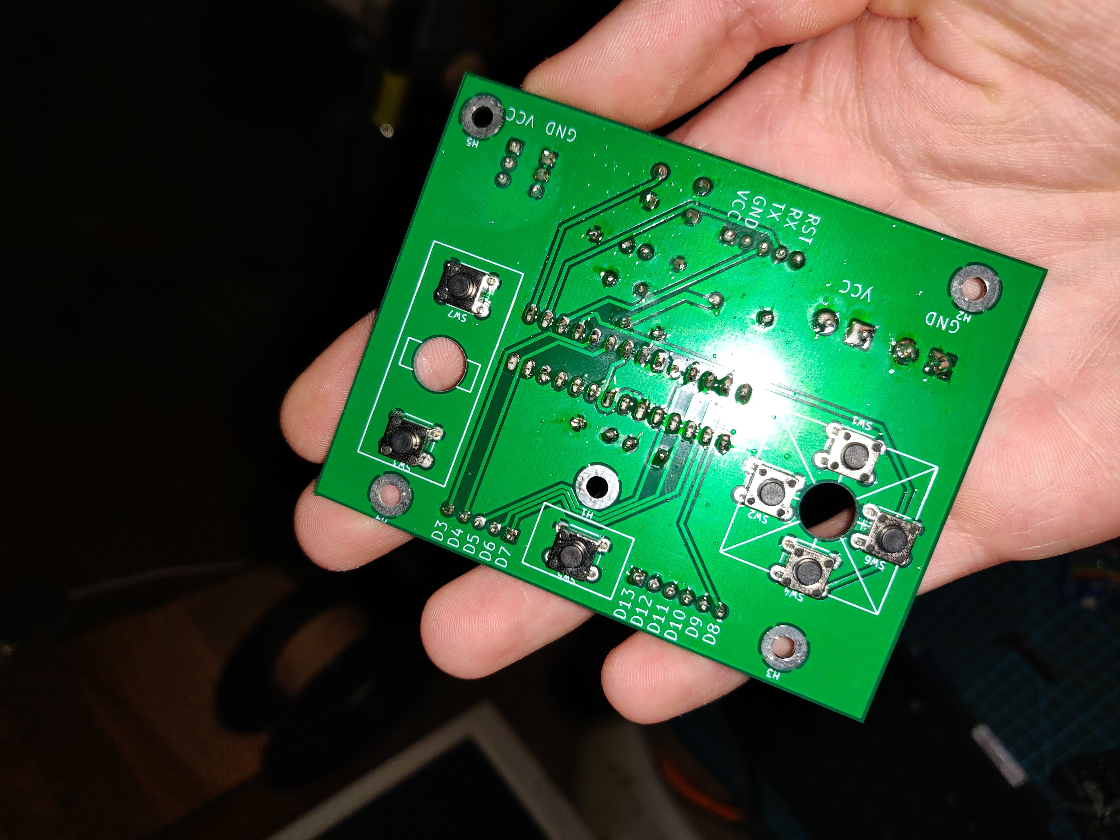
EchoCom is an open-source printed circuit board by LoaderB0T, from the LoaderB0T/Bl3-EchoCom repository on GitHub, published under the GPL-3.0 licence. It is a 2-layer board of 87.8 × 68.2 mm with 30 parts on 26 nets, routed with 282 tracks and 0 vias.
It is built around the ATMEGA328-PU. Its parts include 8 switches, 7 connectors, 5 capacitors, 1 resistor and 1 IC. It belongs with the AVR (ATmega, ATtiny) boards of this library.
This repo contains all the needed files to create your own 3D printed Echo Com from Borderlands 3. I put lots of images in the repo so the size got quite big, sorry for that 🤷♂️.
If you need additional information or have any questions please just open an issue and I will try to answer them 😀. And please, if you decide to give it a shot and you use my model, please please send me pictures of the result! :) Just open an issue here to show off your amazing work.
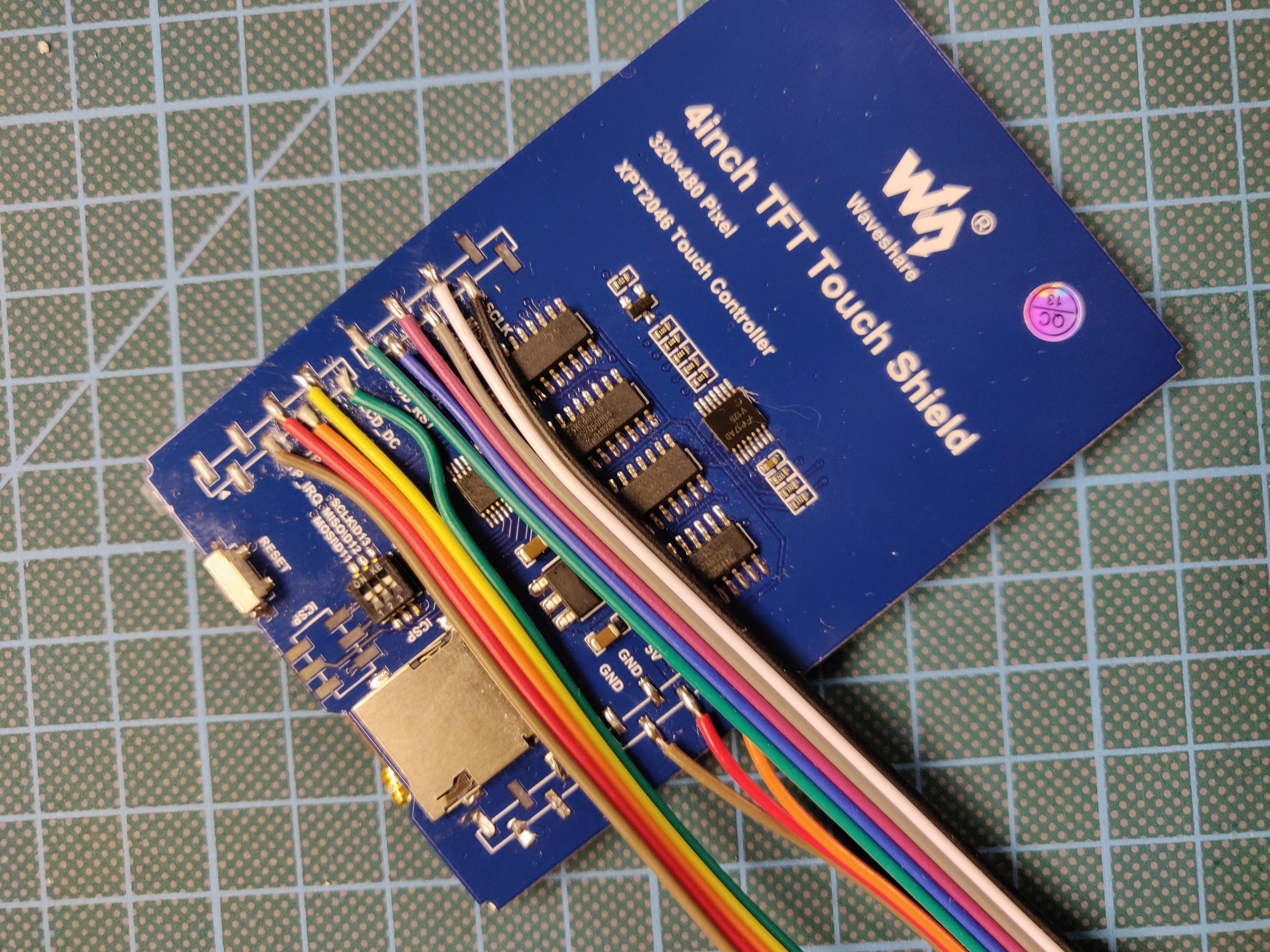
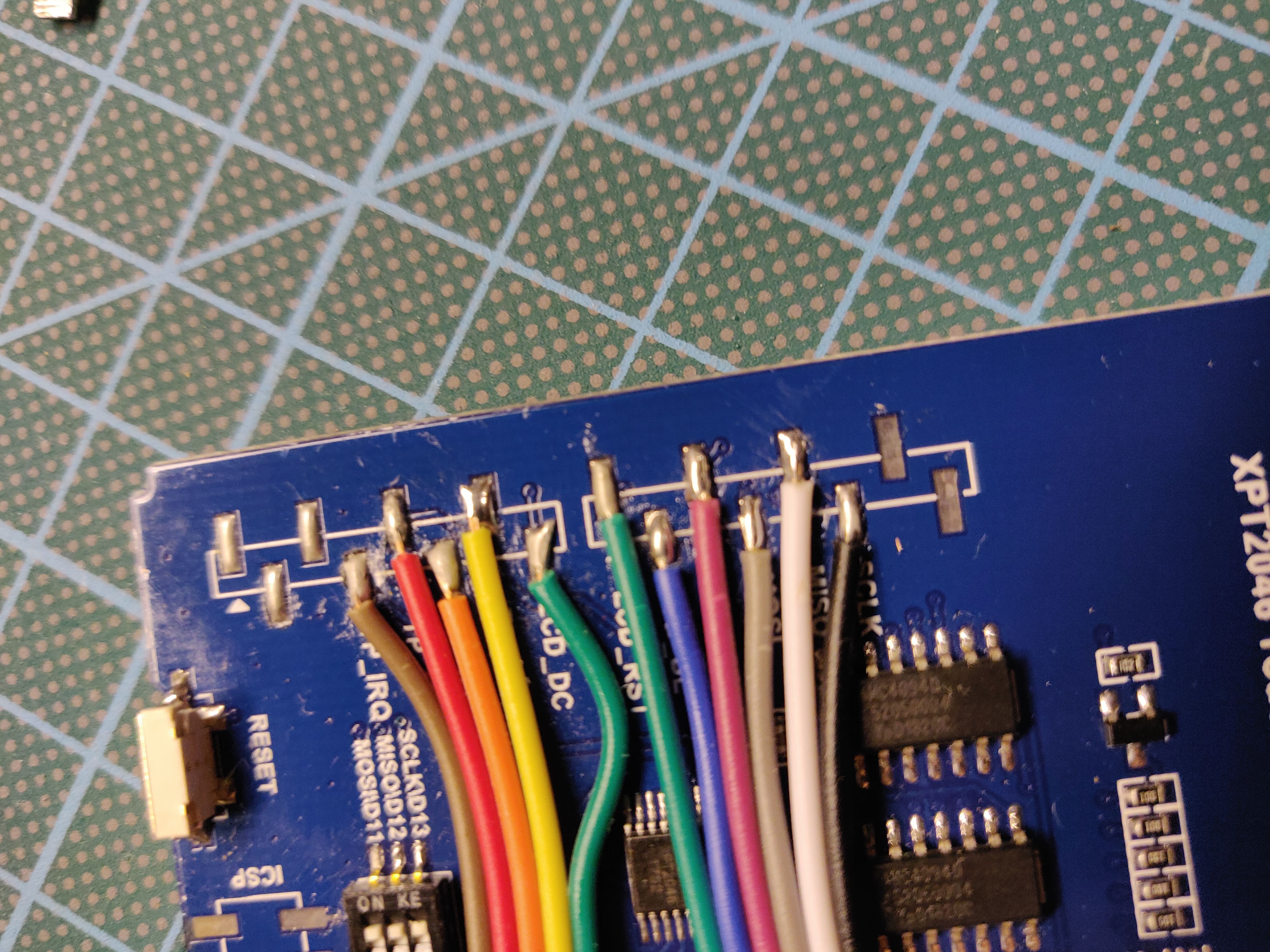
pcb folder.The code is very, very unfinished! I recommend Visual Studio Code to edit the code. The code is a PlatformIO project, so I recommend the PlatformIO extension for VSCode.
 |  |  |
 |  |  |
 |  |  |
 |  |  |
 |  |  |
 |  |  |
 |  |  |
 |  |  |
 |  |  |
 |  |  |
 |  |  |
 |  |  |
 |  |
| Qty | Value | Footprint | References |
|---|---|---|---|
| 5 | C | Capacitor_THT:C_Rect_L7.0mm_W2.5mm_P5.00mm | C1, C2, C3, C4, C5 |
| 5 | MountingHole_Pad | MountingHole:MountingHole_3.2mm_M3_Pad | H1, H2, H3, H4, H5 |
| 1 | ATMEGA328-PU | ATMEGA328-PU:DIL28 | IC1 |
| 1 | Conn_01x05_Male | Connector_PinHeader_2.54mm:PinHeader_1x05_P2.54mm_Vertical | J7 |
| 1 | Conn_01x06_Male | Connector_PinHeader_2.54mm:PinHeader_1x06_P2.54mm_Vertical | J6 |
| 1 | Conn_GND | Connector_PinHeader_2.54mm:PinHeader_1x03_P2.54mm_Vertical | J3 |
| 1 | Conn_Programmer | Connector_PinHeader_2.54mm:PinHeader_1x05_P2.54mm_Vertical | J1 |
| 1 | Conn_VCC (5v) | Connector_PinHeader_2.54mm:PinHeader_1x03_P2.54mm_Vertical | J2 |
| 1 | Crystal | Crystal:Crystal_HC49-4H_Vertical | Y1 |
| 1 | R | Resistor_THT:R_Axial_DIN0207_L6.3mm_D2.5mm_P7.62mm_Horizontal | R1 |
| 1 | SW_Cross_Down | Button_Switch_THT:SW_PUSH_6mm_H5mm | SW1 |
| 1 | SW_Cross_Left | Button_Switch_THT:SW_PUSH_6mm_H5mm | SW6 |
| 1 | SW_Cross_Right | Button_Switch_THT:SW_PUSH_6mm_H5mm | SW2 |
| 1 | SW_Cross_Up | Button_Switch_THT:SW_PUSH_6mm_H5mm | SW4 |
| 1 | SW_Dual_Down | Button_Switch_THT:SW_PUSH_6mm_H5mm | SW7 |
| 1 | SW_Dual_Up | Button_Switch_THT:SW_PUSH_6mm_H5mm | SW3 |
| 1 | SW_Reset | Button_Switch_THT:SW_PUSH_6mm_H5mm | SW8 |
| 1 | SW_Single | Button_Switch_THT:SW_PUSH_6mm_H5mm | SW5 |
| 1 | Screw_Terminal_GND | TerminalBlock:TerminalBlock_bornier-2_P5.08mm | J5 |
| 1 | Screw_Terminal_VCC | TerminalBlock:TerminalBlock_bornier-2_P5.08mm | J4 |
The 28 most common of 30 parts.
It measures 87.8 × 68.2 mm and has 2 copper layers, 1.6 mm thick.
30 parts, built around the ATMEGA328-PU. The full list of its parts is on this page, with links to each part's symbol and footprint where PCBKit's library has them.
From the LoaderB0T/Bl3-EchoCom repository on GitHub, at the commit this page was made from: the board is pcb/EchoCom.kicad_pcb. PCBKit opens the board in the browser, with nothing to install.
Its repository publishes it under the GPL-3.0 licence: you may reuse it on that licence's terms (keep the author's notice, and for a copyleft licence share your changes alike).


peej/lumberjack-keyboard
5x12 ortholinear through-hole component keyboard PCB for standard 60% cases

peterheinrich/InternetOverSpaghetti
Transmitting IP packages over a pair of spaghetti thus demonstrating how media independent IP really is.

