
2 layers228 × 98 mm

 brickbots/HandiPi814
Handheld RPI4 based computer with keyboard and display
Handipi kb is an open-source printed circuit board by brickbots, from the brickbots/HandiPi repository on GitHub, published under the MIT licence. It is a 2-layer board of 104.9 × 75.2 mm with 95 parts on 68 nets, routed with 347 tracks and 11 vias.
It is built around the ATMEGA328-PU. Its parts include 38 diodes, 37 switches, 5 capacitors, 4 resistors and 3 connectors. It belongs with the keyboards and input and lEDs and displays boards and the AVR (ATmega, ATtiny) boards of this library.
Handheld RPI4 based computer with 36-key tactile keyboard and display
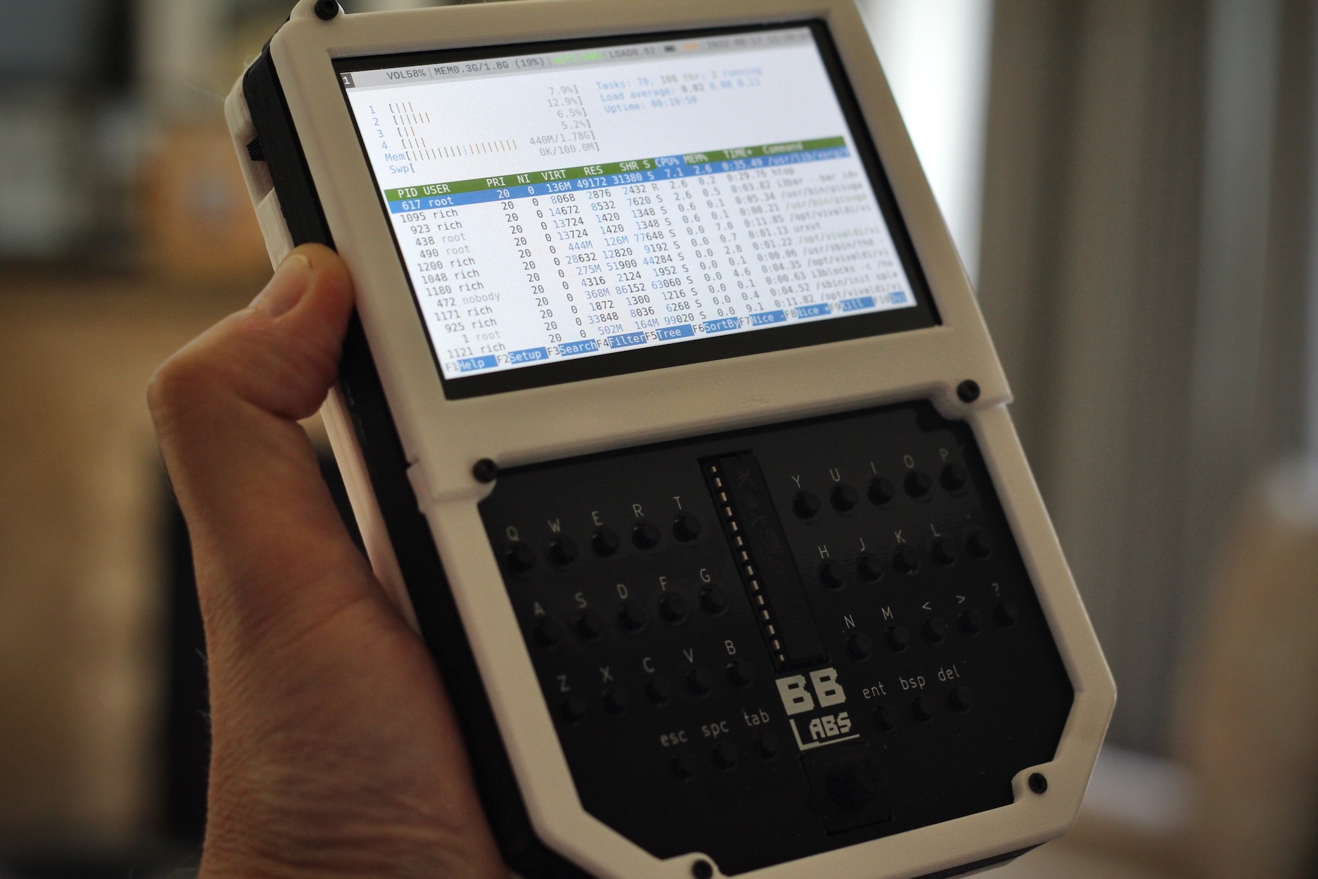
Glad you asked.. it's a fully functional linux computer with:
It runs for about 4 hours with general terminal use and is pretty useful on it's own, but you can hook up external monitors and other USB peripherals if you need more screen or typing space.
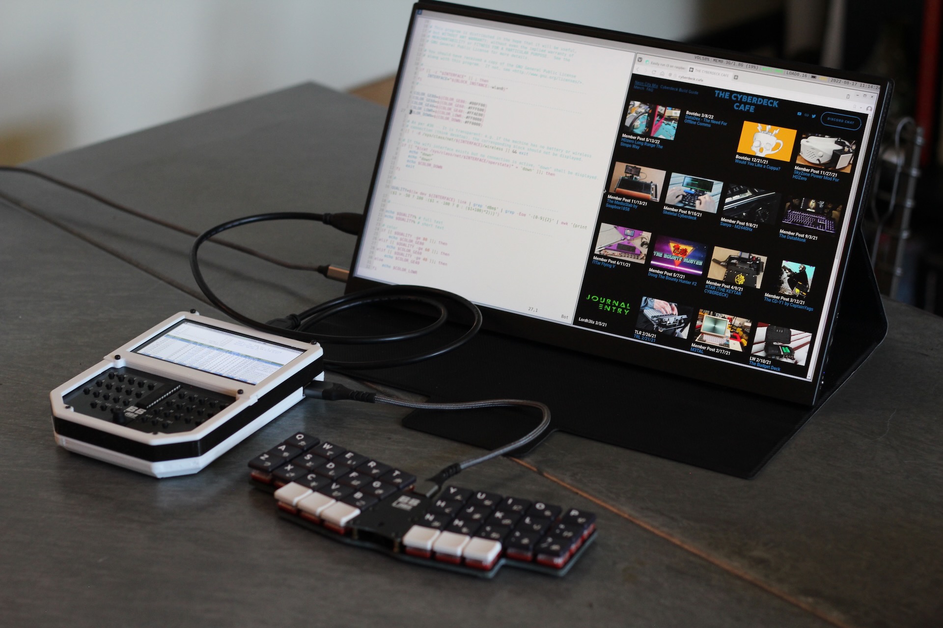
The keyboard runs QMK and interfaces to the Pi via USB, so it's fully configurable. I really like the Miryoku layout and use it on all my keyboards...so that's what the physical button layout is based around. The switches are Diptronic DTS63K tactiles with 1Nm of actuation force. They look the same as the generic ones, but it's worth the few extra dollars as they feel so much better to type on. It's still a thumb-typing experience, but the limited number of keys and the well thought out layering system of Miryoku makes it a suprisingly useful keyboard!
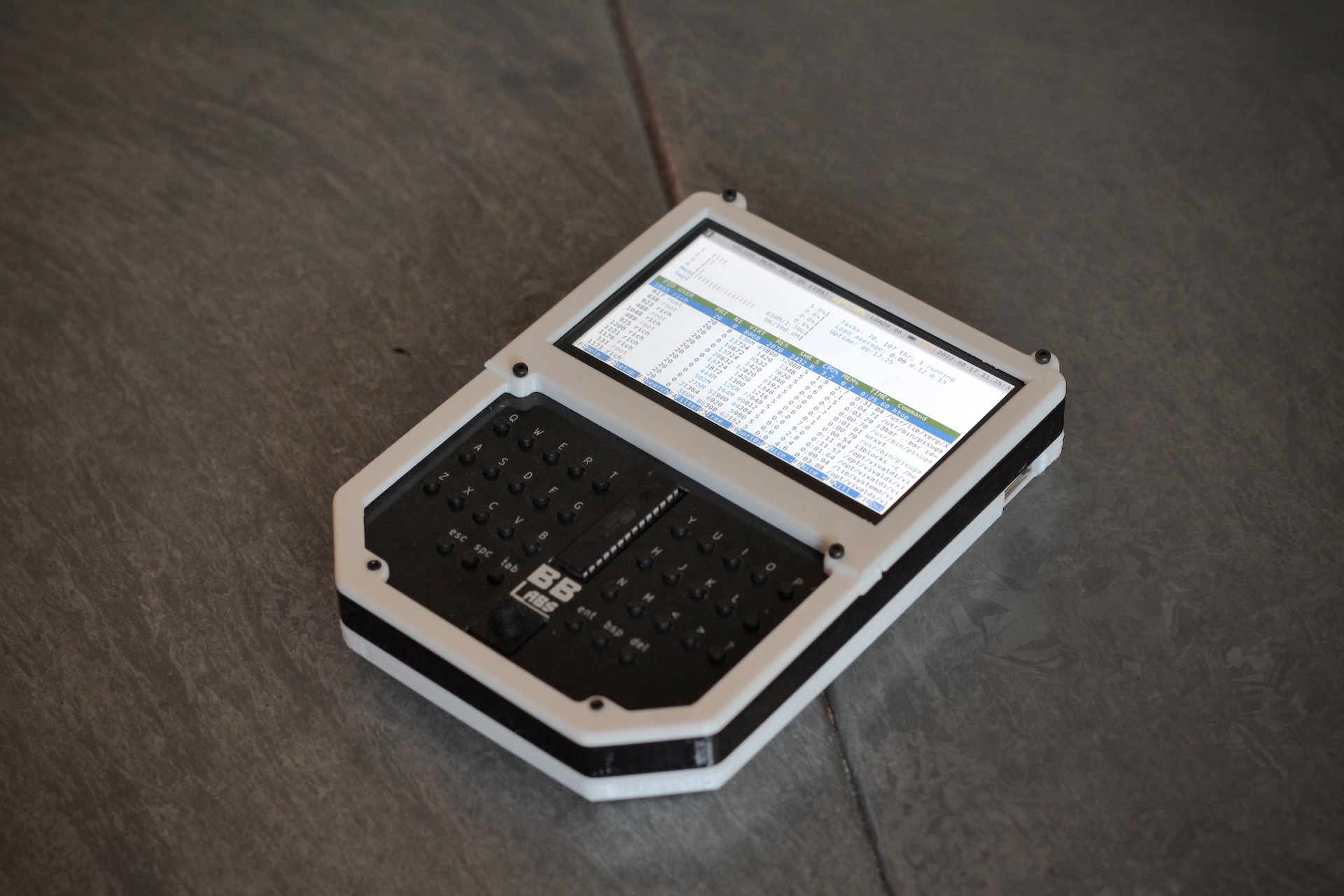
Well.. it all started when I picked up the PCB's for the PICOmputer made by Bobricius. It's a sort of carrier board for the Raspberry Pi PICO that includes a keyboard using 6mm pushbutton tactile switches and a display. It's simple, but it really opens up some fun potential. I ended up 3d printing a case for mine and adding a battery with charging to make it a neat little toy to play with. Along the way, I was really impressed with how well the keyboard actually worked.. even though I didn't follow his advice and bought cheaper switches with higher actuation force.
When it came time to replace the Orange Pi based desktop PC I used at my workbench I grabbed the RPI4 I ordered early in the pandemic and had been hording. I was just going to put it in a boring case, but then I got to thinking about the PICOmputer and wondering if I could build a case with a screen and keyboard. I'd still use the computer with a monitor, keyboard and trackball at my desk most of the time, but I could grab it and have my workbench computer with me if I wanted to go hack at a friends house or makerspace.
So that's where the idea came from, and the rest was just balancing the screen size with portability and thinking hard about thumb-typing layouts....
I've built a good number of keyboards in my time, and even designed a couple. Most of the keyboards I've built rely on a pre-assembled Pro-Micro style controller, but I just didn't think I'd have the space to use that trick here. There are many good refrence designs for the basic AtMega circuit, and I can solder surface mount diodes okay, but I realy didn't think I'd have the skills to do a fine-pitch AtMega surface mount package without a lot of pain and suffering. It was then that I remembered the first keyboard I ever built.... the Plaid!
The Plaid is a really neat 4x12 ortho keyboard built using ALL throughhole components! It uses virtual usb on an AtMega328 which is one of the few AtMega versions availabe in a DIPP package. With this schematic in hand and information about the boot loader HSGW used, I started designing a new PCB.
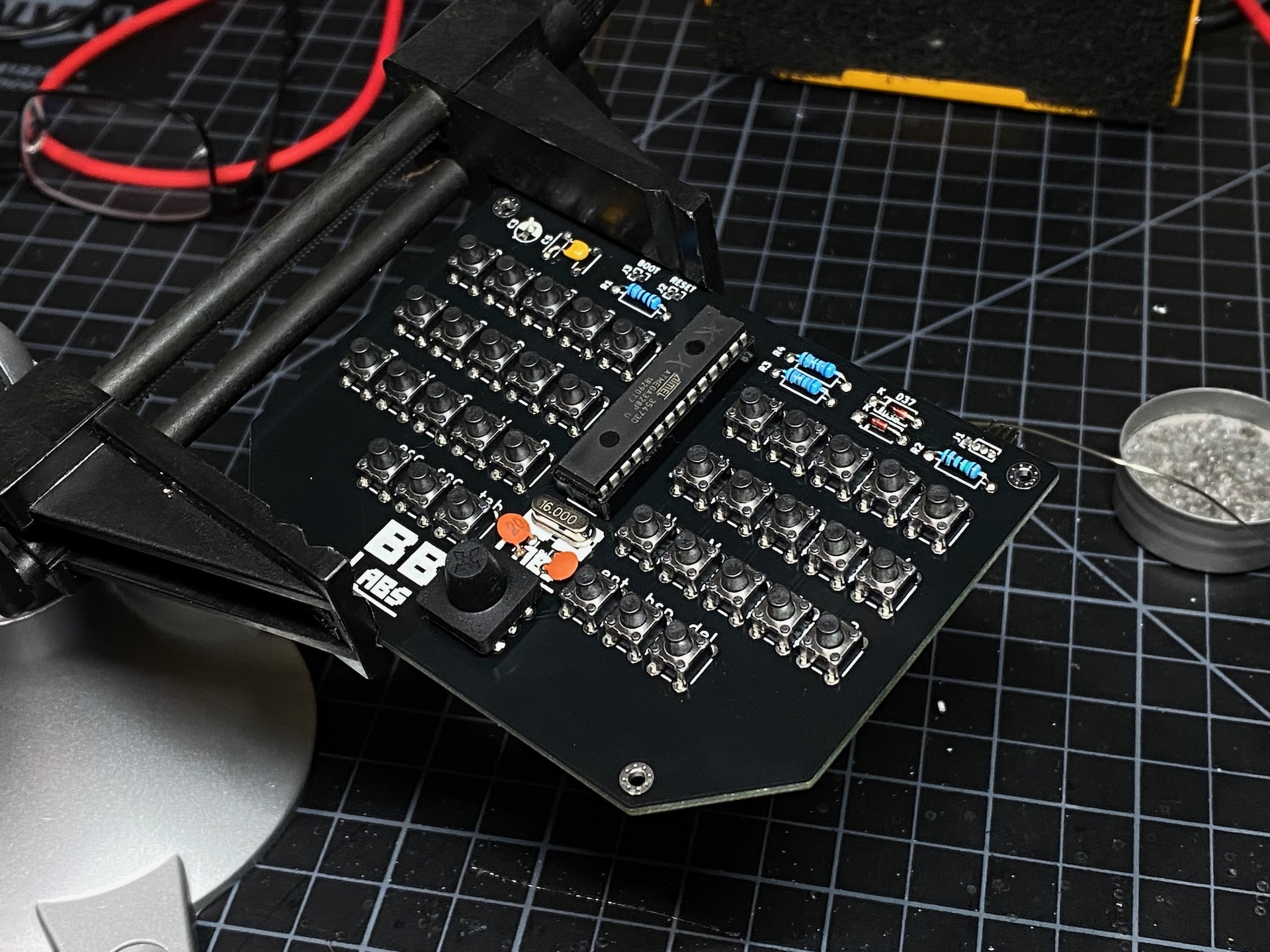
This is actually version 2... for the first one I thought I understood more than I did and left off the 3.6v zener diodes on the USB data lines. BTW, USB actually uses 3.6v signals! Who knew? I didn't know, so I thought the zeners were for overvoltage protection... They are not and many USB hubs/controllers won't work with 5v signal lines. So, you need those if you are using a 5v MCU.
Here's a good place to thank PCBWay for covering the cost of these boards. Liam reached out to me after seeing the Framedeck project with it's custom keyboard/trackball PCB and asked me to give PCBWay a try with my next project. I did, and they gave me a coupon to cover the cost, which was right nice of them. The PCB's are not overly complicated, but the pricing was in line with other vendors, they arrived quickly, looked nice and clean and were fabbed to spec. Overall, a nice experience and I'll definitely consider them again in the future.
So after two revisions, everything worked and it looks nice and tidy with the 1mm top PCB to cover the guts and present nice legends.
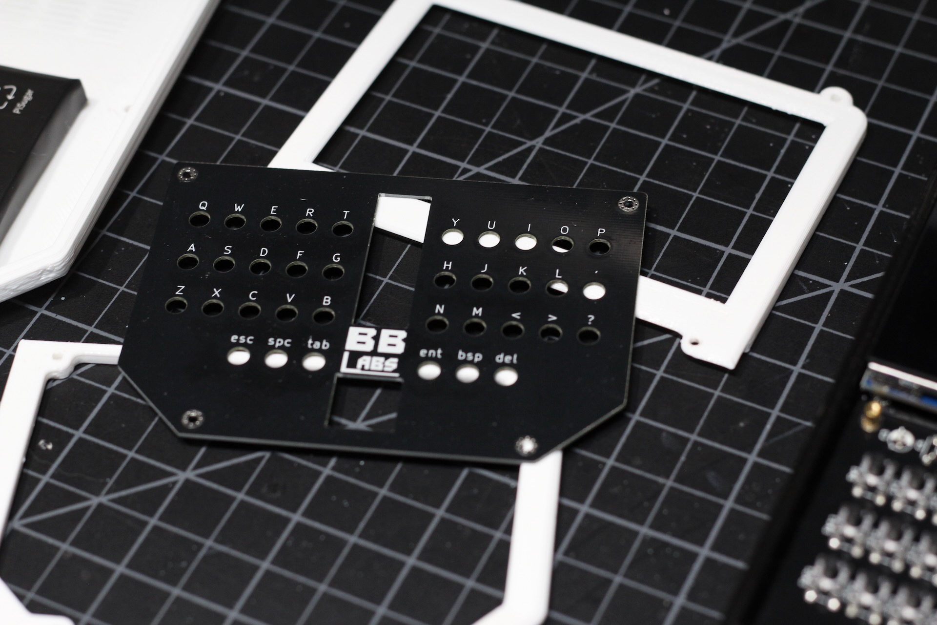
This little bad-boy runs Raspberry Pi OS, a Debian derivitive, and I use i3 as my window manager. This is a great tiling window manager that I run on all my linux systems, but it's particularly well suited for resource limited machines as it's very light weight. It's also very keyboard friendly, which helps as this unit does not have a great pointing device. The touchscreen works okay for some things, and the Miryoku layout has support for mouse keys on a layer (which can be used with hjkl or the directional button) , but I prefer keyboard interaction where possible.
i3 does have a good number of multi-key combos to get stuff done, and these are tricky with just two thumbs. It's possible to get another finger in the mix and still hold on, but I ended up using the directional button for a lot of the multi-key directional bits like focus left/right/up/down, resizing windows, or switching desktops. The directions are mapped to mod-h,j,k,l which will change window focus by default. I can combine this shift to move windows. If I hold down the center directional button, the four directions change between four desktops, and I can combine this with shift to move a window to a specific desktop!
There are some other less common combos (like defining vertical/horizontal splits) that can always be accessed using the actual key combos
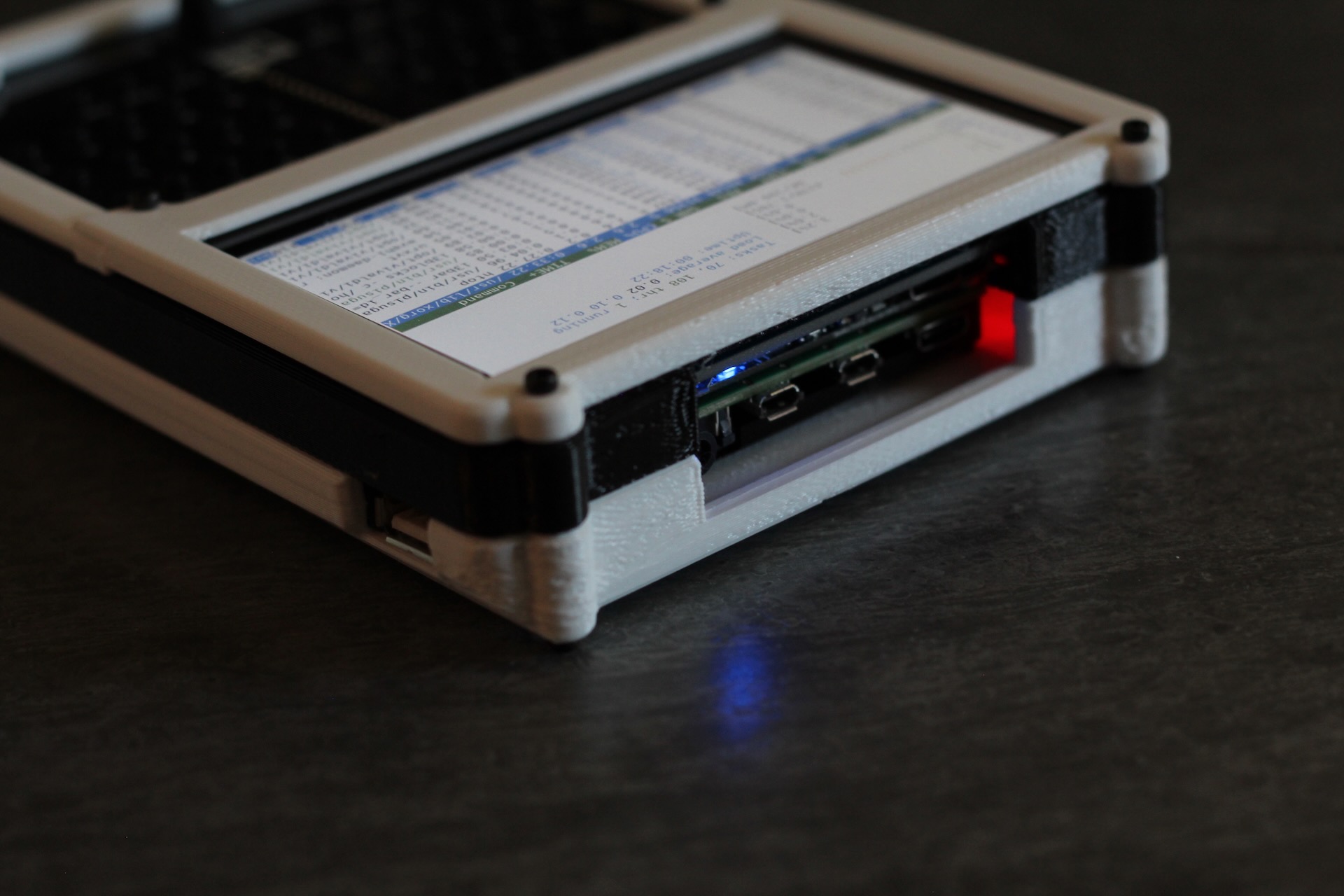
Here's a photo of the back of the unit showing the HDMI, audio output, and charging port of the PiSugar. To the left (in the photo, right side of the unit) is the one available USB port on the RPI 4. To make the whole thing thinner, I removed the ethernet jack and double USB ports. One of the usb pinouts is run internally to talk to the keyboard, and I put a single-high USB jack on the other for external connections.
If you'd like to learn more about how this was all put together check these links below:
Copyright (c) 2022 Richard Sutherland. All rights reserved.
All files are licensed under MIT license see the LICENSE for more information.

| Qty | Value | Footprint | References |
|---|---|---|---|
| 36 | D | Diode_SMD:D_SOD-123 | D1, D2, D10, D11, D12, D13, D14, D15, D16, D17, D18, D19, D20, D21, D22, D23 +20 |
| 36 | SW_Push_Dual | RSU:SW_PUSH_6mm_with_hole | SW1, SW2, SW10, SW11, SW12, SW13, SW14, SW15, SW16, SW17, SW18, SW19, SW20, SW21, SW22, SW23 +20 |
| 4 | Hole_Pad | Horizon:Mount_M2 | H1, H2, H3, H4 |
| 2 | 100n | Capacitor_THT:C_Disc_D4.3mm_W1.9mm_P5.00mm | C4, C5 |
| 2 | 22p | Capacitor_THT:C_Disc_D3.0mm_W2.0mm_P2.50mm | C1, C2 |
| 2 | 75R | Resistor_THT:R_Axial_DIN0207_L6.3mm_D2.5mm_P10.16mm_Horizontal | R3, R4 |
| 2 | D_Zener | Diode_THT:D_A-405_P7.62mm_Horizontal | D37, D38 |
| 1 | 1.5k | Resistor_THT:R_Axial_DIN0207_L6.3mm_D2.5mm_P10.16mm_Horizontal | R2 |
| 1 | 10k | Resistor_THT:R_Axial_DIN0207_L6.3mm_D2.5mm_P10.16mm_Horizontal | R1 |
| 1 | 16mhz | Crystal:Crystal_HC18-U_Vertical | Y1 |
| 1 | 4.7u | Capacitor_THT:CP_Radial_D4.0mm_P1.50mm | C3 |
| 1 | 5-way_switch | RSU:switch_5way | SW39 |
| 1 | ATmega328-PU | Package_DIP:DIP-28_W7.62mm | U1 |
| 1 | BOOT | Connector_PinHeader_1.27mm:PinHeader_1x02_P1.27mm_Vertical | J3 |
| 1 | LOGO1 | RSU_Graphics:bblabs_logo_sml | LOGO1 |
| 1 | PCBLogo | RSU_Graphics:bblabs_logo_sml | PCBLogo |
| 1 | RESET | Connector_PinHeader_1.27mm:PinHeader_1x02_P1.27mm_Vertical | J2 |
| 1 | USB_Connector | Connector_PinHeader_1.27mm:PinHeader_1x04_P1.27mm_Vertical | J1 |
It measures 104.9 × 75.2 mm and has 2 copper layers, 1.6 mm thick.
95 parts, built around the ATMEGA328-PU. The full list of its parts is on this page, with links to each part's symbol and footprint where PCBKit's library has them.
From the brickbots/HandiPi repository on GitHub, at the commit this page was made from: the board is kicad/handipi_kb/handipi_kb.kicad_pcb and its schematic kicad/handipi_kb/handipi_kb.kicad_sch. PCBKit opens the board in the browser, with nothing to install.
Its repository publishes it under the MIT licence: you may reuse it on that licence's terms (keep the author's notice, and for a copyleft licence share your changes alike).


peej/lumberjack-keyboard
5x12 ortholinear through-hole component keyboard PCB for standard 60% cases

peterheinrich/InternetOverSpaghetti
Transmitting IP packages over a pair of spaghetti thus demonstrating how media independent IP really is.


ThomasVDD/SmartSupply
SmartSupply is a digital battery powered lab powersupply. It is Arduino compatible and can be controlled via PC over USB.