
2 layers104.9 × 75.2 mm

 peej/lumberjack-keyboard403
5x12 ortholinear through-hole component keyboard PCB for standard 60% cases
Lumberjack is an open-source printed circuit board by peej, from the peej/lumberjack-keyboard repository on GitHub, published under the MIT licence. It is a 2-layer board of 284.7 × 94.2 mm with 165 parts on 95 nets, routed with 1,005 tracks and 16 vias.
It is built around the ATMEGA328-PU. Its parts include 64 diodes, 8 resistors, 5 capacitors, 5 connectors and 2 switches. It belongs with the keyboards and input boards and the AVR (ATmega, ATtiny) boards of this library.
Lumberjack is a split 5x12 ortholinear keyboard PCB using through-hole components only.
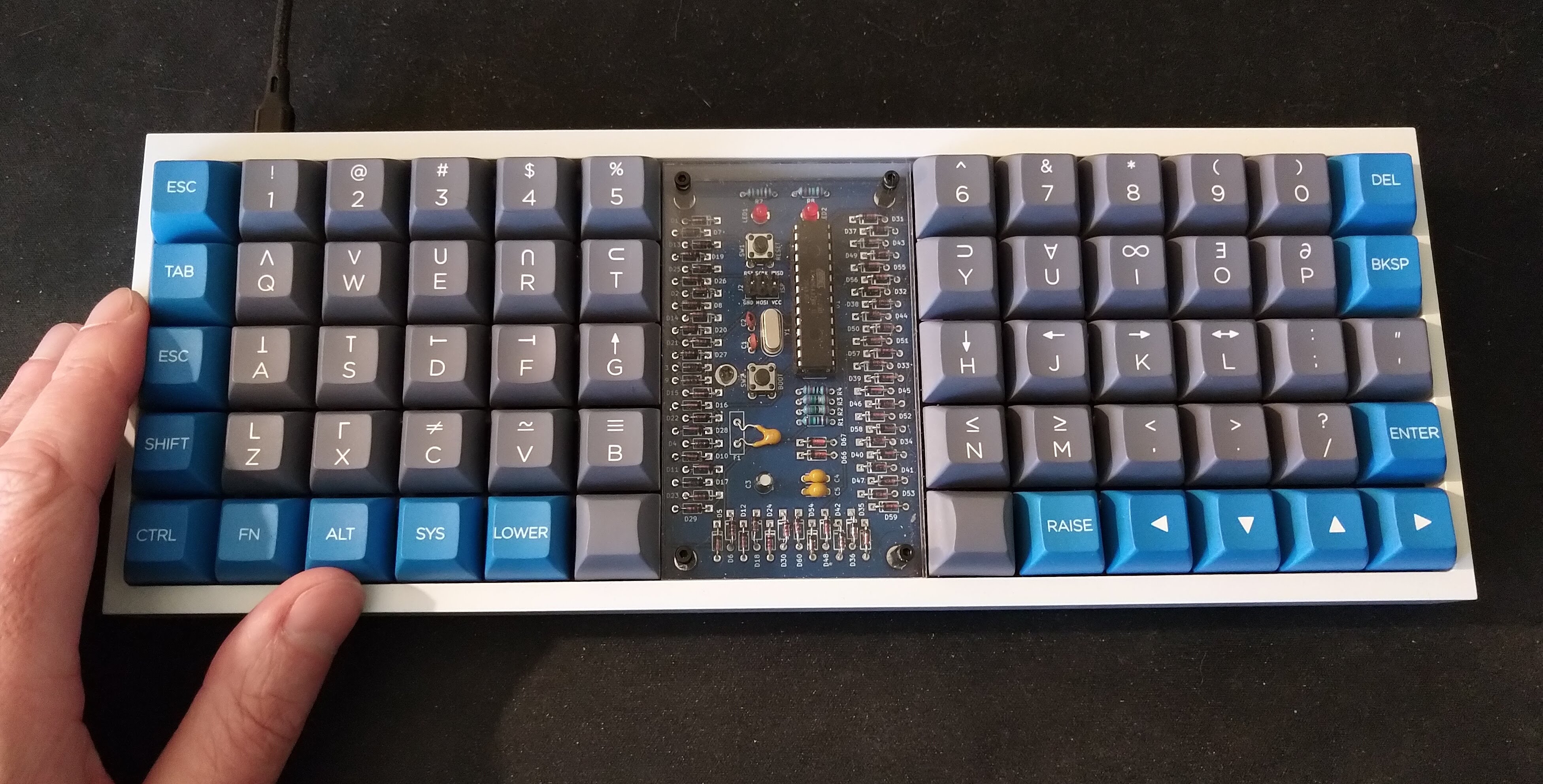
The goal of this project is to build an all through-hole component ortholinear PCB that fits in a standard 60% tray mount case.
Inspired by the Plaid keyboard.
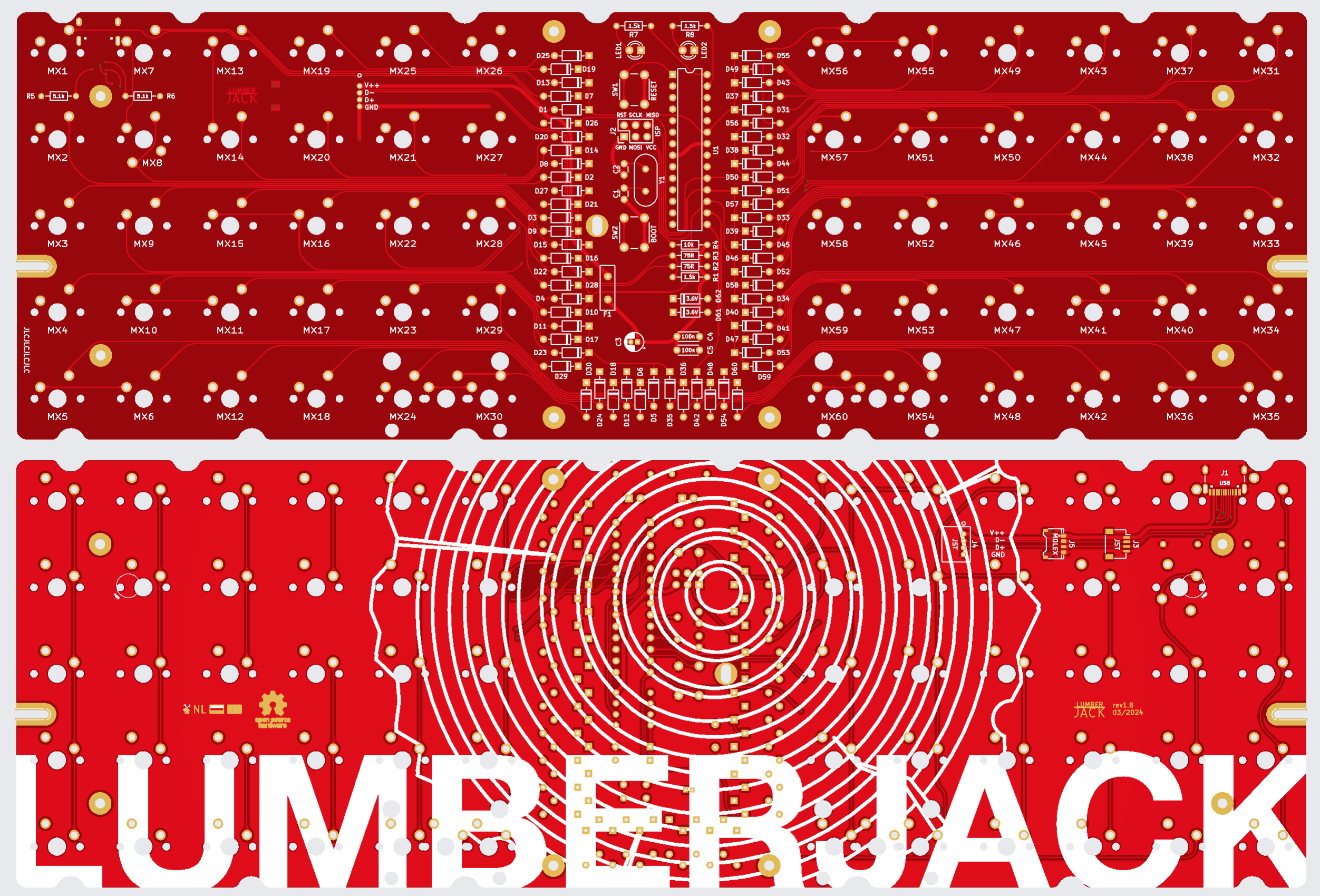
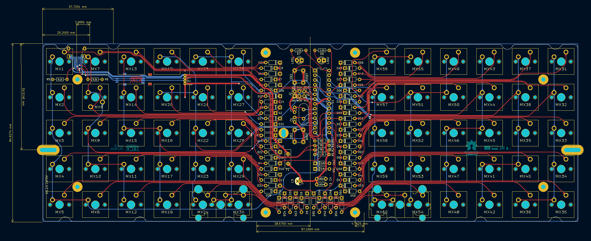
See the Bill of materials for a detailed list of the required parts.
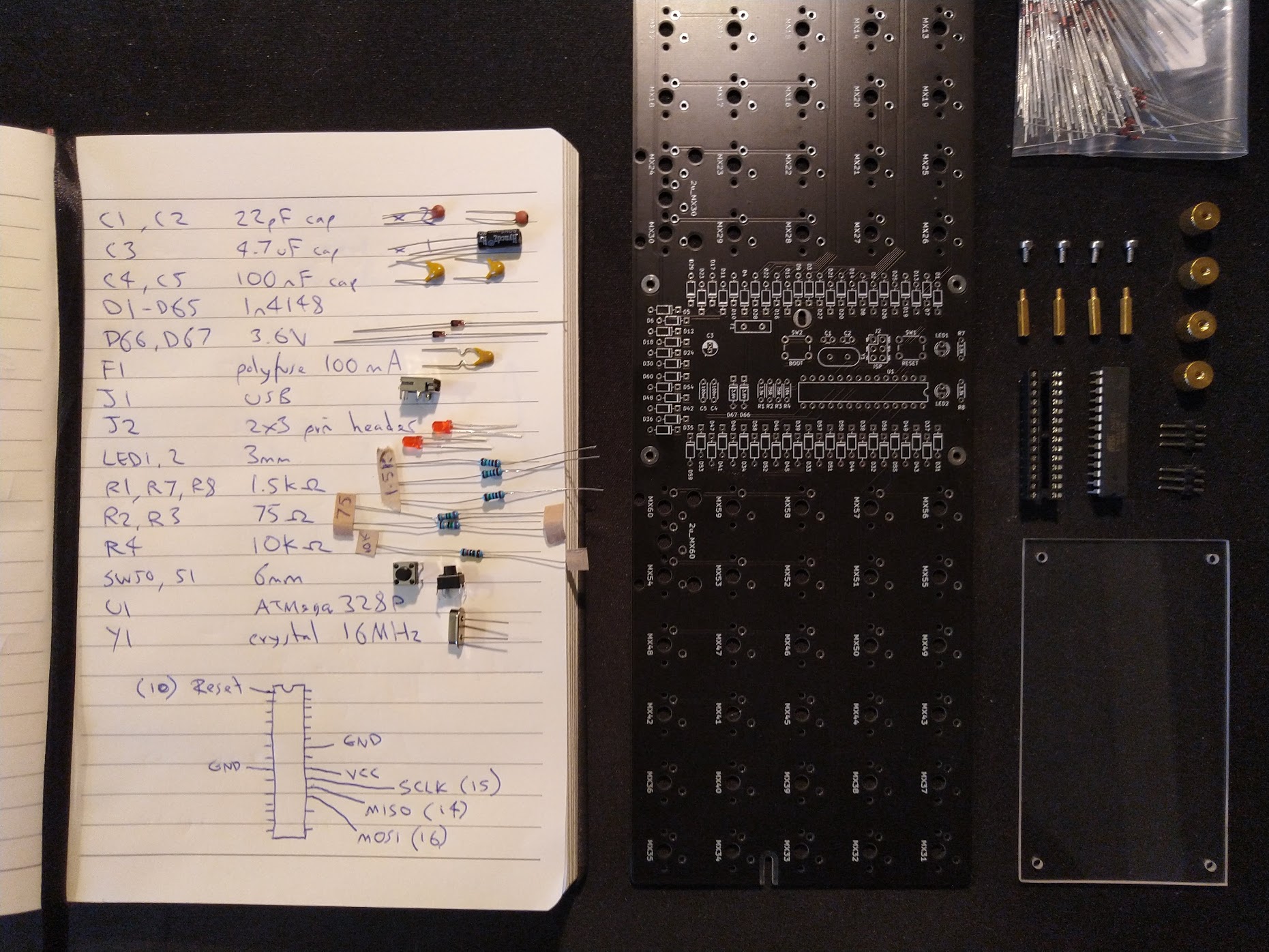
PCBs can be manufactuered by a variety of online PCB fabricators. You can use PCBShopper to search for the best price.
The zip file in the gerber directory contains the gerber files your fabricator will need to make the PCB.
When uploading the gerber zip files, use the default PCB settings.
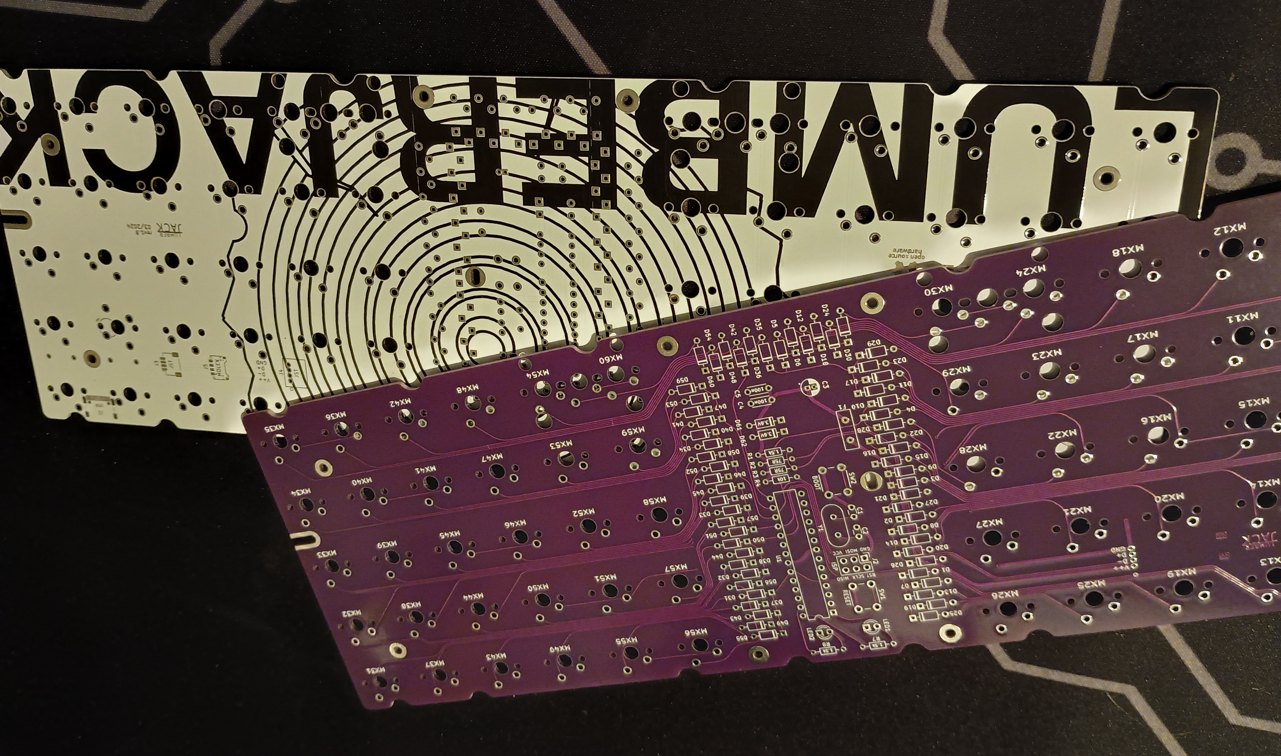
If you want to use a plate, there are gerbers for FR4 plates. For the split plate, you will need two plates, one for each half of the keyboard.
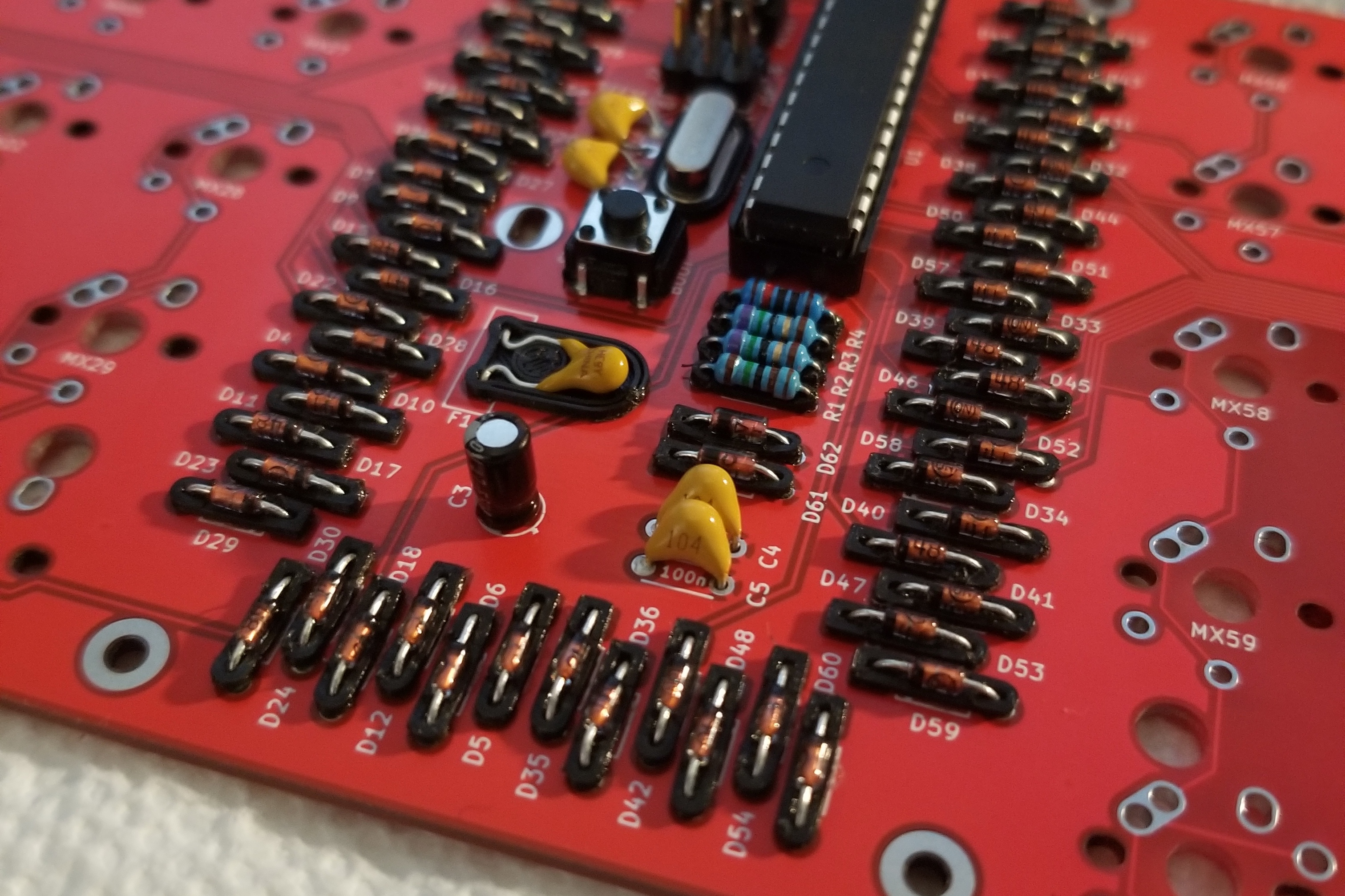
Solder all the components onto the top side of the PCB except the USB connector which should be on the back of the board. Leave the larger components until last so that the board will lie flat upsidedown while you solder the resistors and capacitors.
Take care to put the correct value resistors and capacitors in the correct places, the values are written on the silkmask along with the component reference. If you are unsure about the value of a resistor, check it with a multimeter.
Ensure that polarised components (diodes, LEDs, electrolytic capacitor (C3), IC socket) are in the correct orientation. The square pad is for the negative side of the component; for a diode this means the side with the black stripe; for LEDs and C3 the short leg is the cathode and goes in the square pad.
See the build guide for more information.
Have questions or need help, reach out via our Discord server where you will find many helpful Lumberjack owners.
Firmware is available in the QMK repository under the name peej/lumberjack.
Follow the QMK firmware instructions to build and flash the firmware.
To put the board into bootloader mode so it is ready to recieve firmware, press and hold the BOOT button (SW2) while pressing and releasing the RESET button (SW1). The board will now be detected as an USBasp device and can have the firmware flashed via the USB port.
Pressing the RESET button (SW1) on its own will restart the microprocessor. Once flashed with firmware it is neccessary to reset the keyboard so as to return control to the new firmware.
Note that due to the BOOT button (SW2) sharing a pin with column 3, when pressed the keys in that column will also activate. This is expected behavour but can be a little annoying or confusing if you are not expecting it.
There is a VIA compatible firmware available in QMK. With this firmware flashed, the board will be automatically recognised by VIA when you plug it in.
If you have a "raw" chip without a bootloader, you will need to compile and flash the bootloader onto the chip via another device. See the build guide for more information.
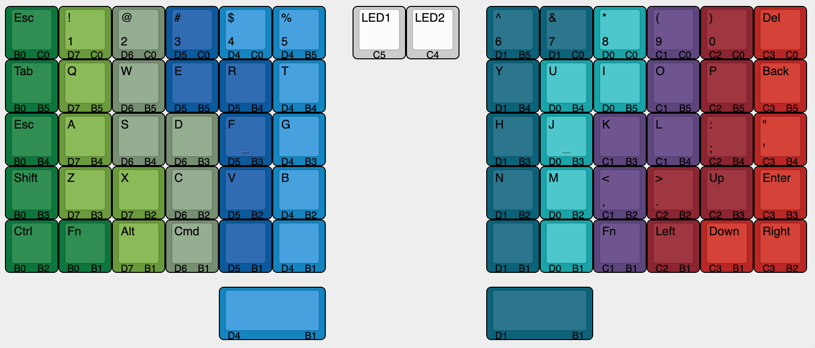
If you are building your own firmware, the following matrix information will be useful to you:
| Configuration | Value |
|---|---|
| MATRIX_ROWS | 6 |
| MATRIX_COLS | 10 |
| MATRIX_ROW_PINS | C0, B5, B4, B3, B2, B1 |
| MATRIX_COL_PINS | B0, D7, D6, D5, D4, D1, D0, C1, C2, C3 |
| DIODE_DIRECTION | COL2ROW |
Due to the limited pin number of the ATMEGA328P, the PCB uses a 6 by 10 matrix (16 pins) instead of a 5 by 12 matrix (17 pins), this makes organising the matrix in your firmware slightly more complicated. The image below shows pins for each key.
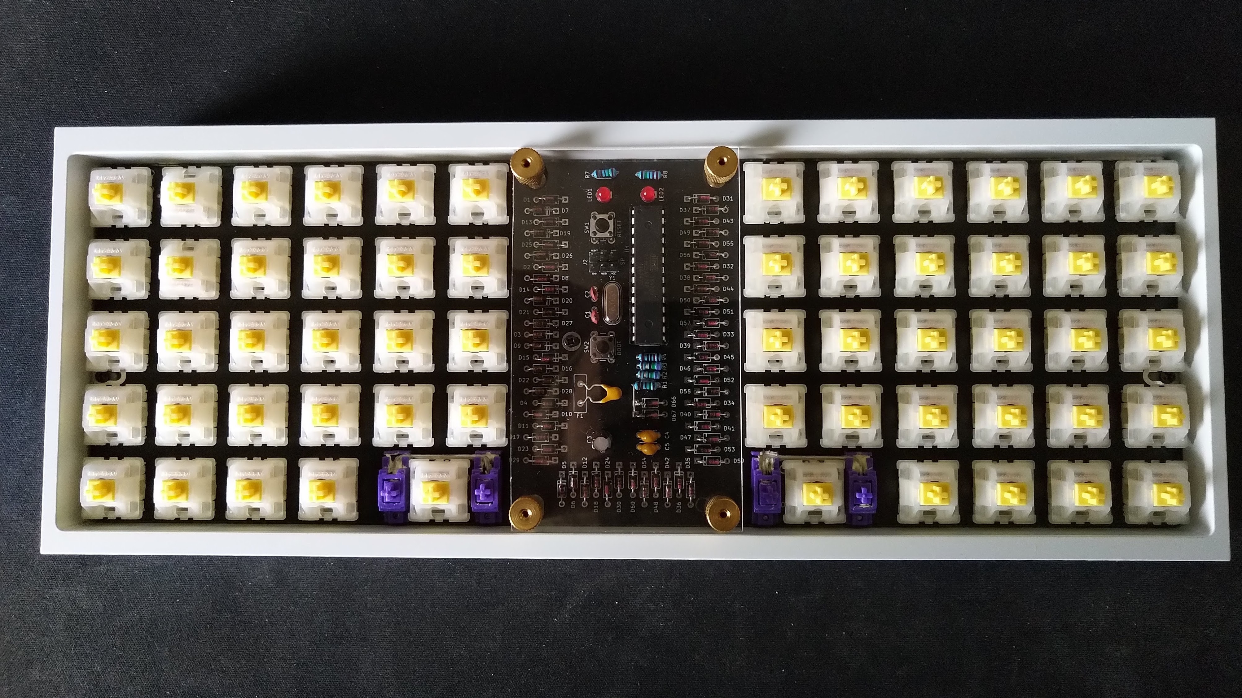
Cut a piece of 2mm thick acrylic to size (95x57mm) and drill 4 m2 holes in the corners for the standoffs. Use the PCB or cover.dxf as a guide for the hole positions, you can also use cover.dxf for laser cutting the correct size acrylic.
Affix the 4 standoffs to the PCB with screws from underneath the PCB. Use the remaining 4 screws to attach the acrylic to the top of the standoffs.
Want to give your components the comfort they need, right?
These 3d printable cradles for your electornic components provided by SuPaSeM#3659 (discord) will hold things in place, keep them neat and tidy, and cradle your components like a baby.
| Qty | Value | Footprint | References |
|---|---|---|---|
| 60 | 1N4148 | Diode_THT:D_DO-35_SOD27_P7.62mm_Horizontal | D1, D2, D10, D11, D12, D13, D14, D15, D16, D17, D18, D19, D20, D21, D22, D23 +44 |
| 59 | SW_Push | lumberjack:MX | MX1, MX2, MX10, MX11, MX12, MX13, MX14, MX15, MX16, MX17, MX18, MX19, MX20, MX21, MX22, MX23 +43 |
| 8 | M2 | lumberjack:MountingHole_M2 | H1, H2, H3, H4, H8, H9, H10, H11 |
| 3 | 1.5k | Resistor_THT:R_Axial_DIN0204_L3.6mm_D1.6mm_P7.62mm_Horizontal | R1, R7, R8 |
| 3 | M2 | lumberjack:MountingSlot_M2 | H5, H6, H7 |
| 2 | 100n | Capacitor_THT:C_Disc_D4.3mm_W1.9mm_P5.00mm | C4, C5 |
| 2 | 22p | Capacitor_THT:C_Disc_D3.0mm_W1.6mm_P2.50mm | C1, C2 |
| 2 | 3.6V | Diode_THT:D_DO-35_SOD27_P7.62mm_Horizontal | D61, D62 |
| 2 | 5.1k | Resistor_THT:R_Axial_DIN0204_L3.6mm_D1.6mm_P7.62mm_Horizontal | R5, R6 |
| 2 | 75R | Resistor_THT:R_Axial_DIN0204_L3.6mm_D1.6mm_P7.62mm_Horizontal | R2, R3 |
| 2 | SW_Push | lumberjack:MX_PCB_200B | 2u_MX30, 2u_MX60 |
| 1 | 100mA | Fuse:Fuse_Bourns_MF-RHT100 | F1 |
| 1 | 10k | Resistor_THT:R_Axial_DIN0204_L3.6mm_D1.6mm_P7.62mm_Horizontal | R4 |
| 1 | 16MHz | Crystal:Crystal_HC49-4H_Vertical | Y1 |
| 1 | 4.7u | Capacitor_THT:CP_Radial_D4.0mm_P1.50mm | C3 |
| 1 | ATMEGA328-PU | Package_DIP:DIP-28_W7.62mm | U1 |
| 1 | AVR_ISP_6 | Connector_PinHeader_2.54mm:PinHeader_2x03_P2.54mm_Vertical | J2 |
| 1 | BOOT | Button_Switch_THT:SW_PUSH_6mm | SW2 |
| 1 | GREEN | LED_THT:LED_D3.0mm | LED2 |
| 1 | JST | lumberjack:S4B-ZRLFSN | J4 |
| 1 | JST | Connector_JST:JST_SH_SM04B-SRSS-TB_1x04-1MP_P1.00mm_Horizontal | J3 |
| 1 | Molex | lumberjack:PicoEZMate-Reinforced-Lite | J5 |
| 1 | RED | LED_THT:LED_D3.0mm | LED1 |
| 1 | RESET | Button_Switch_THT:SW_PUSH_6mm | SW1 |
| 1 | SW_Push | lumberjack:MX_NTHSTH | MX8 |
| 1 | USB | lumberjack:TYPE-C-31-M-12 | J1 |
The 160 most common of 165 parts.
It measures 284.7 × 94.2 mm and has 2 copper layers, 1.6 mm thick.
165 parts, built around the ATMEGA328-PU. The full list of its parts is on this page, with links to each part's symbol and footprint where PCBKit's library has them.
From the peej/lumberjack-keyboard repository on GitHub, at the commit this page was made from: the board is lumberjack.kicad_pcb and its schematic lumberjack.kicad_sch. PCBKit opens the board in the browser, with nothing to install.
Its repository publishes it under the MIT licence: you may reuse it on that licence's terms (keep the author's notice, and for a copyleft licence share your changes alike).


peterheinrich/InternetOverSpaghetti
Transmitting IP packages over a pair of spaghetti thus demonstrating how media independent IP really is.


ThomasVDD/SmartSupply
SmartSupply is a digital battery powered lab powersupply. It is Arduino compatible and can be controlled via PC over USB.