2 layers44.5 × 46.9 mm
OSO SWAT B1-jig
joeycastillo/Sensor-Watch
A board replacement for the classic Casio F-91W wristwatch
31 parts2.1k

 llegoff/Pi400VGA16
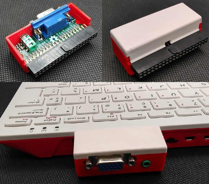
VGA interface for Raspberry pi 400
Pi400VGA is an open-source printed circuit board by llegoff, from the llegoff/Pi400VGA repository on GitHub. It is a 2-layer board of 51 × 20 mm with 31 parts on 47 nets, routed with 234 tracks and 13 vias.
Its parts include 6 resistors, 4 capacitors and 3 connectors. It belongs with the interfaces and adapters boards of this library.
VGA interface for Raspberry Pi 400
:warning: for retrogaming on CRT see Scart/VGA interface : https://github.com/llegoff/Pi400RGB
for pi zero see https://github.com/llegoff/VGA_Zero
buy on ebay :package:
Like VGA666, this pcb uses dpi interface (in mode 3 to free gpio 18 & 19)
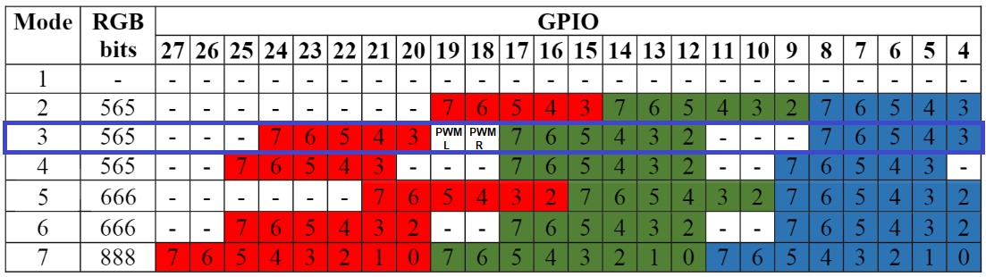
see https://www.raspberrypi.org/documentation/hardware/raspberrypi/dpi/README.md
only the necessary bits of the dpi are redirected to the 40-pin GPIO port, with the 'gpio=2-8,12-17,20-24=a2' line on config.txt
/boot/config.txt
# disable i2c, pin use by h-sync & v-sync
dtparam=i2c_arm=off
# replace dtoverlay=vc4-kms-v3d with
dtoverlay=vc4-fkms-v3d
#DPI config
gpio=2-8,12-17,20-24=a2
dpi_output_format=0x13
enable_dpi_lcd=1
display_default_lcd=1
dpi_group=2
dpi_mode=16
#---------------- dpi_mode line ---------------------
#---> 640x480 60hz    dpi_mode=4
#---> 800x600 60hz    dpi_mode=9
#---> 1024x768 60hz   dpi_mode=16
#---> 1280x768 60hz   dpi_mode=23
#---> 1280x800 60hz   dpi_mode=28
#---> 1280x960 60hz   dpi_mode=32
#---> 1280x1024 60hz  dpi_mode=35
#---> 1360x768 60hz   dpi_mode=39
#---> 1366x768 60hz   dpi_mode=81
#---> 1400x1050 60hz  dpi_mode=42
#---> 1440x900 60hz   dpi_mode=47
#---> 1600x1200 60hz dpi_mode=51Configuration working with vc4-kms-v3d
dtoverlay=vc4-kms-dpi-generic,rgb565-padhi
dtparam=hactive=800,hfp=40,hsync=128,hbp=88
dtparam=vactive=600,vfp=1,vsync=4,vbp=23
dtparam=clock-frequency=40000000
#   Resolution@freq  hactive hfp hsync  hbp vactive vfp vsync vbp  clock-frequency
#VGA   640x480  @60   640     16   96    48   480    10   2    33    25175000
#SVGA  800x600  @60   800     40  128    88   600     1   4    23    40000000
#XGA  1024x768  @60  1024     24  136   160   768     3   6    29    65000000
#VESA 1368x768  @60  1368     72  144   216   768     1   3    23    85860000
#VESA 1280x800  @60  1280     64  136   200   800     1   3    24    83460000
#VESA 1280x1024 @60  1280     48  112   248  1024     1   3    38   108000000
#VESA 1400x1050 @60  1400     88  152   240  1050     1   3    33   122660000
#VESA 1600x1200 @60  1600     64  192   304  1200     1   3    46   162000000
#--- TV -----
#244p (NTSC res)@60   320      4   30    46   240     4   5    14     6400000
#288p (PAL res) @50   384     16   32    40   288     3   2    19     7363200
#480i (NTSC res)@60   640     24   64   104   480     3   6    34    13054080
#576i (PAL res) @50   768     24   72    88   576     6   5    38    14875000
#480p           @60   640     24   96    48   480    11   2    32    25452000
#720p           @60  1280    110   40   220   720     5   5    20    74250000
#1080p          @60  1920     88   44   148  1080     4   5    36   148500000
#more timming on http://tinyvga.com/vga-timing:point_up: this config work only with Raspberry pi OS, not with Recalbox OS or RGB-Pi OS (use rpi-dpidac, who only work with dpi mode 5 & 6)
for RecalboxOS or RGB-Pi OG , see https://github.com/llegoff/Pi400RGB
# replace dtoverlay=vc4-kms-v3d with
dtoverlay=vc4-fkms-v3d
# disable i2c, pin use by h-sync & v-sync
dtparam=i2c_arm=off
gpio=2-8,12-17,20-24=a2
dpi_output_format=0x13
enable_dpi_lcd=1
display_default_lcd=1
dpi_group=2
dpi_mode=87
#hdmi_timings=506 1 8 48 56 240 1 3 10 6 0 0 0 60 0 9600000 1
#hdmi_timings=512 1 16 48 64 288 1 3 5 6 0 0 0 50 0 9600000 1
# Custom 15kHz mode
hdmi_timings=506 1 8 44 52 240 1 6 10 6 0 0 0 60 0 9600000 1
#hdmi_timings=320 1 17 33 34 224 1 14 8 18 0 0 0 60 0 6400000 1
#hdmi_timings=960 0 173 8 0 160 0 40 10 0 0 0 0 60 0 19200000 8
#hdmi_timings=320 1 25 30 30 240 1 9 3 10 0 0 0 60 0 6400000 1
#hdmi_timings=1920 1 52 208 260 240 1 6 10 6 0 0 0 60 0 38400000 1edit /boot/config.txt
find section
[pi4]
temp_soft_limit=70
dtoverlay=vc4-kms-v3d
remplace with
[pi4]
temp_soft_limit=70
dtoverlay=vc4-fkms-v3d
copy content of config-example.txt to /boot/recalbox-user-config.txt
For crt mode , Recalbox 8 use driver rpi-dpidac, not compatible with dpi mode 3
see https://wiki.recalbox.com/en/tutorials/video/crt/crt-screen-dpi-vga666-piscart-rgbpi
on the pi4 and pi400, the dual screen function is supported by the vc4 fkms v3d driver
[pi4]
# Enable DRM VC4 V3D driver on top of the dispmanx display stack
dtoverlay=vc4-fkms-v3d
max_framebuffers=2install freeRDP
sudo apt-get install freerdp2-x11start freeRDP session
xfreerdp /v:<computer name or IP> /u:<user> /d:<domain> /sound:sys:alsa /multimonor
xfreerdp /v:<computer name or IP> /u:<user> /d:<domain> /g:<gateway name or IP> /gu:<gateway user> /gd:<gateway domain> /sound:sys:alsa /multimonaudio interface is connected to gpio 18 & 19 (PWM)
/boot/config.txt
# Enable audio for PiZero(loads snd_bcm2835)
dtoverlay=audremap,pins_18_19
dtparam=audio=on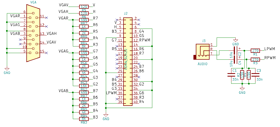
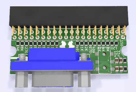
copy content of config-example.txt to /boot/config.txt
rev1
| Qty | Value | Footprint | References |
|---|---|---|---|
| 3 | 1K | Resistors_SMD:R_0805 | RB6, RG6, RR6 |
| 3 | 2K | Resistors_SMD:R_0805 | RB5, RG5, RR5 |
| 3 | 499 | Resistors_SMD:R_0805 | RB7, RG7, RR7 |
| 3 | 4K | Resistors_SMD:R_0805 | RB4, RG4, RR4 |
| 3 | 8K | Resistors_SMD:R_0805 | RB3, RG3, RR3 |
| 2 | 10u | Capacitors_SMD:C_0805 | C2, C4 |
| 2 | 120 | Resistors_SMD:R_0805 | R5, R6 |
| 2 | 150 | Resistors_SMD:R_0805 | R2, R4 |
| 2 | 270 | Resistors_SMD:R_0805 | R1, R3 |
| 2 | 33n | Capacitors_SMD:C_0805 | C1, C3 |
| 1 | 16K | Resistors_SMD:R_0805 | RG2 |
| 1 | AUDIO | _LaurentPerso:jack3.5smd | J3 |
| 1 | CONN_02X20 | Socket_Strips:Socket_Strip_Straight_2x20_Pitch2.54mm | J2 |
| 1 | VGA | _LaurentPerso:DB_15F-VGA | J1 |
The 29 most common of 31 parts.
joeycastillo/Sensor-Watch
A board replacement for the classic Casio F-91W wristwatch

hoglet67/RGBtoHDMI
Bare-metal Raspberry Pi project that provides pixel-perfect sampling of Retro Computer RGB/YUV video and conversion to HDMI

hackclub/OnBoard
💡 Join 1,000 teenagers and make your first PCB with a $100 grant!

openwch/ch32v003
CH32V003 is an ultra-cheap RISC-V MCU with 2KB SRAM, 16KB flash, and up to 18 GPIOs that sells for under $0.10

Luos-io/luos_engine
Open-source and real-time orchestrator for cyber-physical-systems, to easily design, test and deploy embedded applications and digital twins.

BlueAndi/Pixelix
Full RGB LED matrix, based on an ESP32 and WS2812B LEDs or emulated LEDs on TFT.


It measures 51 × 20 mm and has 2 copper layers, 1.6 mm thick.
31 parts. The full list of its parts is on this page, with links to each part's symbol and footprint where PCBKit's library has them.
From the llegoff/Pi400VGA repository on GitHub, at the commit this page was made from: the board is Pi400VGA.kicad_pcb. PCBKit opens the board in the browser, with nothing to install.
Its repository states no licence, so its author keeps all rights: ask llegoff before reusing the design.