2 layers76.4 × 63.3 mm
InfraRedGelUniversalDispenser
abdontroche/InfraRed_Gel_Universal_Dispenser
This project pretends to be a open source device that could help people fighting against the COVID-19.
20 parts5CC0-1.0

 lisasnt/Stepper-motor-testbench
My BSc sperimental thesis
Stepper testbench is an open-source printed circuit board by lisasnt, from the lisasnt/Stepper-motor-testbench repository on GitHub, published under the GPL-3.0 licence. It is a 2-layer board of 67.7 × 78.4 mm with 76 parts on 134 nets, routed with 360 tracks and 134 vias.
It is built around the LM358P and L7805. Its parts include 28 resistors, 19 capacitors, 9 connectors, 8 diodes and 6 ICs. It belongs with the robots and motor control boards of this library.


Step Motor Testbench is a tool made in collaboration with ProM Facility which can be used to measure the maximum power and the maximum torque of a step motor.
Notice that this is a prototype made up to validate the innovative company idea.
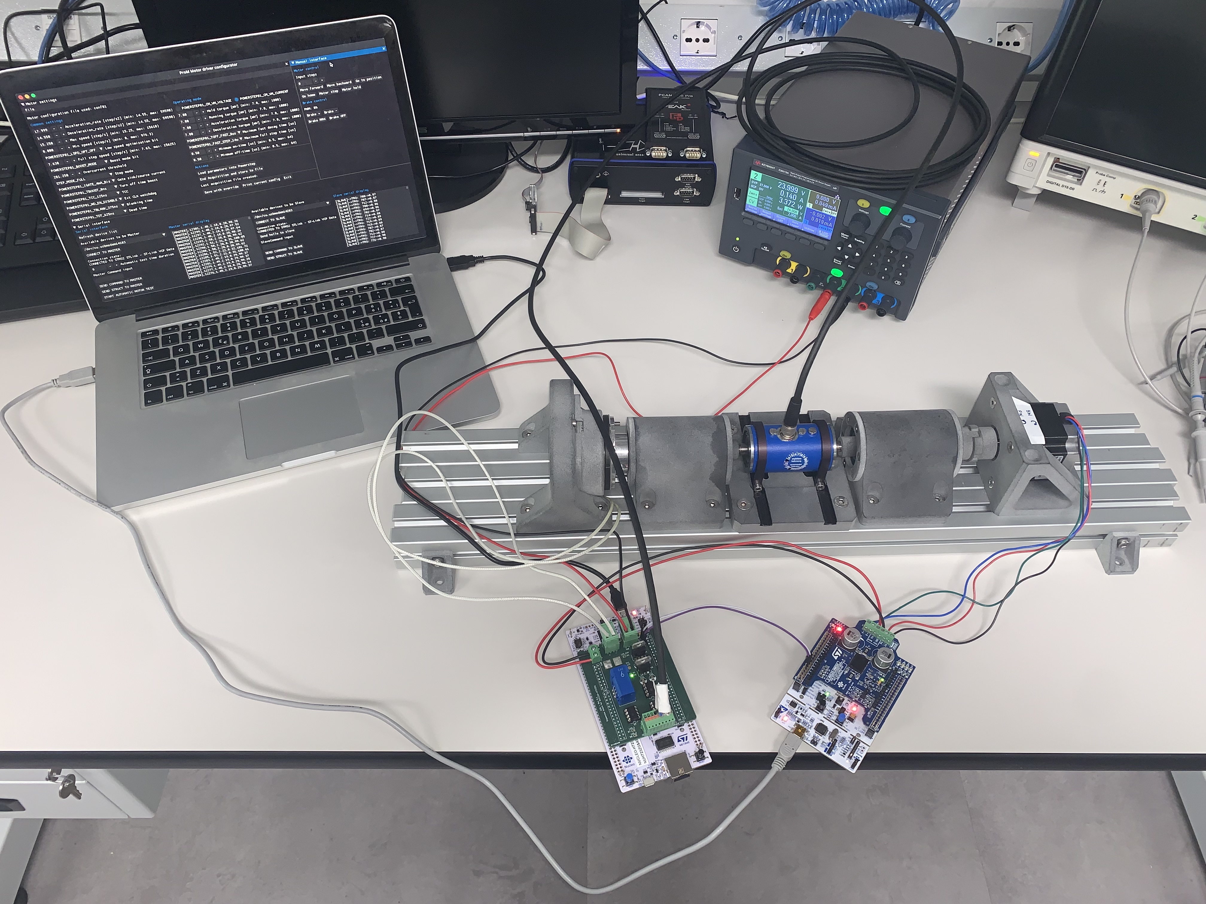
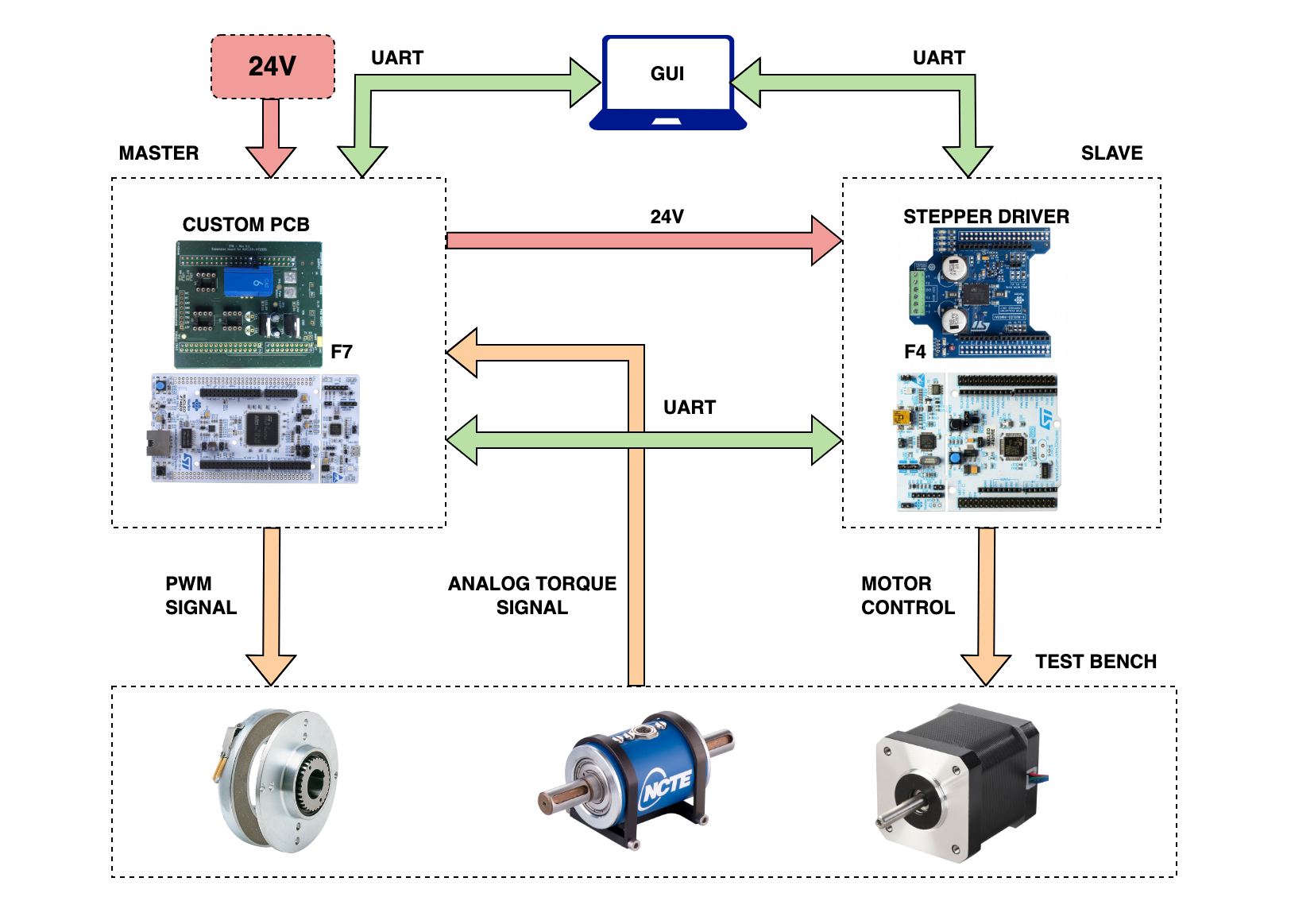
I attended my academic internship at ProM Facility, a company specialised in creating ad-hoc mecha- tronics applications, and here I decided to take part in solving one of their needs. Since several of their applications involve stepper motors, ProM needed to have a stepper testbench to test these devices: in this way, it would be possible to precisely know their behaviour in order to achieve a better final product quality.
This thesis discusses the design and development of a stepper motor testbench prototype sub- section, which includes an expansion board to acquire sensors signals and an Azure RTOS driver unit based on an STM32 microcontroller to physically drive the motor. The system ideated was built from scratch following ProM’s design requirements.
The expansion board represents the hardware part of the project. It is a Printed Circuit Board (PCB) designed with Kicad, an electronic open-source CAD. After being realised, the board was analysed with a thermographic camera to verify the power-on components’ condition state, with an oscilloscope to test the acquired signals’ noise, and with an electromagnetic scanner to measure the electromagnetic compatibility (EMC). On the other hand, the driver unit represents the firmware development of the stepper driver based on STM-Nucleo F4 series board, it is implemented and debugged with the environment offered by STMicroelectronics called STM32-CubeIDE.
The expansion board and the driver unit firmware work properly: they satisfy ProM’s requirements and lay the foundations for future developments of the prototype.
├── 📁 Documentation    -> media and thesis pdf
├── 📁 Firmware         -> slave and master units firmware
├── 📁 GUI              -> graphical user iterface and plot scripts
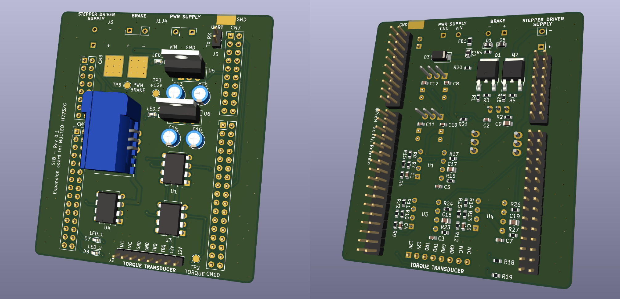
└── 📁 Hardware -> custom master unit expansion board kicad projectThe custom-designed PCB is a shield that can be mounted on top of the main board. It allows for the acquisition of current, voltage, and torque signals while controlling the electromagnetic brake, ensuring proper power management and protection.
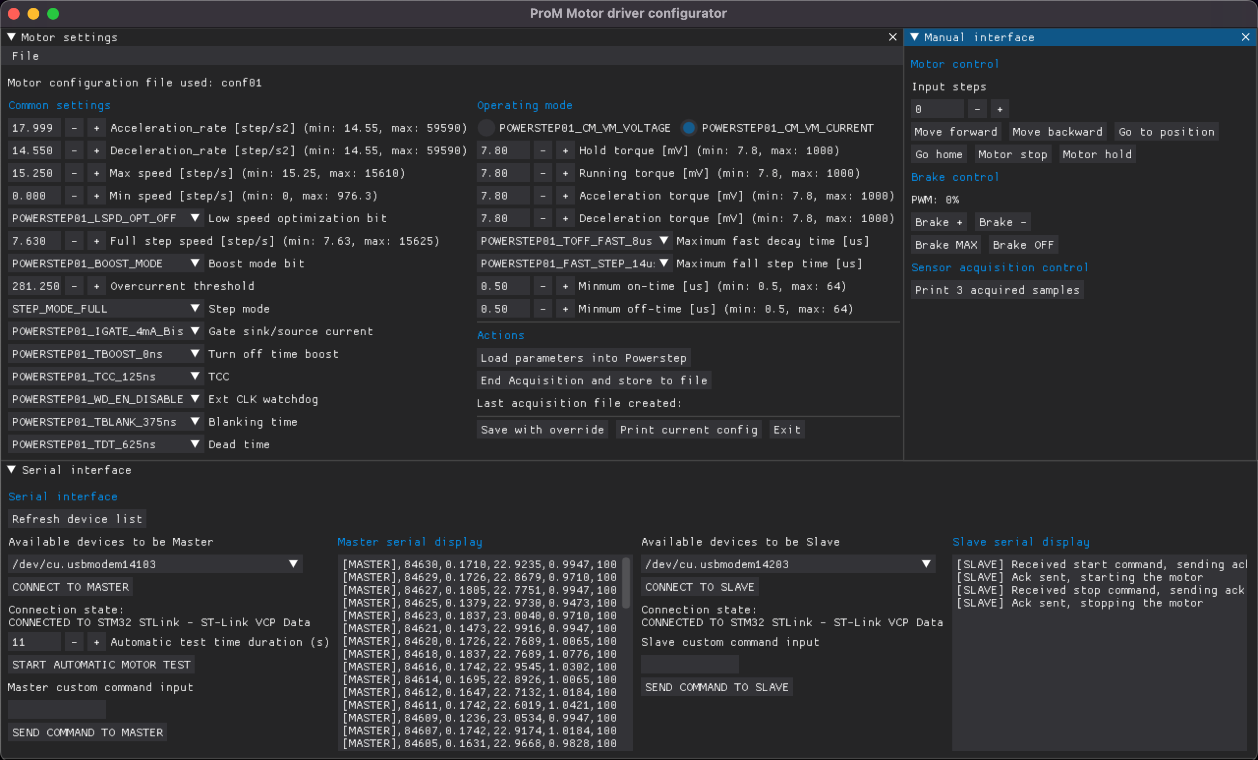
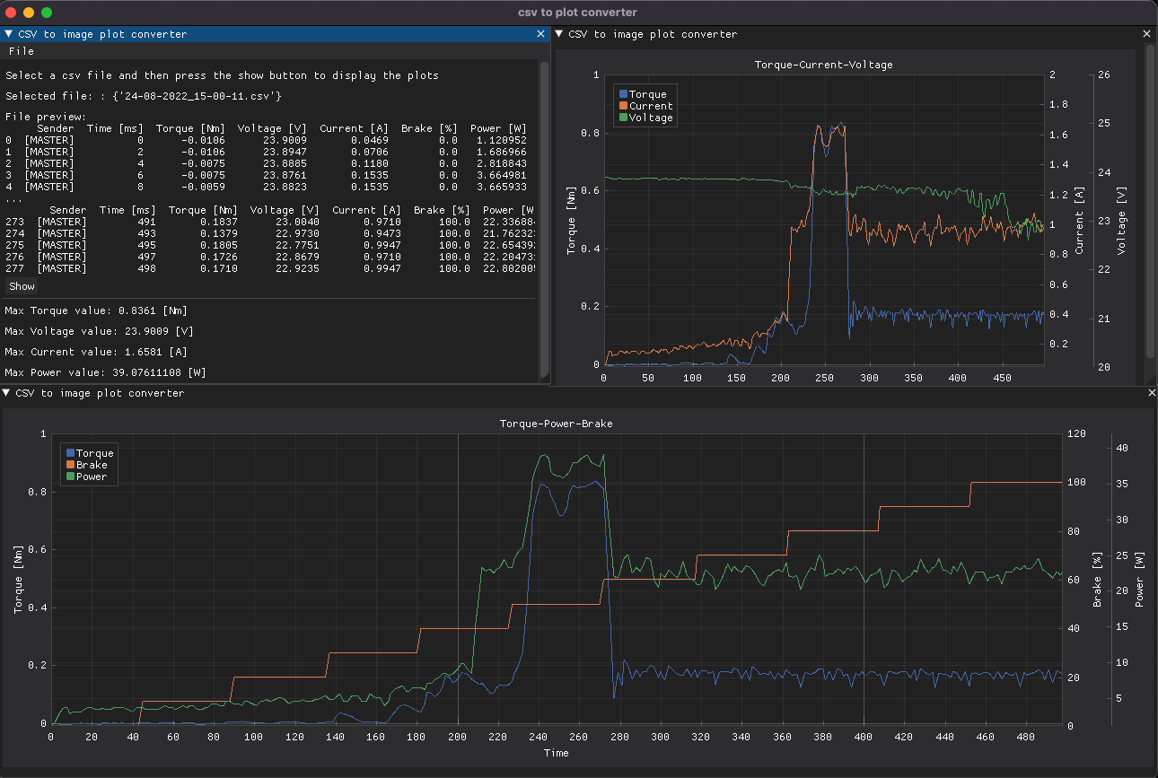
The GUI is made up of two main windows: the first one is used to control the motor driver parameters, to test the motor under load, to communicate with both units using serial communication and to save the acquired data into a csv file. The second one is used to plot the acquired data into some.
The second one is used to read the sensors values and to plot the acquired data in a dynamic way.
| Qty | Value | Footprint | References |
|---|---|---|---|
| 6 | 0.1u | Capacitor_SMD:C_0603_1608Metric | C2, C3, C5, C7, C11, C12 |
| 6 | R | Resistor_SMD:R_0603_1608Metric | R16, R17, R23, R24, R26, R27 |
| 5 | 0 | Resistor_SMD:R_0603_1608Metric | R2, R4, R15, R22, R25 |
| 5 | 10k | Resistor_SMD:R_0603_1608Metric | R1, R6, R9, R12, R28 |
| 3 | 100n | Capacitor_SMD:C_0603_1608Metric | C1, C4, C6 |
| 3 | 620k | Resistor_SMD:R_0603_1608Metric | R8, R11, R13 |
| 3 | C | Capacitor_SMD:C_0805_2012Metric | C17, C18, C19 |
| 3 | DIODE | Diode_SMD:D_0805_2012Metric | D1, D2, D5 |
| 3 | LM358P | Package_DIP:DIP-8_W7.62mm | U1, U3, U4 |
| 2 | 0.1u_DNP | Capacitor_THT:CP_Radial_D5.0mm_P2.50mm | C14, C16 |
| 2 | 0.33u | Capacitor_SMD:C_0603_1608Metric | C8, C10 |
| 2 | 0.33u_DNP | Capacitor_THT:CP_Radial_D5.0mm_P2.50mm | C13, C15 |
| 2 | 330k | Resistor_SMD:R_0603_1608Metric | R7, R10 |
| 2 | 47 | Resistor_SMD:R_0603_1608Metric | R3, R5 |
| 2 | LED | LED_SMD:LED_0603_1608Metric | D7, D8 |
| 2 | Q_NMOS_DGS | Package_TO_SOT_SMD:TO-252-2 | Q1, Q2 |
| 1 | 100k | Resistor_SMD:R_0603_1608Metric | R14 |
| 1 | 12V | TestPoint:TestPoint_Pad_D2.0mm | TP3 |
| 1 | 1k | Resistor_SMD:R_0603_1608Metric | R21 |
| 1 | 330 | Resistor_SMD:R_0603_1608Metric | R19 |
| 1 | 510 | Resistor_SMD:R_0603_1608Metric | R18 |
| 1 | 5k1 | Resistor_SMD:R_0603_1608Metric | R20 |
| 1 | BRAKE | TestPoint:TestPoint_Pad_D2.0mm | TP5 |
| 1 | Brake connector | Connector_PinHeader_2.54mm:PinHeader_1x02_P2.54mm_Vertical | J1 |
| 1 | Conn_01x02 | Connector_PinHeader_2.54mm:PinHeader_1x02_P2.54mm_Vertical | J4 |
| 1 | Conn_01x08 | Connector_PinHeader_2.54mm:PinHeader_1x08_P2.54mm_Vertical | J2 |
| 1 | Conn_02x08_Odd_Even | Connector_PinHeader_2.54mm:PinHeader_2x08_P2.54mm_Vertical | CN8 |
| 1 | Conn_02x10_Odd_Even | Connector_PinHeader_2.54mm:PinHeader_2x10_P2.54mm_Vertical | CN7 |
| 1 | Conn_02x15_Odd_Even | Connector_PinHeader_2.54mm:PinHeader_2x15_P2.54mm_Vertical | CN9 |
| 1 | Conn_02x17_Odd_Even | Connector_PinHeader_2.54mm:PinHeader_2x17_P2.54mm_Vertical | CN10 |
| 1 | DNP | Capacitor_SMD:C_0805_2012Metric | C9 |
| 1 | D_Zener | Diode_SMD:D_SMA | D3 |
| 1 | FerriteBead | Resistor_SMD:R_0805_2012Metric | FB1 |
| 1 | L7805 | Package_TO_SOT_THT:TO-220-3_Vertical | U6 |
| 1 | LED_GREEN | LED_SMD:LED_0603_1608Metric | D6 |
| 1 | LED_RED | LED_SMD:LED_0603_1608Metric | D4 |
| 1 | LEM-CAS-6NP | Sensing lib:LEM-CAS-6-NP | U2 |
| 1 | LM7812_TO220 | Package_TO_SOT_THT:TO-220-3_Vertical | U5 |
| 1 | Stepper supply | Connector_PinHeader_2.54mm:PinHeader_1x02_P2.54mm_Vertical | J6 |
| 1 | TORQUE | TestPoint:TestPoint_Pad_D2.0mm | TP2 |
| 1 | UART Connector | Connector_PinHeader_2.54mm:PinHeader_1x02_P2.54mm_Vertical | J5 |
It measures 67.7 × 78.4 mm and has 2 copper layers, 1.6 mm thick.
76 parts, built around the LM358P and L7805. The full list of its parts is on this page, with links to each part's symbol and footprint where PCBKit's library has them.
From the lisasnt/Stepper-motor-testbench repository on GitHub, at the commit this page was made from: the board is Hardware/kicad-project/stepper_testbench.kicad_pcb and its schematic Hardware/kicad-project/connectors.kicad_sch. PCBKit opens the board in the browser, with nothing to install.
Its repository publishes it under the GPL-3.0 licence: you may reuse it on that licence's terms (keep the author's notice, and for a copyleft licence share your changes alike).
abdontroche/InfraRed_Gel_Universal_Dispenser
This project pretends to be a open source device that could help people fighting against the COVID-19.

igorzab-stud/wanptek_encoder
Digital front-panel mod for Wanptek DC power supplies — replaces analog potentiometers with dual rotary encoders, MCP4725 DACs, and an OLED display.

ansh1113/e-bike-conversion-kit
A 4-layer PCB-based e-bike conversion kit featuring an STM32-based VESC ESC, power management circuits, wireless throttle, GSM, GPS, and more.


UAA-F14/PCBs-Design
Power electronics PCB coursework — SCR controller, buck converter, Class D amplifier, DC-AC inverter, and a protected power supply Resources

asliwaa/ECG-Simulator
A custom hardware ECG/EKG simulator built with the XIAO ESP32-C6 and an MCP4725 DAC, designed to generate physiologically accurate heart signals.


IKGB105/PCBs-POWER-ELECTRONICS
Power electronics PCB coursework — SCR controller, buck converter, Class D amplifier, DC-AC inverter, and a protected power supply Resources