

2 layers75.5 × 71 mm

 Linoprit/ThetaMon3
Measures temperatures with several DS1820 sensors and controlls a heater.
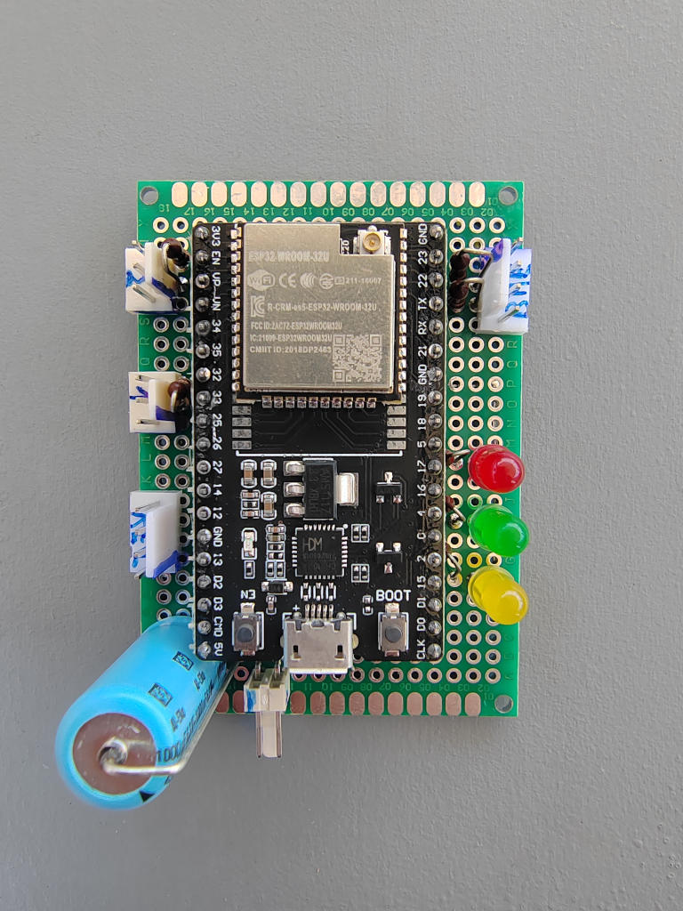
ThetaProbe is an open-source printed circuit board by Linoprit, from the Linoprit/ThetaMon3 repository on GitHub, published under the GPL-3.0 licence. It is a 2-layer board of 83.8 × 52.1 mm with 15 parts on 38 nets, routed with 102 tracks and 0 vias.
It is built around the ESP32-DEVKITC-VE and BME280. Its parts include 7 connectors, 6 resistors, 1 capacitor and 1 IC. It belongs with the home automation and IoT and sensors and measurement boards and the ESP32 boards of this library.
ThetaMon3 is based on an ESP32 controller, which reads a bunch of sensors and sends the results to a MQTT-Broker, like Mosquitto. I use three probes, together with my Home Assistant installation to control the temperature in remote buildings.
Why two OneWire-channels?
I simply had the problem that in the workshop the location of the probe was in the middle of the sensor chain. Unfortunately, it was not possible to place it at one end or the other of the sensor chain.
To understand what ThetaMon does and what it is meant for, we take a look at where the idea comes from.
My wife owns really a lot of pot-plants. These must be kept in a warmer place during the winter time, so we bring them into the garages. Unfortunately, on some days the outside temperatures could drop so low, that even in the garage the plants will die. Of course you use an electric heater, but the control of such devices is not particularly precise. So the idea came up to build a system, that measures at different places in the room, to bring more insight how the heat is distributed and which places are save. Above that, to provide a finer regulation of the heating.
I put together the first version of ThetaMon, based on STM32F103 controllers, it consisted of two satellites and a base-station. The communication was done with NRF24 radios, which are long range capable (more or less...). The base-station was connected to an orange-pi which ran an apache webserver installation and hosted a page to show the graphs of all sensors for the last 24 hours. One very crucial point was, that the satellites work independently. If the connection to the base broke, they must have benn capable to do the regulation. This means, that every node in the system has to keep a table with all relevant temperature-thresholds.
This system ran fine for some years, but I wanted more flexibility and insight, if things went wrong. Sometimes temperature sensors failed, due to connector problems, or the NRF24 modules failed. ThetaMon2 took a very long time to develop, and it became very complex. For example I needed an EEPROM with some kind of file-system to store the sensor tables. The html-generation was done by own code on the used Banana-Pi. Finaly it worked and it was used for one year.
In winter 2023 I took the time to try, if ESP32 with external antenna could keep a stable connection to the Wlan. And yes, it did! Also I looked for some different possibility to do the development and found, that PlatformIO is so much powerfull. Then, a colleague showed me what he does with home automation and I came up to use Home Assistant as dashboard solution. ThetaMon3 took only a half year of development, not only because large parts of code from TM2 have been overtaken, it turned out that PlatformIO absolutely speeds up things.
Refer to: SettingUpThetaMonProbe.
You need a working Visual Studio Code, together with PlatformIO.
For a complete command-reference see CommandLineReference.
The probes data is transmitted via mqtt, so you could integrate it whereever you want. Because I use HA, I describe the integration for it.
The name of your location (spot), where the probe is placed is defined in „MqttConfig.txt“, that resides on your ESP. Every sensor has a shortname, defined in „ID_Table_U64.txt“. These two names result in a mqtt publishing, in the form <Location>/sens/<Sensor-Shortname>. Your Home Automation system has to subscribe every sensor. The sensor data is transmitted in Json-format, i.e. "{"HUMID":51.21}"
Your Mosquitto installation and setup should have been done in the last step. You could use Home Assistants Mosquitto plugin.
Go to the file /homeassistant/configuration.yaml, use the text-editor-plugin.
Create a new section
mqtt:
    sensor:
Then for every sensor enter a block like this:
    - name: "<Location> <Sensor-Shortname>"
      unique_id: <Location><Sensor-Shortname>
      state_class: "measurement"
      state_topic: "<Location>/sens/<Sensor-Shortname>"
      unit_of_measurement: "°C"
      expire_after: 480
value_template: "{{ value_json.TEMP }}"Pressure:
      unit_of_measurement: "hPa"
      value_template: "{{ value_json.PRESS }}"
Hummidity:
      unit_of_measurement: "%"
      value_template: "{{ value_json.HUMID }}"
Relay:
      unit_of_measurement: "0/1"
      value_template: "{{ value_json.RELAY }}"
Example configuration:
# -- ESP32 Sensors --
mqtt:
    sensor:
    - name: "Lager Temperatur"
      unique_id: LagerTmp
      state_class: "measurement"
      state_topic: "Lager/sens/LagerTmp"
      unit_of_measurement: "°C"
      expire_after: 480
      value_template: "{{ value_json.TEMP }}"
    - name: "Lager Luftdruck"
      unique_id: LagerPrs
      state_class: "measurement"
      state_topic: "Lager/sens/LagerPrs"
      unit_of_measurement: "hPa"
      expire_after: 480
      value_template: "{{ value_json.PRESS }}"
    - name: "Lager Luftfeuchte"
      unique_id: LagerHum
      state_topic: "Lager/sens/LagerHum"
      state_class: "measurement"
      unit_of_measurement: "%"
      expire_after: 480
value_template: "{{ value_json.HUMID }}"Every probe publishes it's logging. It can be monitored with
mosquitto_sub -u mosquitto -P public -h <server-ip> -t <Location>/logVia Mosquitto, commands can be sent to your probe with
mosquitto_pub -t '<Location>/cmd' -m '<Command>'Best practise is to have a second terminal open with a running log-subscription.
| Qty | Value | Footprint | References |
|---|---|---|---|
| 4 | 4.7k | Resistor_THT:R_Axial_DIN0207_L6.3mm_D2.5mm_P7.62mm_Horizontal | R1, R2, R5, R6 |
| 2 | 330 | Resistor_THT:R_Axial_DIN0207_L6.3mm_D2.5mm_P7.62mm_Horizontal | R3, R4 |
| 1 | 1-Wire CH1 | Connector_Molex:Molex_KK-254_AE-6410-03A_1x03_P2.54mm_Vertical | J5 |
| 1 | 1-Wire CH2 | Connector_Molex:Molex_KK-254_AE-6410-03A_1x03_P2.54mm_Vertical | J6 |
| 1 | 470u | Capacitor_THT:CP_Axial_L11.0mm_D8.0mm_P15.00mm_Horizontal | C1 |
| 1 | BME280 | Connector_Molex:Molex_KK-254_AE-6410-04A_1x04_P2.54mm_Vertical | J1 |
| 1 | ESP32-DevKitC | PCM_Espressif:ESP32-DevKitC | U1 |
| 1 | LED_Alive | Connector_Molex:Molex_KK-254_AE-6410-02A_1x02_P2.54mm_Vertical | J4 |
| 1 | LED_Connection | Connector_Molex:Molex_KK-254_AE-6410-02A_1x02_P2.54mm_Vertical | J3 |
| 1 | Power | Connector_Molex:Molex_KK-254_AE-6410-02A_1x02_P2.54mm_Vertical | J7 |
| 1 | Relay_Module | Connector_Molex:Molex_KK-254_AE-6410-04A_1x04_P2.54mm_Vertical | J2 |
It measures 83.8 × 52.1 mm and has 2 copper layers, 1.6 mm thick.
15 parts, built around the ESP32-DEVKITC-VE and BME280. The full list of its parts is on this page, with links to each part's symbol and footprint where PCBKit's library has them.
From the Linoprit/ThetaMon3 repository on GitHub, at the commit this page was made from: the board is Schematics/ThetaProbe/ThetaProbe.kicad_pcb and its schematic Schematics/ThetaProbe/ThetaProbe.kicad_sch. PCBKit opens the board in the browser, with nothing to install.
Its repository publishes it under the GPL-3.0 licence: you may reuse it on that licence's terms (keep the author's notice, and for a copyleft licence share your changes alike).

Linoprit/RemotePlugSocket
Plug Socket, that can be controlled by Mqtt-Messages. Especially designed for HomeAssistant.


harbaum/galagino
A Galaga, Pac-Man and Donkey Kong arcade emulator for the ESP32

RParkerE/OpenSilicon
OpenSilicon enables DIY semiconductor fabrication with open-source guides for building IC equipment at home. The project includes BOMs, 3D files, firmware, and PDKs, supporting makers and researchers in chip fabrication.

cole8888/SRNE-Solar-Charge-Controller-Monitor
Read data from SRNE solar charge controllers.