

2 layers57 × 85 mm

Custom ECU (firmware and hardware) for Bespoke Electric Vehicles
ECU is an open-source printed circuit board by lflaherty, from the lflaherty/ev-ecu repository on GitHub, published under the Apache-2.0 licence. It is a 4-layer board of 127 × 165 mm with 258 parts on 290 nets, routed with 2,518 tracks and 387 vias.
It is built around the ISO1050DUB, SN74ABT125QDRG4Q1 and LM324DT, with the LM2903PT, CAT24C256YI-GT3 and LM1117MPX-33NOPB among its other parts. Its parts include 96 resistors, 70 capacitors, 18 ICs, 16 switches and 11 diodes. It belongs with the STM32 boards of this library.


An open source reference hardware and software for building a custom ECU, designed with bespoke EVs in mind.
The ECU design is particularly tailored to FSAE/Formula Student, custom go-karts, and custom hill-climb vehicles.
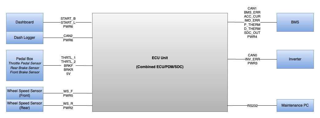
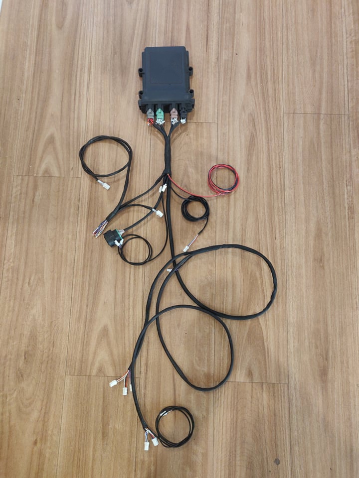
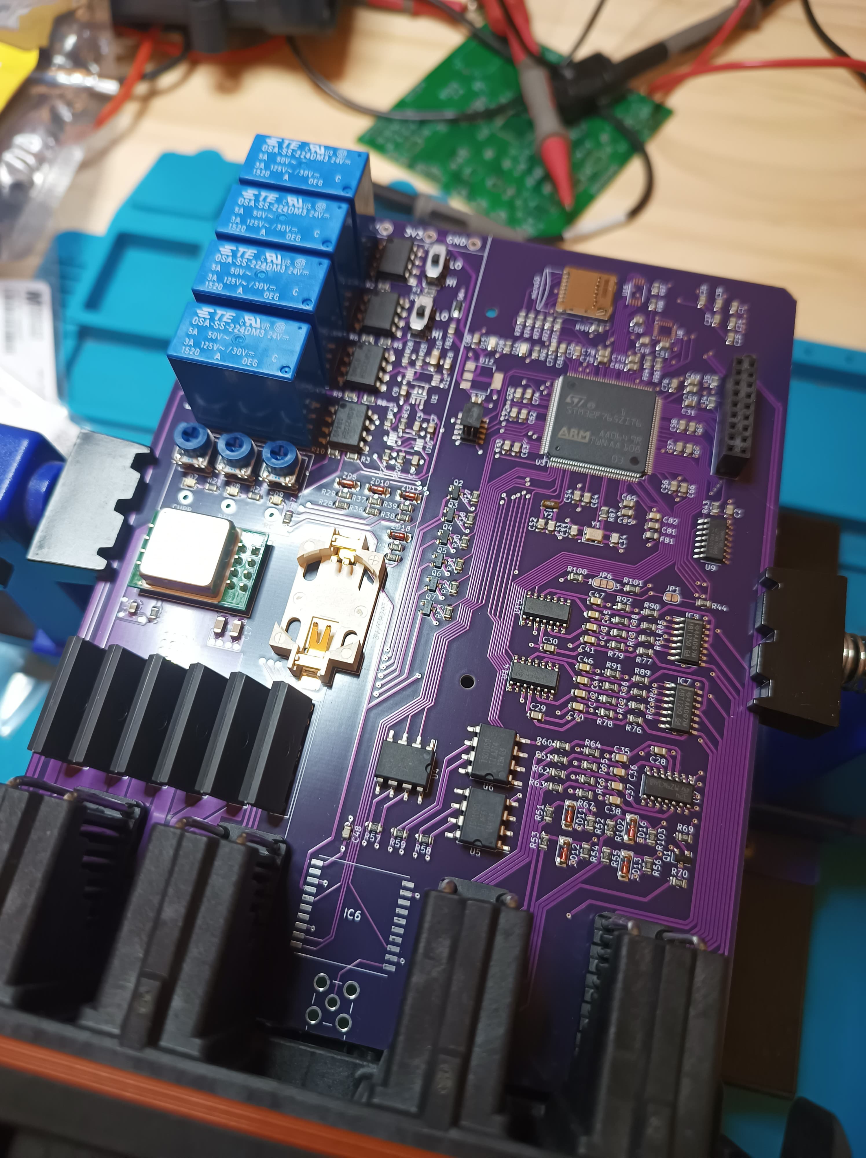
This project uses submodules. Be sure to fetch submodules when cloning and pulling.
git clone <URL> --recurse-submodulesor
git pull --recurse-submodulesfirmware Firmware capable of running on the reference hardware.hardware Reference hardware design.tools Tools used to support operating the ECU.For more information on sub-components, view the README in the appropriate sub-directory.
firmware/src/vcu/vehicleLogic.firmware/src/vcu/device.firmware/src/vcu/vehicleInterface) is designed to allow the drivers to be easily replaced without requiring re-work of the vehicle logic components.firmware/src/vcu/startup/initialize.c dictates what software components are started in run-time.Below are detailed descriptions on the ECU hardware and firmware. They are also avilable as dedicated docs in hardware/README.md and firmware/README.md.
[blocked]hardware/README.md
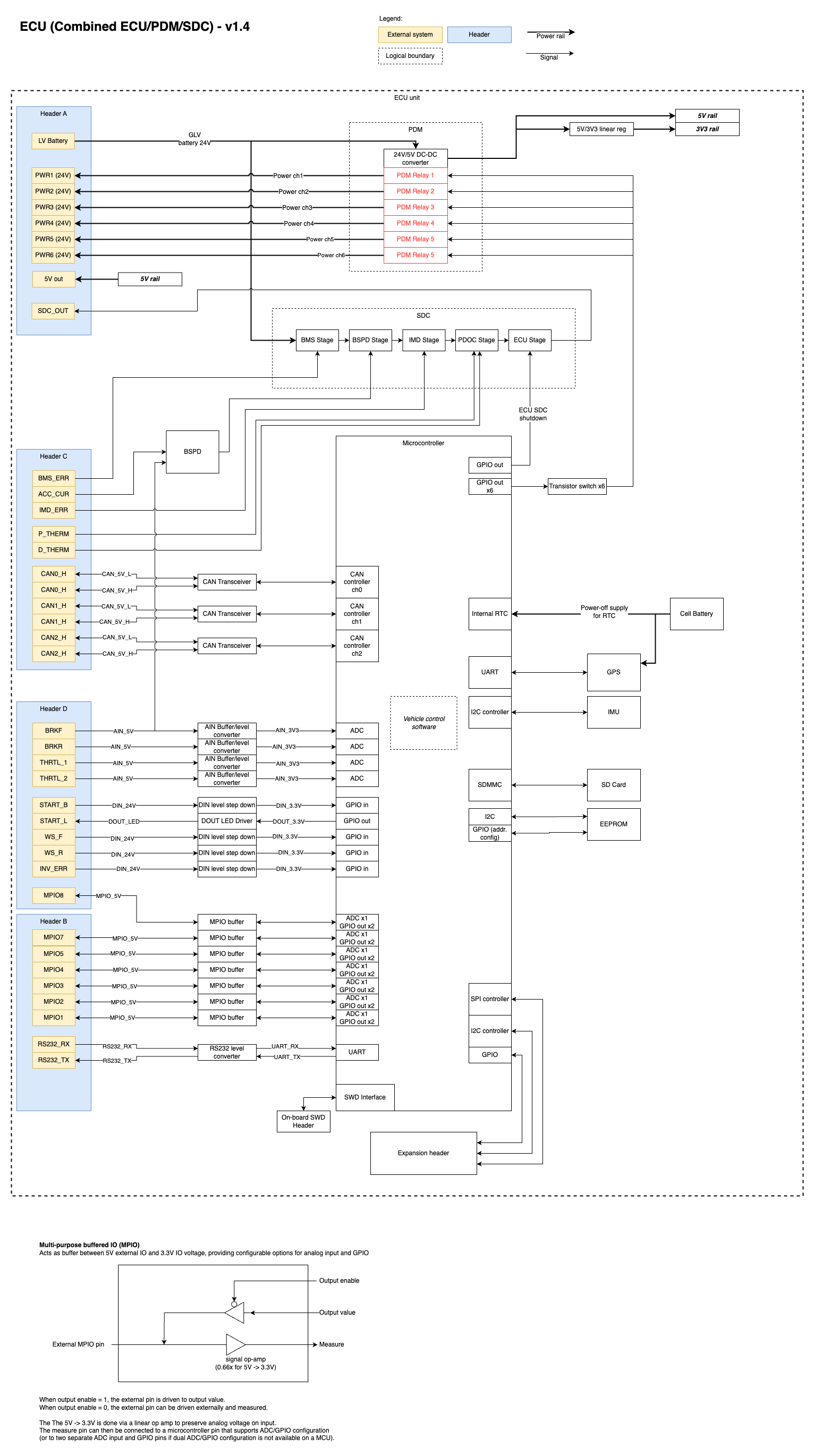
The ECU hardware provides a unified solution for several circuits required for a custom EV build:
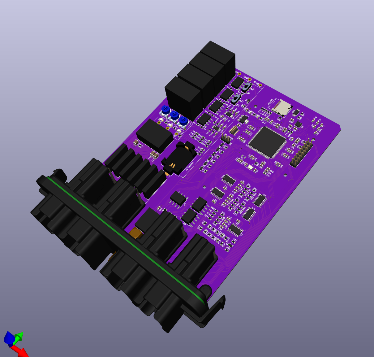
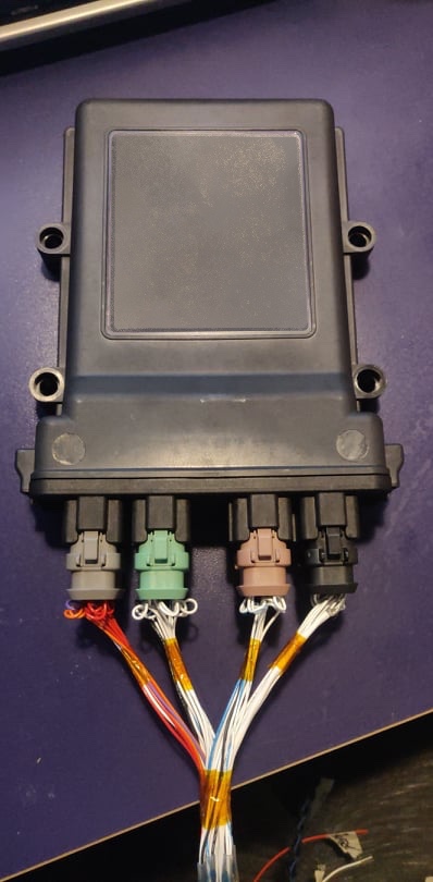
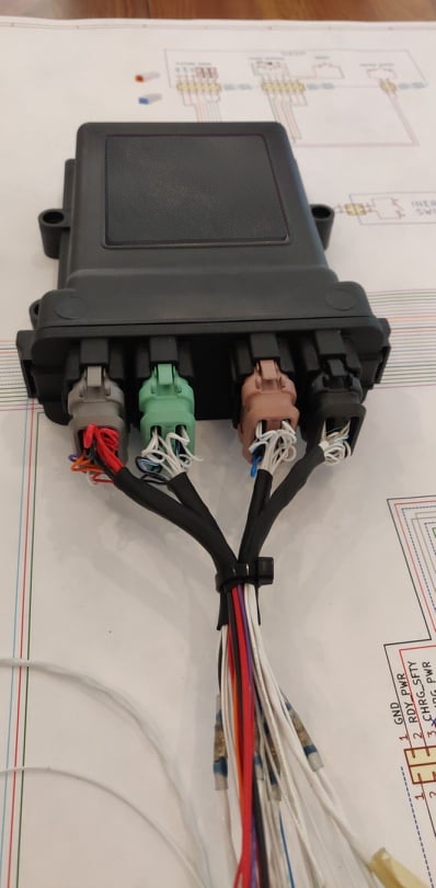
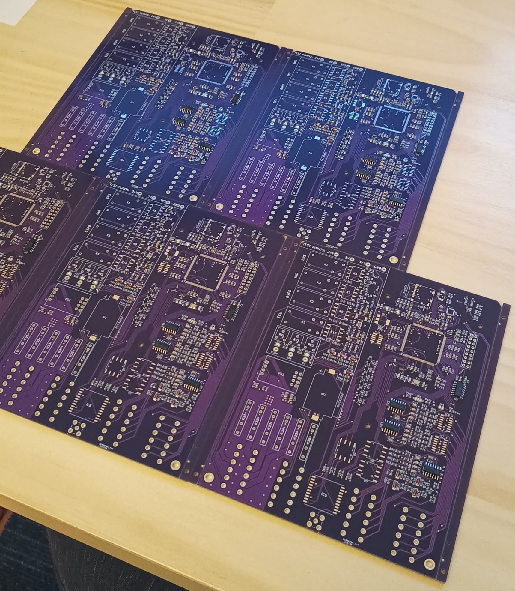
Non-assembled PCBs.
View ECU_Schematic_Print.pdf for the schematic PDF print.
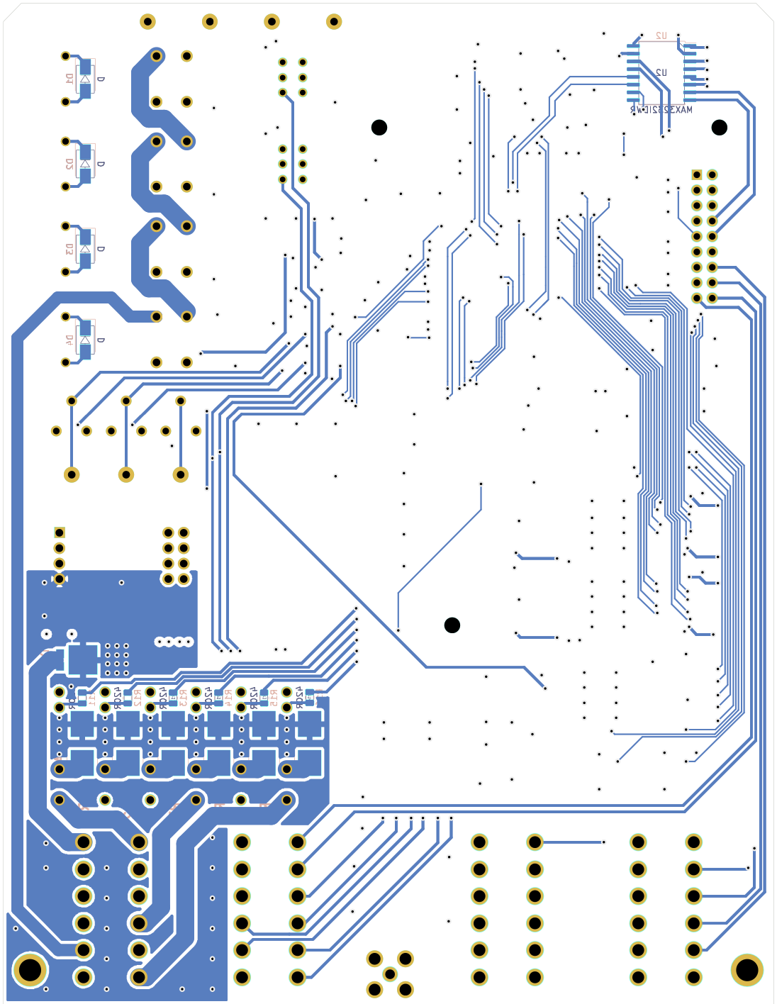
The PCB is laid out in 4 layers:
| Combined | Layer 1 | Layer 2 | Layer 3 | Layer 4 |
|---|---|---|---|---|
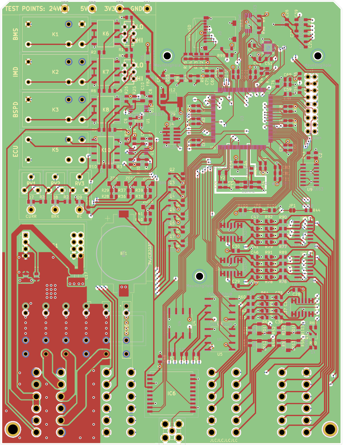 | 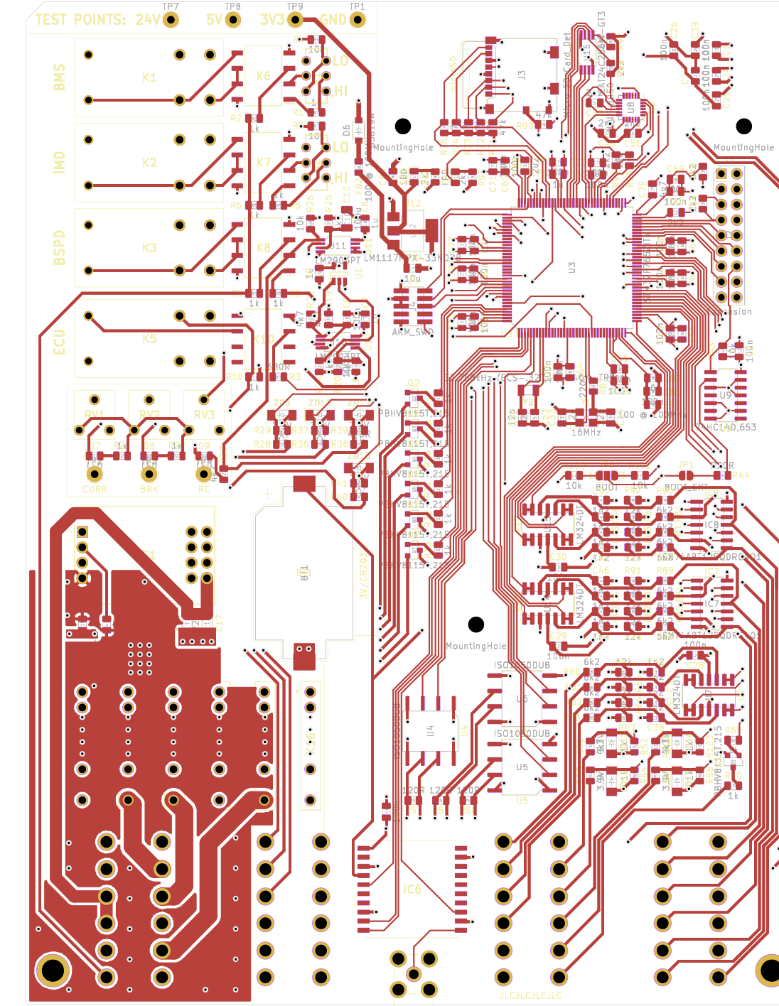 | 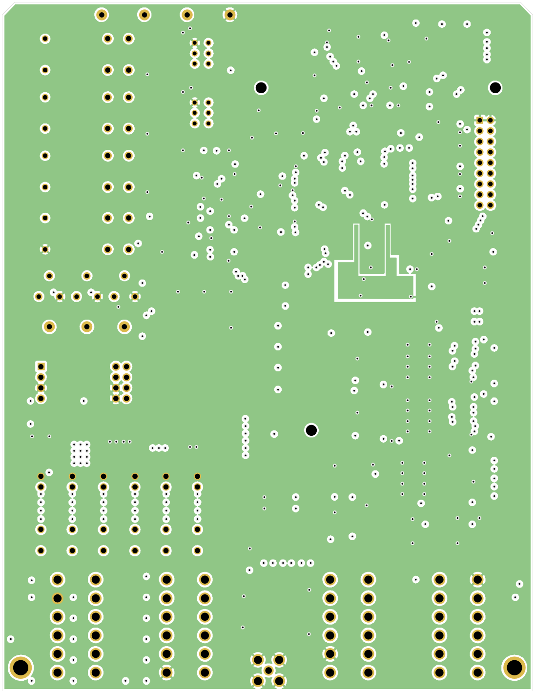 | 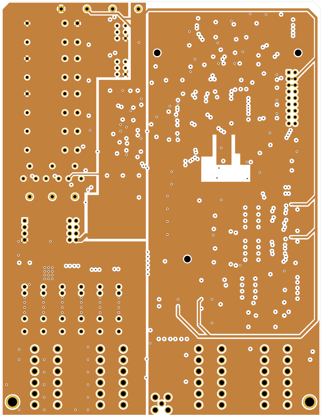 |  |
| External Pin | Description | Signal Type | Firmware Usage |
|---|---|---|---|
| A1 | Power output Ch 1 | Power Out (24V) | Power channel control - Unused, Spare sensor rear |
| A2 | Power output Ch 2 | Power Out (24V) | Power channel control - Wheel speed sensor rear |
| A3 | Power output Ch 3 | Power Out (24V) | Power channel control - Inverter |
| A4 | Power output Ch 4 | Power Out (24V) | Power channel control - BMS |
| A5 | Power output Ch 5 | Power Out (24V) | Power channel control - Spare sensor front, wheel speed sensor front |
| A6 | Power output Ch 6 | Power Out (24V) | Power channel control - Dashboard |
| A7 | Shutdown circuit (SDC) Reset | DIN (5V) | |
| A8 | SDC Out | DOUT (24V) | Vehicle state machine - fault monitoring |
| A9 | Power output (5V) Ch 1 | Power Out (5V) | |
| A10 | Power output (5V) Ch 2 | Power Out (5V) | |
| A11 | Ground | Ground | |
| A12 | LV Battery +24V | Power In (24V) | |
| B1 | Ground | Ground | |
| B2 | RS232 TX | Out (RS232) | PC Interface |
| B3 | RS232 RX | In (RS232) | PC Interface |
| B4 | Internal spare 1 | * | |
| B5 | Programming mode | DIN (5V) | PC Interface (firmware updates) |
| B6 | Configurable IO 5V 1 (MPIO1) | DIO/AIN (5V) | Unused, Spare sensor rear |
| B7 | Configurable IO 5V 2 (MPIO2) | DIO/AIN (5V) | Unused, Spare sensor rear |
| B8 | Configurable IO 5V 3 (MPIO3) | DIO/AIN (5V) | Unused, Spare sensor rear |
| B9 | Configurable IO 5V 4 (MPIO4) | DIO/AIN (5V) | Unused, Spare sensor rear |
| B10 | Configurable IO 5V 5 (MPIO5) | DIO/AIN (5V) | Unused, Spare sensor front |
| B11 | Configurable IO 5V 6 (MPIO6) | DIO/AIN (5V) | Unused, Spare sensor front |
| B12 | Configurable IO 5V 7 (MPIO7) | DIO/AIN (5V) | Unused, Spare sensor front |
| C1 | Internal spare 2 | * | |
| C2 | Internal spare 3 | * | |
| C3 | CAN0 L | CAN L | Inverter CAN bus (Cascadia motion CAN message protocol) |
| C4 | CAN0 H | CAN H | Inverter CAN bus (Cascadia motion CAN message protocol) |
| C5 | CAN1 L | CAN L | BMS (custom Orion BMS CAN configuration) |
| C6 | CAN1 H | CAN H | BMS (custom Orion BMS CAN configuration) |
| C7 | Ground (CAN bus shielding) | Ground | |
| C8 | CAN2 H | CAN H | Unused, provisioned for dashboard |
| C9 | CAN2 L | CAN L | Unused, provisioned for dashboard |
| C10 | Battery current sensor for BSPD | AIN (5V) | |
| C11 | BMS Error | DIN (24V) | Vehicle state machine - fault monitoring |
| C12 | Insulation Monitoring Device (IMD) Error | DIN (24V) | Vehicle state machine - fault monitoring |
| D1 | Configurable IO 5V 8 (MPIO8) | DIO/AIN (5V) | Unused, Spare sensor front |
| D2 | Hall effect sensor | DIN (24V) | Wheel speed (rear) hall effect sensor |
| D3 | Hall effect sensor | DIN (24V) | Wheel speed (front) hall effect sensor |
| D4 | Inverter Error | DIN (24V) | Vehicle state machine - fault monitoring |
| D5 | Start button | DIN (24V) | Vehicle state machine - start button |
| D6 | Output LED | 1kOhm BJT sink for LED | Vehicle state machine - state indicator |
| D7 | Ground | Ground | |
| D8 | Ground | Ground | |
| D9 | Analog sensor | AIN (5V) | Thottle sensor B |
| D10 | Analog sensor | AIN (5V) | Thottle sensor A |
| D11 | Analog sensor | AIN (5V) | Brake pressure (rear) sensor |
| D12 | Analog sensor | AIN (5V) | Brake pressure (front) sensor |
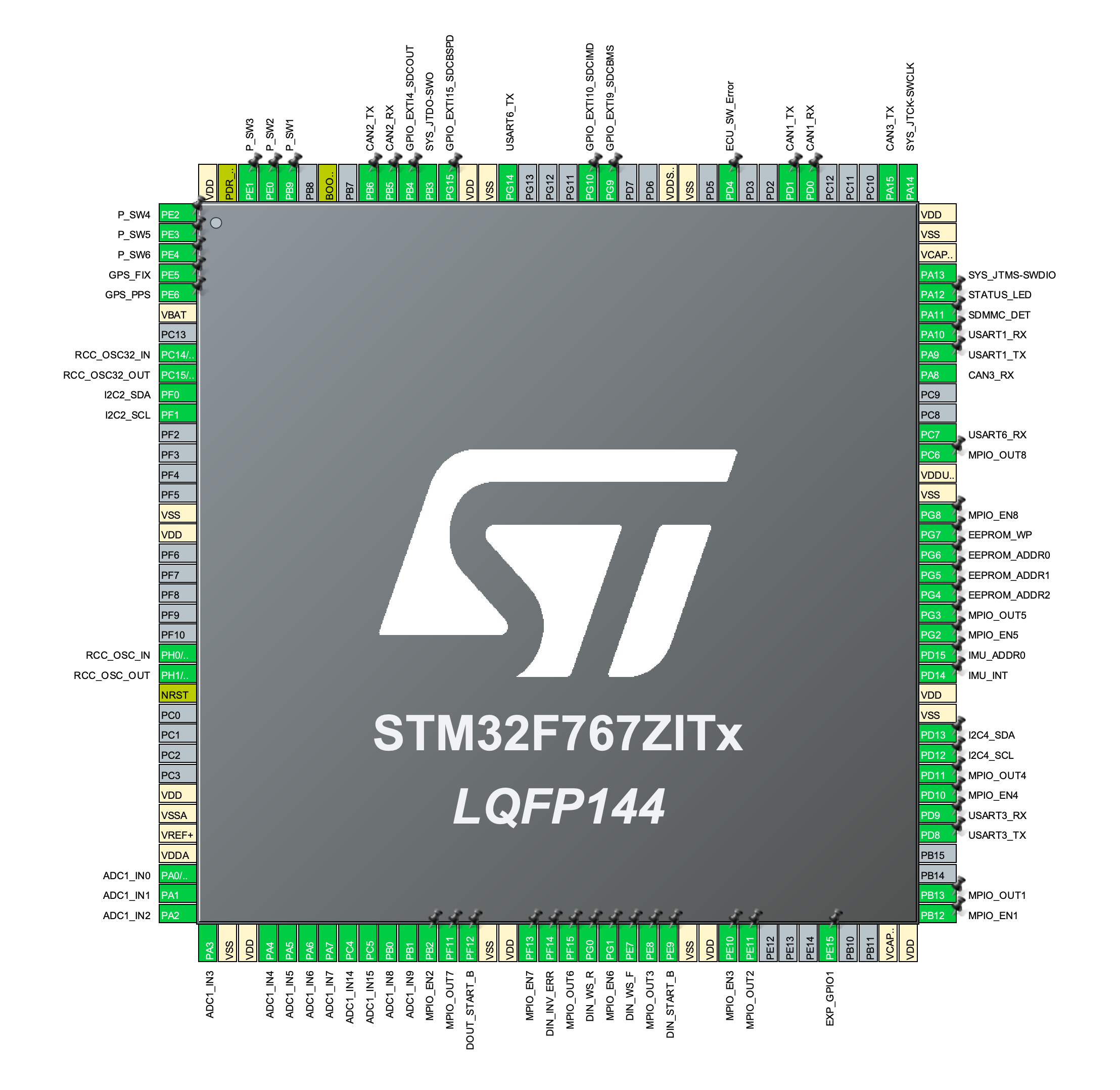
Pin assignments for the internal STM32F7 microcontroller
[blocked]firmware/README.md
The ECU is responsible for overseeing the vehicle state and controlling the vehicle's operation from driver input and operating all devices associated with this process.
The ECU software implements:
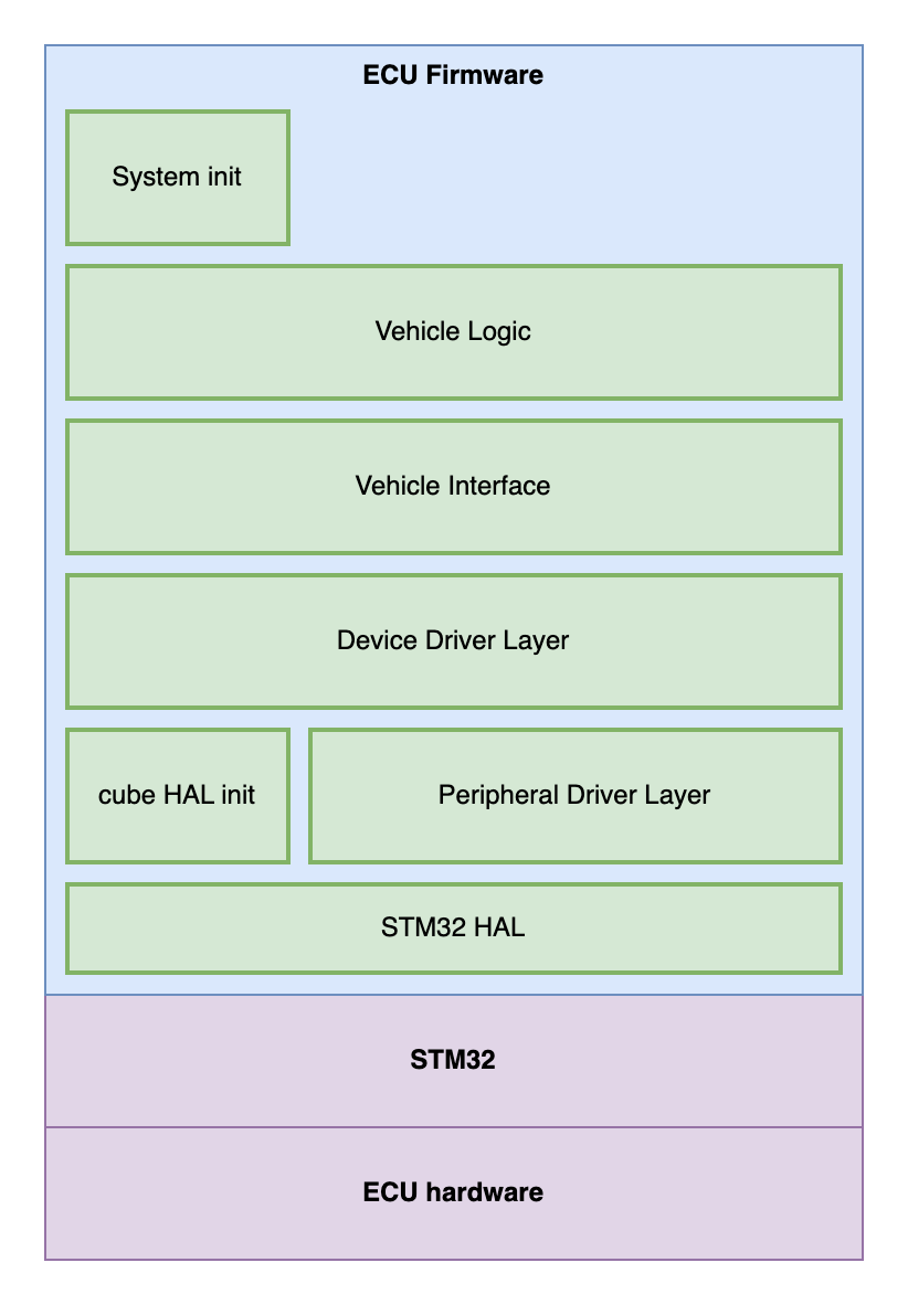
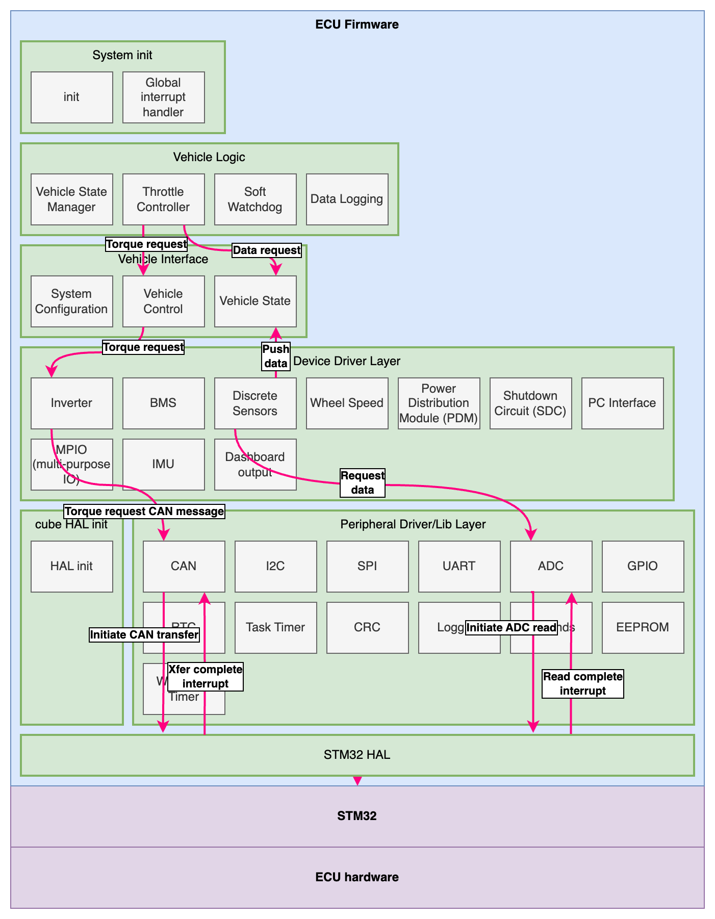
The firmware is comprised of the following layers:
Visualized:
doc Supporting assets for docssrc
vcu Firmware specific to vehicle control unit.system-lib Symlink to common MCU firmware.hal STM32 HAL.test VCU tests (overlayed on top of system-lib tests)The library is tested via a suite of unit tests contained under test. These unit tests leverge the unit testing framework, Unity.
The tests can be executed by invoking run_tests.sh
Executing the tests will generate a code coverage report using lcov.
This will also invoke the unit tests from evfirmware-lib (System/)
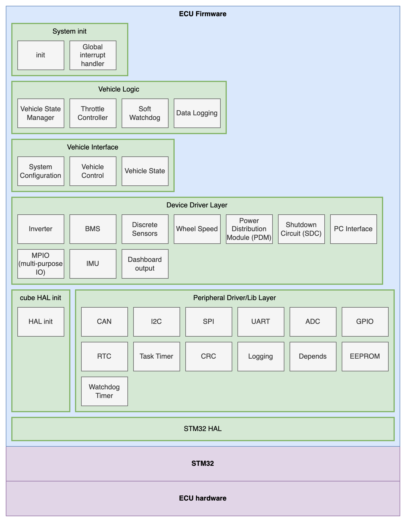
Expanding on the high level firmware stack from above, we can see all the software components:
To visualize the flow of data through this system, we can consider a few examples:
The driver will:
The ECU firmware will, internally:
Once the driver puts the vehicle into it's drive state (as above), then pressing the accelerator should apply power to the wheels.
The process internal to the ECU:
To visualize this flow of data needed by the vehicle control module:
The modules with RTOS tasks are arranged into the following priorities.
The RTOS (FreeRTOS) uses preemption and task priorities, and round robin scheduling for equal priorities. Only modules that have RTOS tasks are shown here. The remaining drivers are invoked within an existing task context.
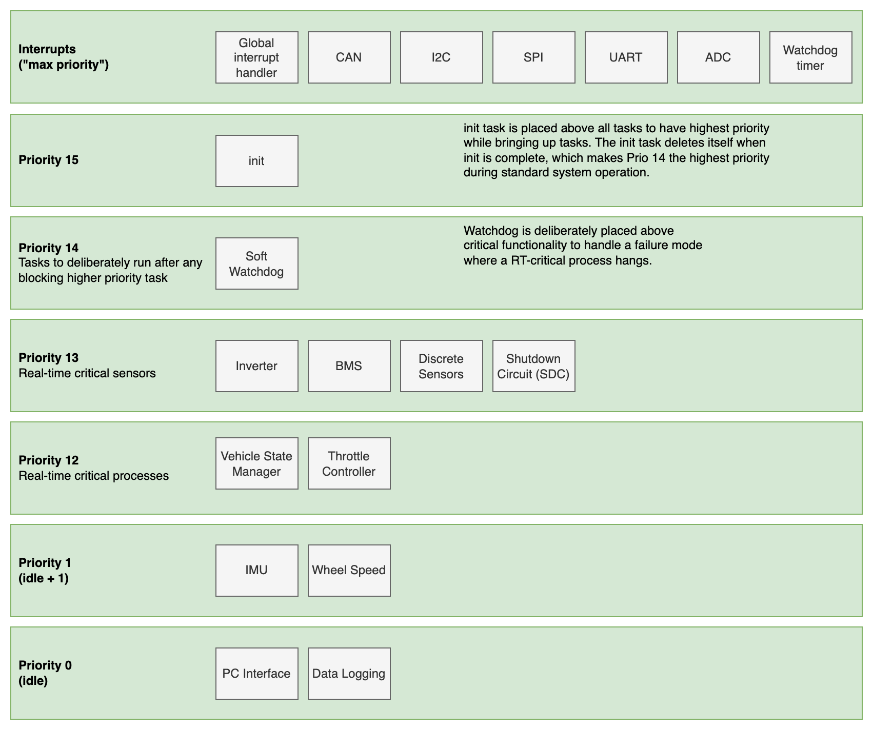
The priorities are selected to achieve:
Prio(RT critical sensors) > Prio(RT critical logic).Prio(soft watchdog) > Prio(all RT critical code) such that:
These priorities, in conjunction with the scheduler, enact the following de facto state machine:
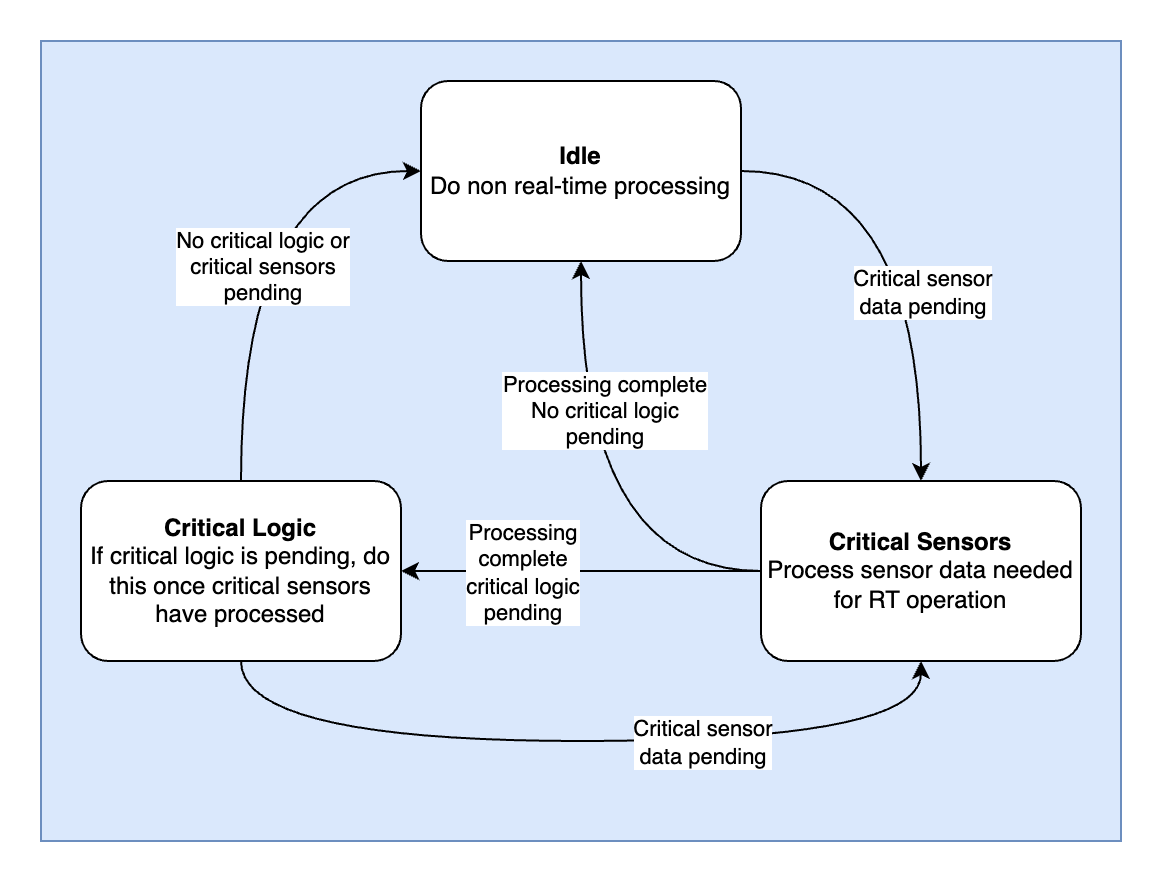
This state machine is not explicitly coded as a state machine in the source, it is deliberate emergent behavior of the scheduler.
All critical logic registers with the watchdog handler. The watchdog handler will trigger a system fault if any critical logic is not handled in a timely manner.
As the name suggests, this module is responsible for calling the init method of all other required modules in the system, and doing so in the correct order.
The init module maintains local ownership of the data structures required for all devices. It does not expose them in the global context.
The init module will create an init task, where all initialization methods are invoked from. Many init methods (for other modules) will create further RTOS tasks. Upon init completion, the init task will be deleted, however the data storage will remain.
This is really a sub-component of the init module, but broken out explicitly for clairty. Certain higher level drivers require some code to run from an interrupt handler. In some instances, the timing and frequency of these events would prohibit this from being done via RTOS task notifications (for example, the wheel speed sensors may run at several kHz, but perform very simple code for each ISR routine). The global interrupt handler simply implements the ISR routine, and calls each module's ISR as needed.
The Vehicle State Manager is responsible for two tasks:
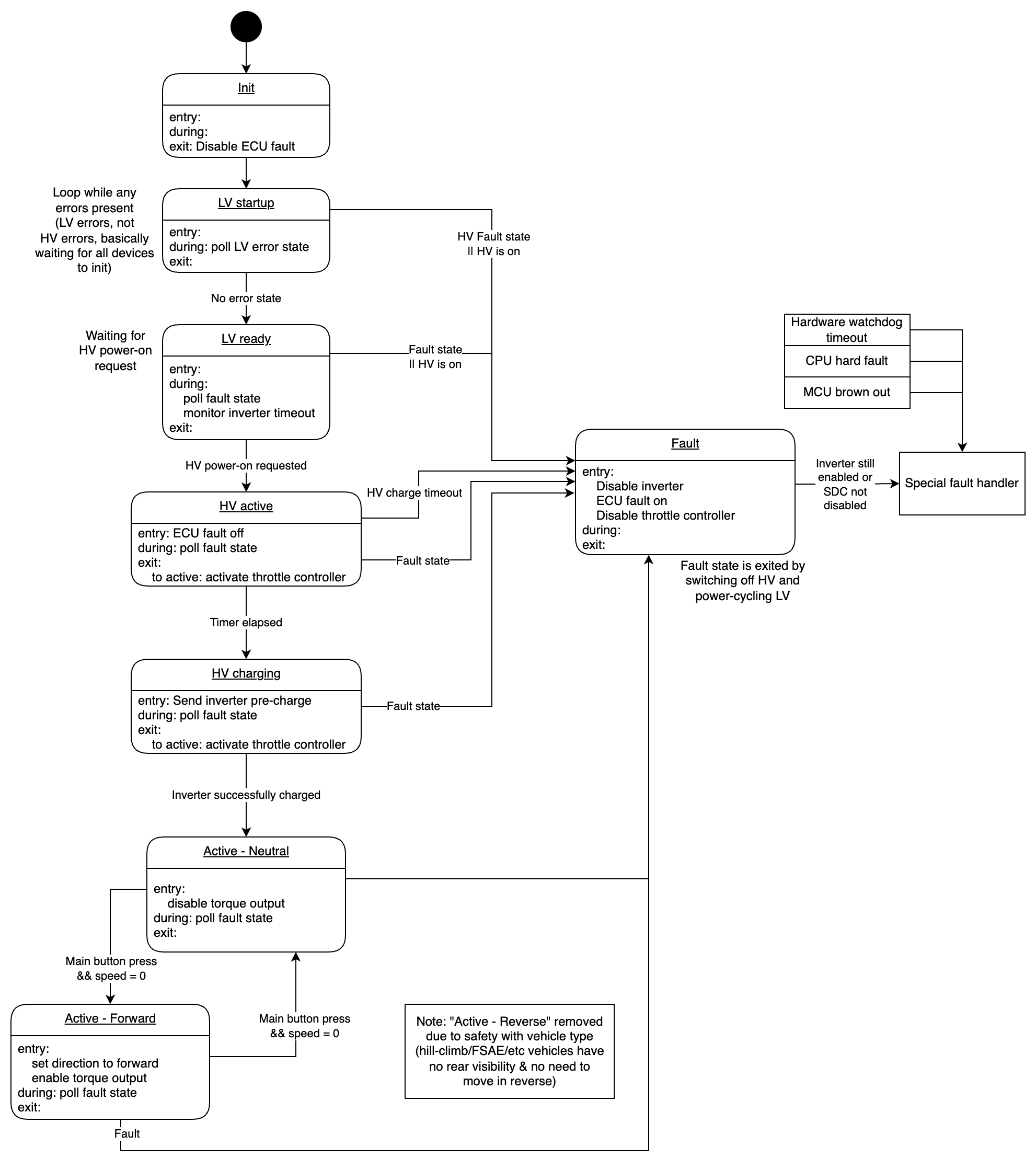
The state diagram essentially follows:
As noted in the diagram, there is no reverse drive state due to hill-climb/FSAE/etc vehicles having no rear visibility & no need to move in reverse.
Faults are split into two categories: Drive Faults and LV System Faults.
LV ready state and onwards. Earlier during init (i.e. LV startup state), it is assumed that the LV systems may be in unsable states as they are initializing. After LV startup, all critical systems must remain in a known good state.All faults are encoded into an error value. They are encoded as a binary one-hot system (i.e. individual faults are all a power of 2) such that multiple errors can be expressed as a logical OR of their individual error codes. Fault codes are encoded as a 32-bit word. LV System Faults occupy the lower 8 bits and Drive Faults oppupy top 24 bits.
| Component | Fault Condition | Configuration | Error Value | Notes |
|---|---|---|---|---|
| Inverter/motor | CAN message timeout | Timeout period configurable | 0x00000001 | |
| BMS | CAN message timeout | Timeout period configurable | 0x00000002 | |
| Inverter | Inverter state is unexpected | 0x00000004 | This code is only generated when the vehicle state is LV Startup. An unexpected inverter state from any other vehicle state would be error 0x01000000. | |
| Soft Watchdog Timeout | The soft watchdog task indicates a critical task is hung (not vehicle state manager) | 0x00000008 | A fault in the vehicle state manager is handled as a special fault (described in Special Faults). |
| Component | Fault Condition | Configuration | Error Value | Notes |
|---|---|---|---|---|
| Accelerator Pedal | Outside of calibrated range | Calibration of pedal can be configured | 0x00000100 | A failure mode of a disconnected sensor would be handled here. |
| Accelerator Pedal | Redundant sensors disagree | Disagreement tolerance can be configured | 0x00000200 | |
| Brake Pedal | Outside of calibrated range | Calibration of pedal can be configured | 0x00000400 | A failure mode of a disconnected sensor would be handled here. |
| Brake Pedal | Redundant sensors disagree | Disagreement tolerance can be configured | 0x00000800 | |
| Brake Pedal | Accel/brake pedal abuse (both pedals simultaneously pressed) | Can be disabled | 0x00001000 | |
| BMS | Any cell above temperature threshold | Limit configurable | 0x00002000 | |
| BMS | Current draw too high | Limit configurable | 0x00004000 | |
| BMS | Any cell above threshold voltage | Limit configurable | 0x00008000 | |
| BMS | State of charge too low | Limit configurable | 0x00010000 | |
| BMS | BMS fault indicator | 0x00020000 | ||
| Inverter/motor | Inverter internal temperature too high | Limit configurable | 0x00040000 | |
| Inverter/motor | IGBTs above allowable temp | Limit configurable | 0x00080000 | Thermal throttling could be considered before this occurs (not currently implemented) |
| Inverter/motor | Motor above allowable temp | Limit configurable | 0x00100000 | Thermal throttling could be considered before this occurs (not currently implemented) |
| Inverter/motor | Current draw too high | Limit configurable | 0x00200000 | |
| Inverter/motor | Inverter fault indicator | 0x00400000 | ||
| Inverter/motor | Inverter fault message | 0x00800000 | ||
| Inverter/motor | Inverter state is unexpected | 0x01000000 | This would result in a 0x00000004 if it occurs during the LV Startup vehicle state. |
A number of scenarios require more extreme management of a fault:
If these occur, the firmware will immeidately run a special fault handler where it moves the vehicle into a safe state by:
These operations are done with as little firmware layers as possible - they will write directly to hardware (i.e. they bypass the Vehicle Control component, and the drivers below this, as it is likely unclear what has caused this fault).
The soft watchdog is an indepent RTOS task where, during init, other critical tasks will register to the soft watchdog. During runtime, these critical tasks must "feed" the watchdog (just call a notification task to reset their respective counters). The watchdog will count how long it has been since a feed from each critical task. If the count exceeds a timeout, it will update a flag in the vehicle state, where the state machine manager component will read this and act accordingly.
The soft watchdog will monitor the vehicle state. If a fault state is not entered within a small amount of time, the special fault handler will be invoked.
The soft watchdog task is also responsible for feeding the hardware watchdog. The soft watchdog should be able to account for all faults that don't prevent the task from running, which is where the hardware watchdog will take over (and run the special fault handler).
This module will read the throttle pedal sensor value, translate this via a torque map to a request of Nm, and requests this from the inverter. This operation (or whether the module sits idle) is controlled via the API, and is called by the vehicle state manager.
The module contains a torque map. The exact torque value is found by linearly interpolating between entries of the torque map.
The torque map implemented is:
| Accelerator pedal % | Torque (Nm) |
|---|---|
| 0% | 0 Nm |
| 10% | 0 Nm |
| 50% | 100 Nm |
| 70% | 200 Nm |
| 100% | 500 Nm |
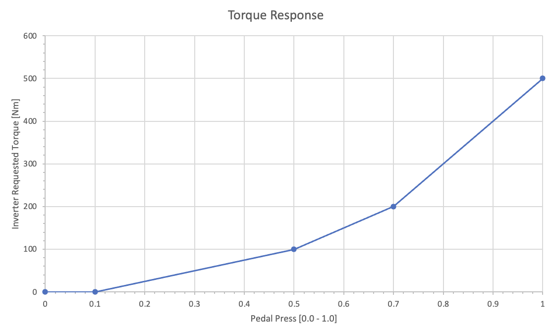
Single pedal driving and regenerative braking are currently not supported. Only mechanical braking is supported.
Any regenerative braking would be added to this module, however.
The data logging module simply makes a copy of system state and logs it to a file on the SDMMC at on a regular periodic interval.
Note: The system configuration as described here is is not currently implemented. The code currently implements a default config data structure.
The system configuration is a table of values used by the rest of the system during init. The table is populated by fields stored on the extermal EEPROM.
Configuration options include the pedal calibration, or fault timeout periods. The full list of configurations are available in firmware/src/vcu/vehicleInterface/config/configData.h.
Configuration values are stored on the 256Kbit (32KiB) EEPROM. To simplify development and modification, the external EEPROM is loaded with an instance of littlefs. The configuration items are stored as files under /config/. Their paths represent the field values and the file contents are the configuration value. Each file has a corresponding *.crc32 checksum file.
E.g. for the calibration of accelerator pedal sensor A, the files are:
/config/inputs/accelPedal/calibrationA/rawLower Raw ADC value corresponding to the pedal being 0% pressed./config/inputs/accelPedal/calibrationA/rawLower.crc32 32-bit CRC of rawLower/config/inputs/accelPedal/calibrationA/rawUpper Raw ADC value corresponding to the pedal being fully pressed./config/inputs/accelPedal/calibrationA/rawUpper.crc32 32-bit CRC of rawUpperThe PC interface can also query and update the values on the EEPROM, but they are only loaded into the system configuration module at startup.
The Vehicle Control module is really just a shim. It contains APIs that allow control over any aspect of the car. Internally, it will just invoke one of the device drivers to achieve the requested funtionality.
Current operations supported:
The vehicle state module holds the current physical state of the car and owns the sychronization primitives controlling thread-safe access to these variables.
You can safely copy the state by invoking VehicleState_CopyState. Alternatively, individual elements can be accessed by using VehicleState_AccessAcquire and then reading or writing values. VehicleState_AccessRelease must always be used after a successful acquire.
The vehicle state is conceuptialized as a tree, and currently contains:
This module will handle CAN bus messages from the inverter, updating the state machine, and will construct CAN bus messages to send to the inverter based on the driver API.
The inverter driver is based a Cascadia Motion Sytems CM200 inverter.
This module will handle CAN bus messages from the inverter, updating the state machine.
The BMS driver is based on an OrionBMS 2 with the following CAN message configuration:
| CAN ID | Message Name | Frequency | Data[0] | Data[1] | Data[2] | Data[3] | Data[4] | Data[5] | Data[6] | Data[7] |
|---|---|---|---|---|---|---|---|---|---|---|
| 0x301 | Max cell state | 100 Hz | Max cell temperature LSB | Max cell temperature MSB | Max temperature cell ID | Max cell voltage LSB | Max cell voltage MSB | Max voltage cell ID | 0 | 0 |
| 0x302 | Min cell state | 100 Hz | Min cell temperature LSB | Min cell temperature MSB | Min temperature cell ID | Min cell voltage LSB | Min cell voltage MSB | Min voltage cell ID | 0 | 0 |
| 0x303 | Pack state | 100 Hz | DC current LSB | DC current MSB | Bus voltage LSB | Bus voltage MSB | State of charge LSB | State of charge MSB | 0 | 0 |
| 0x304 | Status | 100 Hz | Counter | Populated Cells | Failsafe status LSB | Failsafe status MSB | 0 | 0 | 0 | 0 |
All fields size >1 byte are sent LSB first.
Data Formats:
| Field | Data Type | Encoding | Range | Notes |
|---|---|---|---|---|
| Temperature | int16 | Temperature in degrees C x10 | -3276.8 °C to +3276.7 °C | |
| Cell Voltage | int16 | Voltage in Volts x100 | -327.68 V to +327.67 V | |
| Cell ID | uint8 | Raw cell number | 0 to 255 | |
| Pack Current | int16 | Current in Amps x10 | -3276.8 A to +3276.7 A | |
| Pack Voltage | int16 | Current in Volts x10 | -3276.8 V to +3276.7 V | |
| State of charge | uint16 | Percentage x100 | 0% to 655.35% | |
| Counter | uint8 | Raw value | 0 to 255 | Increments for every message |
This module perodically reads discrete sensors (GPIO inputs and ADC inputs) and pushes the results to the vehicle state.
This module currently handles:
The module updates these values on a regular 100Hz update tick.
The wheel speed sensor measures the speed of a hall effect wheel speed sensor. The sensor driver assumes that the spacing of the teeth is uniform, and that the high/low size of the sensor teeth are equal. The number of teeth is configurable at init. The sensor will produce a new reading every 1 second.
The voltage input appears as a PWM signal. The frequency of the PWM signal encodes the wheel speed.
The module implements an ISR (that is invoked by the Global Interrupt Handler). This does a GPIO read on the wheel speed sensor hall effect inputs, and then pushes these values to an RTOS queue. In the main task, the driver pulls these readings off, and calculates the number of 0V -> 24V transitions over the 1s period, informing a simple conversion to RPM.
This module is simply an abstraction to access the correct GPIO pins to control the 24V power output channels. When updating a power channel, the module will also reflect the change in the Vehicle State module.
The module serves two purposes:
The Global Interrupt Handler invokes the SDC ISR method when the GPIO interrupt is triggered. The SDC ISR method will read the state of all the SDC inputs via a simple GPIO read. If any errors are asserted, a FreeRTOS task notification is used to awake the SDC task, finally updating the field in the Vehicle State.
The PC interface implements the serial (RS232) interface to a debug/control computer.
The following functions can currently be performed over the interface:
The serial interface communication is performed via a Modbus protocol. This allows the debug PC to multiplex the different types of data and handle independent operations. It also allows easier expansion of the PC interface.
Words are transmitted MSB first.
The console is configured to 115200 bps.
| Byte | Content |
|---|---|
| 0 | Start |
| 1 | Address[1] |
| 2 | Address[0] |
| 3 | Function[1] |
| 4 | Function[0] |
| 5 .. 5+(n-1) | Data[n..0] |
| 6+(n-1) | CRC[3] |
| 7+(n-1) | CRC[2] |
| 8+(n-1) | CRC[1] |
| 9+(n-1) | CRC[0] |
| 10+(n-1) | End[1] |
| 11+(n-1) | End[0] |
| Section | Length (Bytes) | Description |
|---|---|---|
| Start | 1 | Payload begin. Equal to 0x80 |
| Address | 2 | Address of receiver |
| Function | 2 | Message type |
| Data | n | Message data |
| CRC | 4 | 32-bit cyclic redundancy check |
| End | 2 | Frame end. Equal to |
| Address | Target |
|---|---|
| 0x01 | ECU |
| 0x02 | Debug PC |
| Message Name | State Broadbast |
| Function | 0x01 |
| Transmit Rate | 1Hz per data field |
| Send Address | 0x01 |
| Target Address | 0x02 |
| Data Length | 7 |
| Message Length | 18 |
| Description | Transmit live vehicle data from the Vehicle Interface layer. |
| Data[0] | Data[1] | Data[2] | Data[3] | Data[4] | Data[5] | Data[6] |
|---|---|---|---|---|---|---|
| FieldID[1] | FieldID[0] | FieldSize | Data[3] | Data[2] | Data[1] | Data[0] |
FieldID ID of field. IDs are located at firmware/src/vcu/device/pcinterface/fieldId.h.FieldSize size of Data (bytes).Data[3..0] latest contents of field.| Message Name | Log Message |
| Function | 0x02 |
| Transmit Rate | Variable (upon ECU log event) |
| Send Address | 0x01 |
| Target Address | 0x02 |
| Data Length | 32 |
| Message Length | 43 |
| Description | Continuously dumps print/log messages. Transmits up to 32 bytes at once - no more to avoid data corruption. Unused bytes are left as zeros and are ignored. Note that this message could be read with an incorect CRC when displaying output as it just contains ASCII text. |
| Data[0..31] |
|---|
| LogChar[0..31] |
LogChar ASCII byte| Message Name | Debug Message (ECU -> PC) |
| Function | 0x09 |
| Transmit Rate | Variable (upon response generated) |
| Send Address | 0x02 |
| Target Address | 0x01 |
| Data Length | 8 |
| Message Length | 17 |
| Description | Transmits a text command to the ECU. For help with the debug terminal, issue the command help. View more details at firmware/src/vcu/device/pcinterface/debugtermcommands.c. |
| Data[0..7] |
|---|
| CmdStr[0..7] |
CmdStr String to append to the internal command buffer.This message ID is currently TBD. The current implementation prints log messages when handling debug console requests.
Implements a simple wrapper around the multi-purpose IO components on the ECU board. Allows an ADC read operation, or simple GPIO read/write.
The module will set the output mode pin. As with the ADC/GPIO drivers, the STM32-specific pin configuration is done seperately.
The board contains a MPU-6050 IMU. The IMU interfaces over the I2C bus.
The data from the IMU (accelerometer and gyroscope) would be pushed into the vehicle state.
This data is currently not used for any vehicle control and exists for offboard analysis.
This module is currently unimplemented.
The current dashboard consists of a single LED output and button input. The dashboard output controls a single GPIO pin.
The CAN bus module provides a thread safe wrapper around the CAN bus hardware on the STM32. The CAN interface is accessed via the STM32 HAL internally.
FreeRTOS queues and semaphores are used to gate access to the peripheral, with access to three in parallel possible. The internal queues allow any FreeRTOS thread/task to enqueue a CAN tx message by making CAN_SendMessage thread safe. The module does this by using CAN_SendMessage to place pending messages on a queue and automatically sending queued messages when Tx complete interrupts trigger.
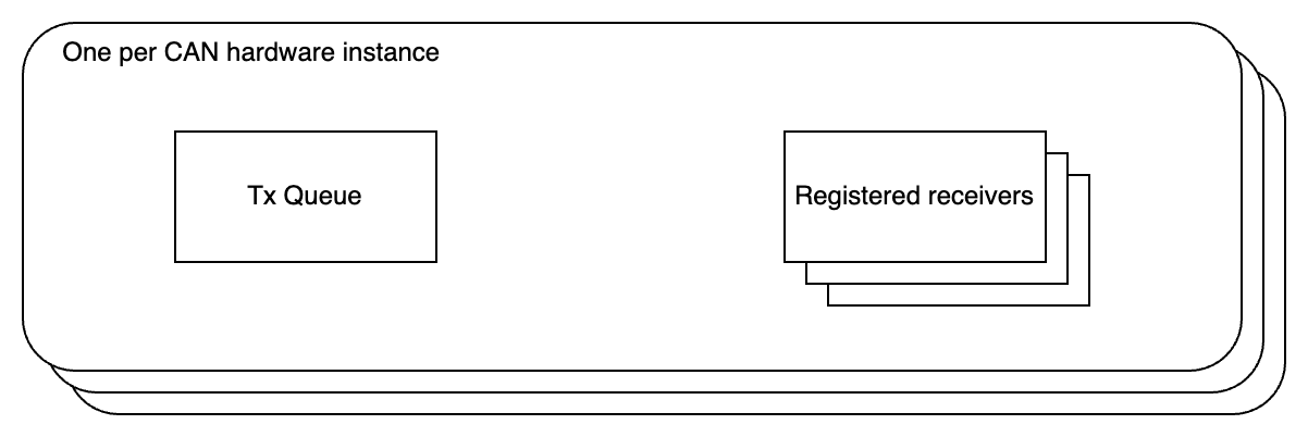
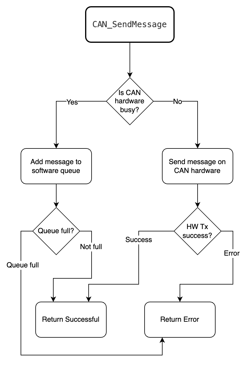
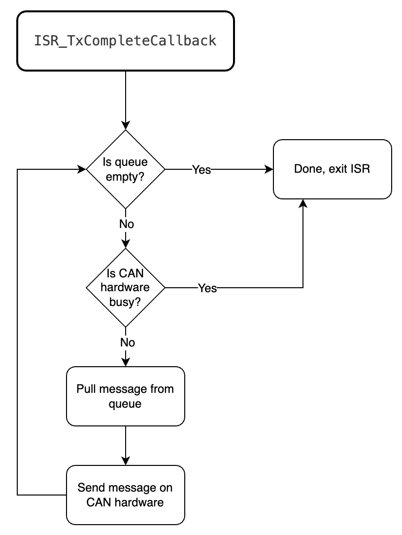
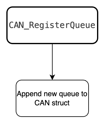
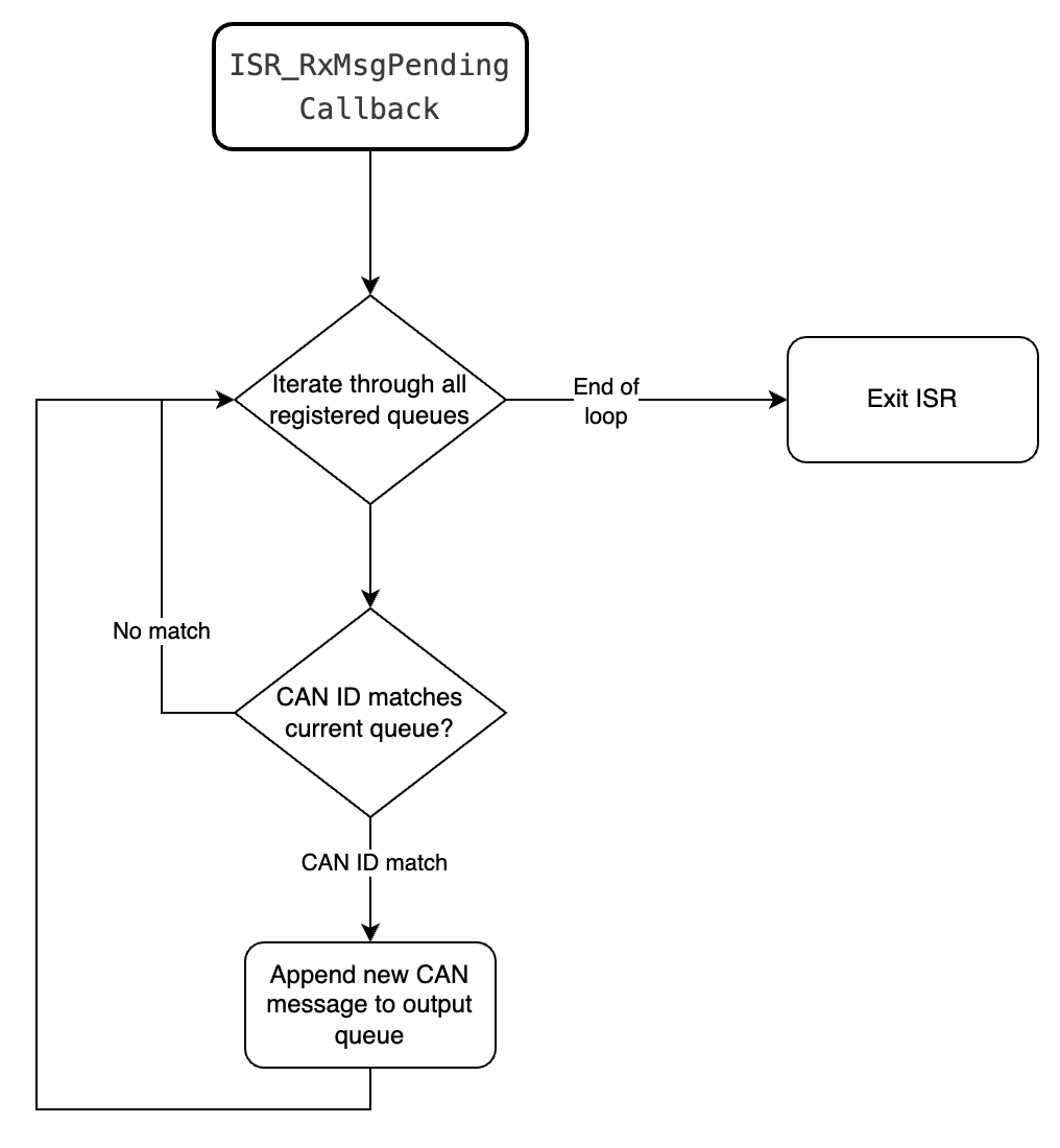
This module also implements the CAN rx ISRs. Other code modules can register to "listen" for CAN messages. The other code modules register a queue where their CAN messages can be placed and a FreeRTOS notification structure to notify. When the rx ISR is triggered, the CAN message is read, the appropriate target queues are found via the registered CAN IDs, the message is copied to the appropriate queues, and the appropriate task notifications are made.
The I2C driver provides a thread safe wrapper of the STM32 HAL DMA I2C interface. The driver will wait for the hardware to become free (up to a timeout).
One difference to the CAN bus driver is that it works synchronously with Read and Write operations, and does not allow for registering for responses (the I2C comms are completed inline).
The SPI driver works similarly to the I2C driver in that it provides a thread safe wrapper around the SPI peripherals. However, a simple SPI transfer (and a blocking transfer) are provided.
The blocking transfer uses the STM32 HAL blocking API and will busy loop while waiting for the transfer to complete.
The non blocking transfer uses DMA to perform the transfer and immediately returns when the transfer has begun.
The UART driver works almost entirely the same as the CAN driver:
UART_SendMessage will either send the message directly to the UART hardware, or place it in a software queue if the hardware is already performing a transfer.The STM32 hardware allows the U(S)ART to be managed via DMA, so this driver utilizes the DMA controller to run the UART interfaces.
The ADC driver configures the ADC peripherals to read via DMA and provide a thread safe interface (a simple ADC_Get once the device is running).
A helper function to apply linear scaling is also provided.
This module of code simply adds an abstraction layer above the STM32 HAL GPIO code to improve code portability. This layer is intended to fully cover the peripheral capabilities, so a simple GPIO wrapper is needed.
Similarly to the GPIO, this module wraps around the STM32 HAL RTC driver.
The task timer module implements the timer ISR and sends FreeRTOS task notifications. Tasks can notify for period notifications (e.g. tasks that run at 100Hz) that allow them to run exactly at a specific frequency.
The depdendent tasks can pend on a notification until the task timer notifies them that they can run. This allows 100Hz tasks to run exactly at 10ms intervals without delay (regardless of run-time jitter).
The hardware is configured with an external crystal, making the timing highly accurate. The timer has been tested to maintain timing accuracy up to 20kHz.
When timing is above 1kHz, FreeRTOS scheduling must be recalculated. This currently isn't in place as the ECU only requires 100Hz.
This module is a simple wrapper around the STM32 CRC calculation hardware.
The logging module's use is to provide the Log_Print method which replaces printf.
The logging module will opertionally output the log data to two sources:
Log_SetSerialStream to consume the log data, and will subsequently encode the logs onto a special serial structure for a connected PC on the UART interface.Each module can use the REGISTER* macros to get a module ID which can be depended on by other module. Modules' init methods can invoke a DEPEND_ON or DEPEND_ON_STATIC method to ensure that other code that a particular module depends on has actually been initialized.
The STM32 HAL is simply the ST Micro provided HAL for the STM32 F7 microcontroller.
| Qty | Value | Footprint | References |
|---|---|---|---|
| 36 | 100n | Capacitor_SMD:C_0805_2012Metric | C1, C2, C5, C24, C25, C26, C27, C28, C29, C30, C39, C48, C54, C55, C56, C57 +20 |
| 25 | 1k | Resistor_SMD:R_0805_2012Metric | R1, R2, R10, R17, R18, R21, R22, R29, R30, R31, R32, R33, R37, R39, R41, R103 +9 |
| 13 | 4k7 | Resistor_SMD:R_0805_2012Metric | R19, R20, R23, R24, R25, R27, R28, R36, R40, R51, R53, R55, R102 |
| 12 | 12k | Resistor_SMD:R_0805_2012Metric | R64, R65, R66, R67, R78, R79, R82, R83, R86, R88, R91, R92 |
| 12 | 1n2 | Capacitor_SMD:C_0805_2012Metric | C35, C36, C37, C38, C40, C41, C42, C43, C44, C45, C46, C47 |
| 12 | 6k2 | Resistor_SMD:R_0805_2012Metric | R60, R61, R62, R63, R76, R77, R80, R81, R84, R85, R89, R90 |
| 8 | 2k2 | Resistor_SMD:R_0805_2012Metric | R34, R35, R93, R94, R95, R96, R97, R98 |
| 8 | 3.3V | Diode_SMD:D_MiniMELF | ZD5, ZD10, ZD11, ZD12, ZD13, ZD16, ZD17, ZD18 |
| 7 | PBHV8115T,215 | Package_TO_SOT_SMD:SOT-23 | Q1, Q2, Q3, Q4, Q5, Q6, Q7 |
| 6 | 0154010.DRL | SamacSys_Parts:0154010DRL | F1, F2, F3, F5, F6, F7 |
| 6 | 10k | Resistor_SMD:R_0805_2012Metric | R4, R7, R26, R43, R100, R101 |
| 6 | 420R | Resistor_SMD:R_0805_2012Metric | R11, R12, R13, R14, R15, R16 |
| 6 | 47k | Resistor_SMD:R_0805_2012Metric | R71, R72, R73, R74, R75, R99 |
| 6 | CPC1706Y | SamacSys_Parts:CPC1706Y | K11, K12, K13, K14, K15, K16 |
| 5 | 1u | Capacitor_SMD:C_0805_2012Metric | C7, C8, C9, C74, C75 |
| 5 | LED | LED_SMD:LED_0805_2012Metric | D7, D8, D9, D14, D15 |
| 4 | 12p | Capacitor_SMD:C_0805_2012Metric | C33, C34, C52, C53 |
| 4 | 5-1419124-7 | SamacSys_Parts:514191247 | K1, K2, K3, K5 |
| 4 | AQW212EHA | SamacSys_Parts:SOP254P962X275-8N | K6, K7, K8, K10 |
| 4 | D | Diode_SMD:D_SMA | D1, D2, D3, D4 |
| 3 | 10K | SamacSys_Parts:3306F1103 | RV1, RV2, RV3 |
| 3 | 120R | Resistor_SMD:R_0805_2012Metric | R57, R58, R59 |
| 3 | 2n2 | Capacitor_SMD:C_0805_2012Metric | C49, C50, C51 |
| 3 | ISO1050DUB | Package_SO:SOP-8_6.62x9.15mm_P2.54mm | U4, U5, U6 |
| 3 | LM324DT | Package_SO:SOIC-14_3.9x8.7mm_P1.27mm | U7, U14, U15 |
| 3 | MountingHole | MountingHole:MountingHole_2.5mm | H1, H2, H3 |
| 2 | 100 @ 100MHz | Inductor_SMD:L_0805_2012Metric | FB1, FB2 |
| 2 | 10u | Capacitor_SMD:C_0805_2012Metric | C79, C80 |
| 2 | 220R | Resistor_SMD:R_0805_2012Metric | R44, R87 |
| 2 | 22u | Capacitor_SMD:C_1206_3216Metric | C17, C18 |
| 2 | 2u2 | Capacitor_SMD:C_0805_2012Metric | C31, C32 |
| 2 | JS202011CQN | SamacSys_Parts:JS202011CQN | S1, S2 |
| 2 | LM2903PT | Package_SO:TSSOP-8_4.4x3mm_P0.65mm | U10, U11 |
| 2 | SN74ABT125QDRG4Q1 | Package_SO:SOIC-14_3.9x8.7mm_P1.27mm | IC7, IC8 |
| 1 | 100k | Resistor_SMD:R_0805_2012Metric | R42 |
| 1 | 100u | Capacitor_SMD:C_1206_3216Metric | C10 |
| 1 | 10n | Capacitor_SMD:C_0805_2012Metric | C82 |
| 1 | 10u/35V | Capacitor_SMD:C_0805_2012Metric | C16 |
| 1 | 16MHz | Crystal:Crystal_SMD_3225-4Pin_3.2x2.5mm | Y1 |
| 1 | 24V | TestPoint:TestPoint_THTPad_D2.5mm_Drill1.2mm | TP7 |
| 1 | 32.768kHz (ECS-.327-9-34QN-TR) | Crystal:Crystal_SMD_3215-2Pin_3.2x1.5mm | Y2 |
| 1 | 3V/CR2032 | Battery:BatteryHolder_Keystone_1060_1x2032 | BT1 |
| 1 | 3V3 | TestPoint:TestPoint_THTPad_D2.5mm_Drill1.2mm | TP9 |
| 1 | 470R | Resistor_SMD:R_0805_2012Metric | R38 |
| 1 | 4u7 | Capacitor_SMD:C_0805_2012Metric | C76 |
| 1 | 5V | TestPoint:TestPoint_THTPad_D2.5mm_Drill1.2mm | TP8 |
| 1 | 619540-1 | SamacSys_Parts:6195401 | J5 |
| 1 | 680R | Resistor_SMD:R_0805_2012Metric | R3 |
| 1 | 74HC14D,653 | Package_SO:SOIC-14_3.9x8.7mm_P1.27mm | U9 |
| 1 | 790 | SamacSys_Parts:790 | IC6 |
| 1 | ARM_SWD | Connector_PinHeader_1.27mm:PinHeader_2x05_P1.27mm_Vertical_SMD | J4 |
| 1 | B5819W | Diode_SMD:D_SOD-123 | D6 |
| 1 | BOOT | Jumper:SolderJumper-3_P1.3mm_Open_RoundedPad1.0x1.5mm_NumberLabels | JP6 |
| 1 | BOOT_EXT | Jumper:SolderJumper-2_P1.3mm_Open_RoundedPad1.0x1.5mm | JP1 |
| 1 | BRK | TestPoint:TestPoint_THTPad_D2.5mm_Drill1.2mm | TP3 |
| 1 | CAT24C256YI-GT3 | Package_SO:TSSOP-8_4.4x3mm_P0.65mm | U16 |
| 1 | CURR | TestPoint:TestPoint_THTPad_D2.5mm_Drill1.2mm | TP2 |
| 1 | DT13-48PABCD-R015_PHYSICAL | DT1348PABCDR015:DT1348PABCDR015_PHYSICAL | J1 |
| 1 | Expansion | Connector_PinHeader_2.54mm:PinHeader_2x09_P2.54mm_Vertical | J2 |
| 1 | GND | TestPoint:TestPoint_THTPad_D2.5mm_Drill1.2mm | TP1 |
| 1 | LM1117MPX-33NOPB | Package_TO_SOT_SMD:SOT-223-3_TabPin2 | U12 |
| 1 | MAX3232IDWR | Package_SO:SOIC-16W_7.5x10.3mm_P1.27mm | U2 |
| 1 | MPU-6050 | Sensor_Motion:InvenSense_QFN-24_4x4mm_P0.5mm | U8 |
| 1 | Micro_SD_Card_Det | Connector_Card:microSD_HC_Molex_104031-0811 | J3 |
| 1 | NC7S02M5X | SamacSys_Parts:SOT95P280X125-5N | U1 |
| 1 | RC | TestPoint:TestPoint_THTPad_D2.5mm_Drill1.2mm | TP4 |
| 1 | STM32F765ZITx | Package_QFP:LQFP-144_20x20mm_P0.5mm | U3 |
| 1 | V15P45S-M3_86A | SamacSys_Parts:V15P45SM387A | D19 |
| 1 | mEZDPD3603A | SamacSys_Parts:mEZDPD3603A | PS1 |
It measures 127 × 165 mm and has 4 copper layers, 1.6 mm thick.
258 parts, built around the ISO1050DUB, SN74ABT125QDRG4Q1, LM324DT and LM2903PT. The full list of its parts is on this page, with links to each part's symbol and footprint where PCBKit's library has them.
From the lflaherty/ev-ecu repository on GitHub, at the commit this page was made from: the board is hardware/kicad_project/ECU.kicad_pcb and its schematic hardware/kicad_project/BSPD.kicad_sch. PCBKit opens the board in the browser, with nothing to install.
Its repository publishes it under the Apache-2.0 licence: you may reuse it on that licence's terms (keep the author's notice, and for a copyleft licence share your changes alike).

Gamu2124/RoboCupJunior2026-RobotDatas
Complete data for the robot that won the Japan and World championships / 日本大会優勝 & 世界大会優勝したロボットの全データ


Pan-Robotics/CPC1706Y-8-Way-Relay-Board
CPC1706Y 8 Way Solid State Relay Board


cjheath/jlcbasic
JLC Basic parts library for Kicad fetched and converted from EasyEDA
