Skip to the content
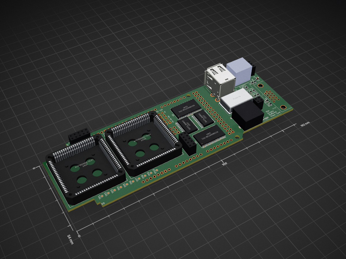
4 layers162 × 54 mmVGA SRAM SHIELD 1508, the printed circuit board in 3D

VGA SRAM SHIELD 1508

levvayner/VGA_PLD4

If choosing the former, follow Atmel's instructions using the included .pld files. If chosing the latter, you can open the workspace and you will see both projects. You can build and deploy the projects right from Code!

Size
162 × 54 mm
Copper layers
4
Thickness
1.6 mm
Parts
52
Nets
248
Pads
570
Tracks, vias
0, 0
Routed
Not yet
KiCad
KiCad 8.0 (file 20240108)
Created
2 Nov 2024
Updated
7 Nov 2025

Overview

VGA SRAM SHIELD 1508 is an open-source printed circuit board by levvayner, from the levvayner/VGA_PLD repository on GitHub. It is a 4-layer board of 162 × 54 mm with 52 parts on 248 nets.

It is built around the ATF1508AS-10JU84 and 74HC245D. Its parts include 12 resistors, 9 connectors, 8 ICs, 1 capacitor and 1 crystal. It belongs with the FPGA and CPLD boards of this library.

Main components

2

README

README.md

VGA Video Card

This project uses TTL components and 2 GALs to create a video card. There are several parts to the entire development system to aid in development and troubleshooting. Another repository for code that is used on the Arduino Due can be found at https://github.com/levvayner/SRAM-Console

Parts

  • Hardware Design files in KiCad
  • 2 projects for progamming GAL22V10C PLDs
  • Application used to refine and upload images to the Arduino Due
  • Timing and other documentation
  • Firmware for the Arduino Due to host the video card (https://github.com/levvayner/SRAM-Console)

Getting Started

Prerequisites

Schematics

KiCad software - available for free @ https://www.kicad.org/

Programmable Logic Devices

This can be done with the official Atmel software (https://www.microchip.com/en-us/products/fpgas-and-plds/spld-cplds/pld-design-resources) on windows and using their programmer. An alternative approach is to use a cheap progammer like the TL866+ and using Microsoft Code with the VS Cupl extension. -http://www.xgecu.com/en/TL866_main.html -https://marketplace.visualstudio.com/items?itemName=VaynerSystems.VS-Cupl

If choosing the former, follow Atmel's instructions using the included .pld files. If chosing the latter, you can open the workspace and you will see both projects. You can build and deploy the projects right from Code!

You will need to download the Atmel Wincupl progam either way. If you chose to use VS code, you will also need to download and install minipro. More instructions about requirements can be found in the VS Cupl repo https://github.com/levvayner/ATF15xx-cupl

Microcontroller

The project uses an Arduino Due uC. The device is low cost, offers a great deal of pins, and has a low price point.

Another device like the Arduino MEGA may suffice. Install Microsoft's Code and install the Platform IO extension. The project can be found here: https://github.com/levvayner/SRAM-Console

Building the hardware

You can use a breadboard and follow the schematic to build the circuit. First the clock and counters are wired. Then the PLDs are wired to execute combinatory logic to determine timing signals like V-SYNC, H-SYNC, and others like when the screen is not displaying, marking it safe to write to RAM.

The components used in the schematic are available in the KiCad project's output folder. Currently they are

ComponentSource
Arduino Duehttps://docs.arduino.cc/hardware/due
Capactitor (0805) 560 pfebay, mouser, digikey
Capacitor Tantalumebay, mouser, digikey
2.54mm pinsebay, mouser, digikey
DSUB 15 pin VGA connectorebay, mouser, digikey
USB type A connectorebay, mouser, digikey
Resistors (0805)ebay, mouser, digikey
K6X8008T2B-TF55https://www.alldatasheet.com/datasheet-pdf/download/85484/SAMSUNG/K6X8008C2B-TF55.html
74HC245Debay, mouser, digikey
74HC161Debay, mouser, digikey
74HC32Debay, mouser, digikey
74HC08Debay, mouser, digikey
74HC00Debay, mouser, digikey
74HC14Debay, mouser, digikey
GAL22V10ebay, mouser, digikey
16MHz Full can oscillatorebay, mouser, digikey

GALs

The programmable logic devices are not absolutely required. They can be replaced by inverters and a few logic gates to determine when a counter should trigger a signal (e.g. h-sync at count 603) and use the counter inputs to determine if that number is reached. Several flip flops can be used for storing the state e.g. store v-sync bit at frame 610, clear at 620. However you may want to change timings or the clock speed to accomplish a different resolution or pixel density. It is much easier to reprogram the GALS to change timing than to re-wire these logic gates. If you have finalized your design, chaning to logic gates and flip flops is recommended. Even better you can use a magnitude comperator instead of a collection of logic gates.

To progam the gals, you may need to erase the chip. Some chips come locked, and the programmer software from XGECU has an option to clear it. If your changes don't seem to take affect after programming, use their software to make sure the chip is not locked.

There are two projects included. One is used for the horizontal timing, the other for vertical.

There is VGA_SINGLE_PLD project that can use an ATF1504AS instead of these two, but it has not been verified.

Arduino

The project VGA Controller can be used to interface with and develop the video card further. It has functionality to connect to the controller from its serial port, or connect a PS/2 keyboard (experimental)

Roadmap

  • Add PS/2 mouse support
  • Add second SRAM chip to expand data bus to 16 bit
  • Add second SRAM chip to round-robin 2 chips between controller and video output, allowing for controller to read/write to SRAM without interfering with the VGA rendering process.
Parts

52
QtyValueFootprintReferences
20TestPointTestPoint:TestPoint_Pad_D1.0mmTP1, TP2, TP3, TP4, TP5, TP10, TP11, TP12, TP13, TP14, TP15, TP16, TP17, TP18, TP19, TP20 +4
3R470Resistor_SMD:R_0805_2012MetricR4, R7, R10
274HC245Package_SO:SOP-20_7.5x12.8mm_P1.27mmU7, U8
2ATF1508AS-10JU84PLCC-84:PLCC84ATU2, U4
2K6X8008T2B-TF55Package_SO:TSOP-II-44_10.16x18.41mm_P0.8mmU5, U6
2R1.8KResistor_SMD:R_0805_2012MetricR5, R9
2R100Resistor_SMD:R_0805_2012MetricR11, R12
14.7nFCapacitor_SMD:C_0805_2012MetricC1
1ANALOGConnector_PinSocket_2.54mm:PinSocket_2x05_P2.54mm_VerticalJ2
1AUDIOConnector_PinSocket_2.54mm:PinSocket_1x03_P2.54mm_VerticalJ7
1Arduino_Due_Shieldarduino-library:Arduino_Due_ShieldA1
1DATA_BANK1Package_SO:SOP-20_7.5x12.8mm_P1.27mmU1
1DATA_BANK2Package_SO:SOP-20_7.5x12.8mm_P1.27mmU3
1GND PWRConnector_PinSocket_2.54mm:PinSocket_2x02_P2.54mm_VerticalJ4
1HORZ ISPConnector_PinSocket_2.54mm:PinSocket_2x05_P2.54mm_VerticalJ5
1Micro_SD_CardSDCard:J_SD_Card-micro_socket_AJ6
1Mini-DIN-6Libraries:mini-DIN 6J3
1R1.2KResistor_SMD:R_0805_2012MetricR6
1R2.2KResistor_SMD:R_0805_2012MetricR8
1R3.9KResistor_SMD:R_0805_2012MetricR2
1R490KResistor_SMD:R_0805_2012MetricR1
1R800Resistor_SMD:R_0805_2012MetricR3
1TCXO-14Oscillator:Oscillator_DIP-14X1
1USB_A_StackedConnector_USB:USB_A_CUI_UJ2-ADH-TH_Horizontal_StackedJ1
1VERT ISPConnector_PinSocket_2.54mm:PinSocket_2x05_P2.54mm_VerticalJ8
1VGA D-SUB15Connector_Dsub:DSUB-15-HD_Female_Horizontal_P2.29x1.90mm_EdgePinOffset3.03mm_Housed_MountingHolesOffset4.94mmJ9

More from levvayner/VGA_PLD

4
  • 4 layers86.5 × 75 mmVGA SRAM COMP, the printed circuit board in 3D

    VGA SRAM COMP

    levvayner/VGA_PLD

    If choosing the former, follow Atmel's instructions using the included .pld files. If chosing the latter, you can open the workspace and you will see both projects. You can build and deploy the projects right from Code!

    51 parts4
  • 4 layers97.5 × 53.4 mmVGA SRAM Shield, the printed circuit board in 3D

    VGA SRAM Shield

    levvayner/VGA_PLD

    If choosing the former, follow Atmel's instructions using the included .pld files. If chosing the latter, you can open the workspace and you will see both projects. You can build and deploy the projects right from Code!

    51 parts4
  • 4 layers97.5 × 53.4 mmVGA SRAM Shield, the printed circuit board in 3D

    VGA SRAM Shield

    levvayner/VGA_PLD

    If choosing the former, follow Atmel's instructions using the included .pld files. If chosing the latter, you can open the workspace and you will see both projects. You can build and deploy the projects right from Code!

    48 parts4
  • 6 layers125 × 53.5 mmVGA SRAM SHUIELD DOUBLE BUFFER, the printed circuit board in 3D

    VGA SRAM SHUIELD DOUBLE BUFFER

    levvayner/VGA_PLD

    If choosing the former, follow Atmel's instructions using the included .pld files. If chosing the latter, you can open the workspace and you will see both projects. You can build and deploy the projects right from Code!

    45 parts4

Similar boards

  • 2 layers54.2 × 86.6 mmAtmel ATF15XX Programming Adapter, the printed circuit board in 3D

    Atmel ATF15XX Programming Adapter

    djtersteegc/Atmel-ATF15XX-Programming-Hardware

    Programmer and PLCC adapter boards for the Atmel ATF15XX family CPLD's. Adapter boards are also compatible with older Altera Max7000's devices with similar pinouts.

    30 parts6
  • 2 layers100 × 100 mmSystemBoardPLCC, the printed circuit board in 3D

    SystemBoardPLCC

    transistorfet/retroverse

    A collection of VME-based hardware and software for modular computers

    37 parts17
  • 2 layers245.1 × 160 mm8-Bit CPU 32k, the printed circuit board in 3D

    8-Bit CPU 32k

    slu4coder/Minimal-64x4-Home-Computer

    My DIY TTL home computer with VGA and PS/2 and 4x the processing power of a Commodore C64 or Apple II.

    139 parts326
  • 2 layers191.8 × 121.3 mm8-Bit CPU 32k, the printed circuit board in 3D

    8-Bit CPU 32k

    slu4coder/Minimal-UART-Computer-1-2

    Legacy: Version 1 and 2 of my TTL-only CPU featuring UART I/O, an expansion port, 512KB SSD at up to 10MHz clock speed

    109 parts184
  • 4 layers215 × 150 mmMackerel-30-proto, the printed circuit board in 3D

    Mackerel-30-proto

    crmaykish/mackerel-68k

    A series of single-board Motorola 68k computers with support for modern Linux

    133 parts96MIT
  • 2 layers306.1 × 130.2 mm8-Bit CPU 32k, the printed circuit board in 3D

    8-Bit CPU 32k

    slu4coder/Minimal-64-Home-Computer

    Legacy: Full TTL-only home computer with VGA and PS/2 and twice the processing power of a Commodore 64

    132 parts94
  • 2 layers36.8 × 27.9 mmPixelvationEngine V01, the printed circuit board in 3D

    PixelvationEngine V01

    Pixelvation/Pixelvation

    This GitHub repository is the current home of Pixelvation and will be updated whenever there's some significant new development.

    30 parts69
  • 4 layers188.9 × 92 mmMegaCD, the printed circuit board in 3D

    MegaCD

    Board-Folk/MegaCD-Main-BD

    Reproductions of main board PCBs for Sega's Mega CD/Sega CD add-on for the Mega Drive/Genesis console.

    132 parts60

Questions

How big is the VGA SRAM SHIELD 1508 PCB?

It measures 162 × 54 mm and has 4 copper layers, 1.6 mm thick.

What parts does the VGA SRAM SHIELD 1508 use?

52 parts, built around the ATF1508AS-10JU84 and 74HC245D. The full list of its parts is on this page, with links to each part's symbol and footprint where PCBKit's library has them.

Where can I download the VGA SRAM SHIELD 1508 KiCad files?

From the levvayner/VGA_PLD repository on GitHub, at the commit this page was made from: the board is VGA_SRAM_SHIELD_1508/VGA_SRAM_SHIELD_1508.kicad_pcb and its schematic DUE_SHIELD_VGA_DUAL_BUFFER_OPTIMIZED/DUE_SHIELD_VGA_DUAL_BUFFER_OPTIMIZED.kicad_sch. PCBKit opens the board in the browser, with nothing to install.

Can I use the VGA SRAM SHIELD 1508 design in my own project?

Its repository states no licence, so its author keeps all rights: ask levvayner before reusing the design.