2 layers56 × 32 mm
Ascom flat panel
letelescope/ascom-flat-panel
Open source ASCOM and INDI driven automated flat panel for astrophotography
15 parts2MIT

 letelescope/ascom-flat-panel2
Open source ASCOM and INDI driven automated flat panel for astrophotography
Ascom flat panel is an open-source printed circuit board by letelescope, from the letelescope/ascom-flat-panel repository on GitHub, published under the MIT licence. It is a 2-layer board of 56.5 × 74 mm with 17 parts on 32 nets, routed with 64 tracks and 0 vias.
It is built around the TLC272CD, IRLZ34N and TIP120. Its parts include 4 resistors, 3 ICs, 2 capacitors, 2 diodes and 2 transistors.










Open source ASCOM and INDI driven automated flat panel for astrophotography.
⚠ DISCLAIMER
This project is still very much work in progress. None of it is likely/expected to work at this stage !
This project is an open source initiative, under the MIT license, by Le Telescope. This is the v2 of a fully automated and drivable motorized flat panel/dust cap. The device is nicknamed FFFP. Don't ask why! If you still want to know, see the misc. section of this readme.
This project should contain all you need to build your own ASCOM and/or INDI driven Flat Panel.
This project, the protocol, the implementation of both the ASCOM driver and the firmware, the electronics and the 3D models are heavily inspired by the the work of Dark Sky Geek. And more precisely:
Kudos to him.
The Pulse Width Modulation (PWM), used to control the panel brightness, implementation is heavily inspired, or more accurately shamelessly ripped, from the work of Khoih Hoang and more precisely SAMD_PWM.
Kudos to him too.
Finally te INDI driver architecture follows very closely the official Gemini Flat Panel as well as teh Flip Flat implemtentations.
In this scenario a flat panel is made of two things
The cover is motorized using a servo motor and held in open/close positions using simple magnets. The lightpanel is made
This "electronico-mechanical" assembly is controlled via a SAMD21 based board with a custom firmware within a custom PCB. The SAMD21 is particullarly suited because:
One can connect and send commands to the flat-panel using Serial (COM Port) over USB. When plugged in the device will be recognized by windows/linux as a COM device.
Finally this is driven by ASCOM/INDI, such that one can fully automate taking flats following the acquisition sessions of our beloved night sky targets.
⚠ DISCLAIMER
This project is built around the Seeeduino XIAO board that uses the ATSAMD21G18A-MU chip. This is the only board that we tested. This may work on other boards that uses these SAMD21 chips, but this may need some rework on the firware, the PCB layout and the mechanical assembly.
Now that we have the big picture let's get real and build the thing !
[INSERT HERE SOME PHOTOS]
Very few pre-requisites are necessary in order to build the flat panel. More precisely one will need to:
And that's it ! For instance you won't need software developpement skills as both the driver and the firmware are usable as is. Moreover, the ASCOM driver installer is already pre-compiled and made available to the download. Unfortunaltely one cannot make an "installer" for the arduino firware. Yet using PlaterfomIO to upload the firmware is a matter of three clicks.
We chose PlatformIO instead of ArduinoIDE due to recent concerns about Arduino's Open Source commitment under Qualcomm, and ,icing on the cake, PlatformIO provides superior dependency and library management.
[TODO] ADD BILL OF MATERIAL
We heavily use the git version control "tags" to label released versions. We also leverage the "GitHub releases" that add the possibility to pin "binaries" (ie anything we want PCB layouts, Driver installers, mechanincal assembly 3D printer files,...) on "tagged" versions.
When we deem a version is "usable" we tag it, ie we freeze this repository at a particular "commit", and create a release out of it.
To access the various releases just got the releases page of this repository.
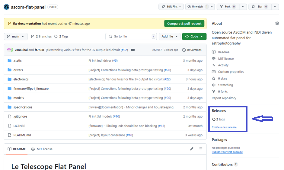
And choose the release you want. The latest should be the "better".
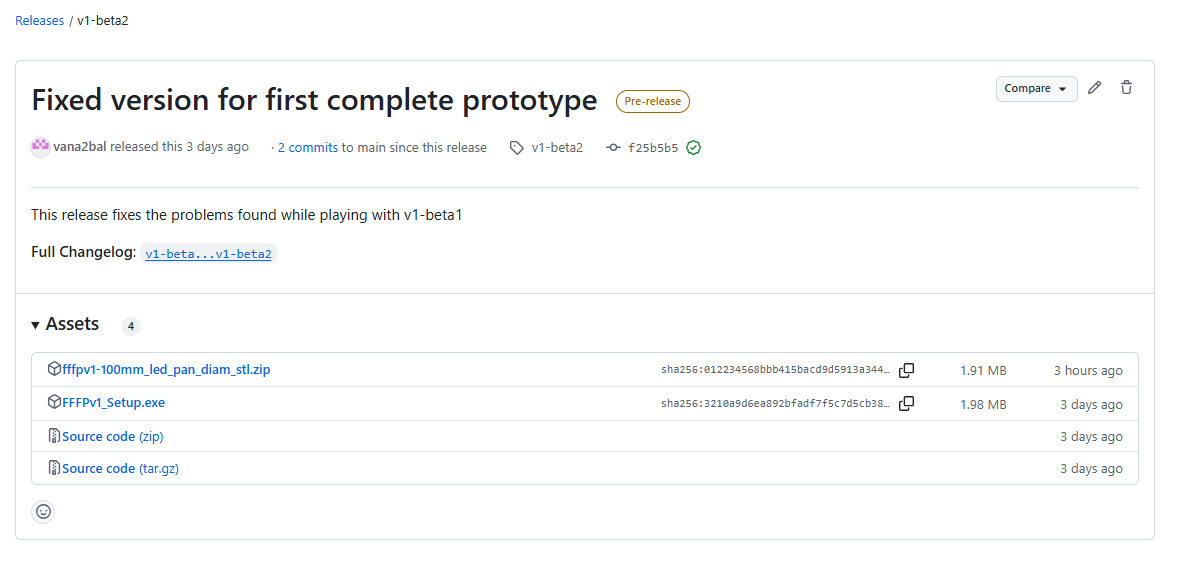
We recommend that you use one of these released version as they are coherent and tested. Be careful some release are labelled "pre-release" and should be used with caution. Those are developpement, beta and alpha version. Use it at you own risk like all the material on this repository. But even more in this case :D.
In the same spirit, we do not recommend you use the "head" of the main branch (or any other branch) of this repository as this is work in progress and hence is not guaranteed to be stable or even usable...
If you already have an FFFPV1, please note that both drivers and firmware should be backward compatible. You can use the latest version of both the ASCOM driver with your FFFPV1 without any issue and vice-versa: upload the new firmware on your FFFPV1 device and still use the legacy v1 driver. Yet we recommend you use the latest version of the driver, the firmware, the electronic circuit and the assembly as they all have been improved coherently.
We provide three options for the electronic circuit. The difference is made on wether you want to use a led panel or a EL panel (You may not have the choice, as LED panels are restricted to smaller diameters).
This is certainely the "go to" solution, as this allows for a slicker and ligther mechanical assembly. Ans the electronics are not that much more difficut.
⚠ WARNING
The choice of Pin AO for DAC is not random. This is the only one on the Seeeduino XIAO (and SAM-D21 chips) capable to produce proper DAC. Please see.
The Pins "5,6,7" of the Seeeduino XIAO are used for power control, position control and servo feedback:
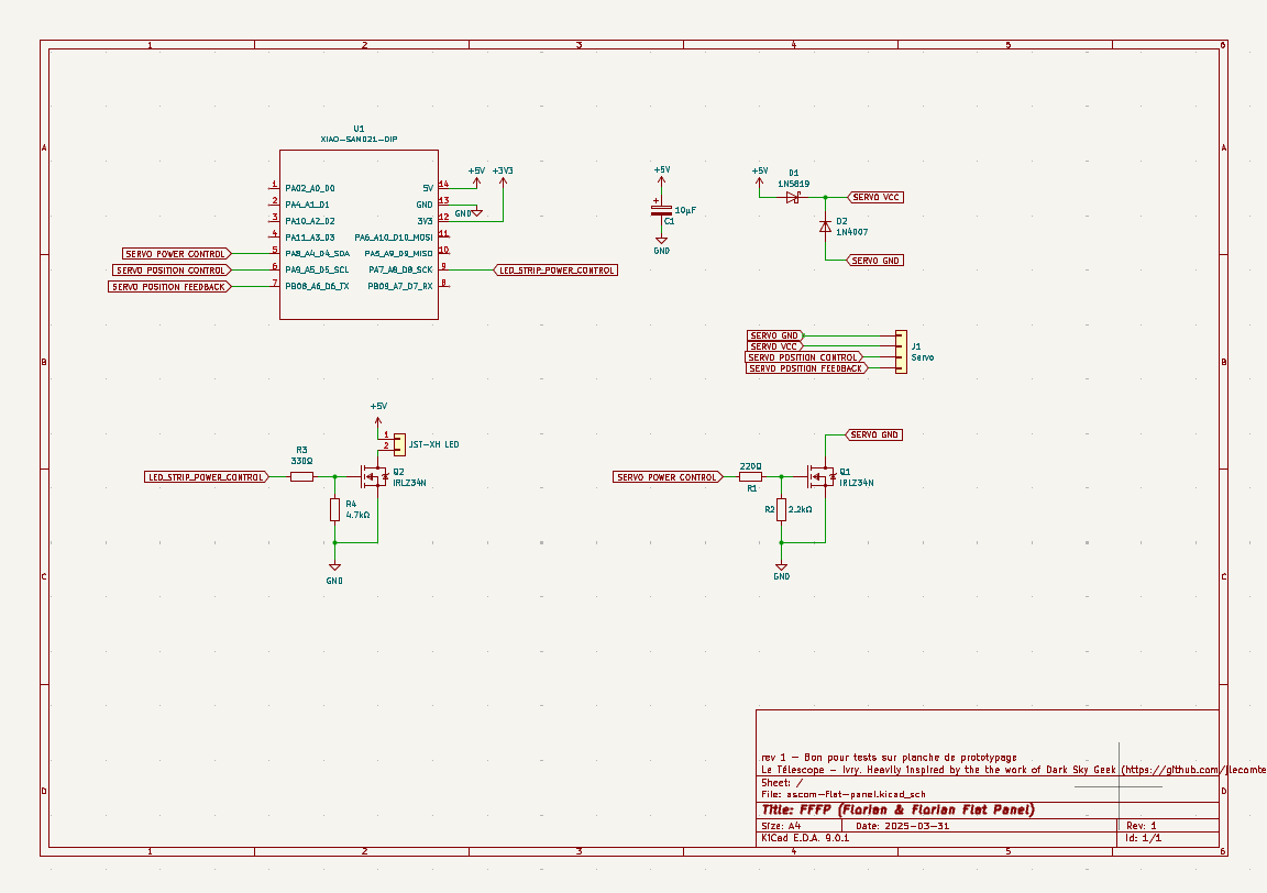
Servo VCC and Servo ground are decoupled using diodes.
+12V and +5V are decoupled from ground using 10μF capacitors. It acts both as
This should be the go solution for most setups. Yet if you setup si particularly slow you may want to check the led versions.
Here is the schematics for this option
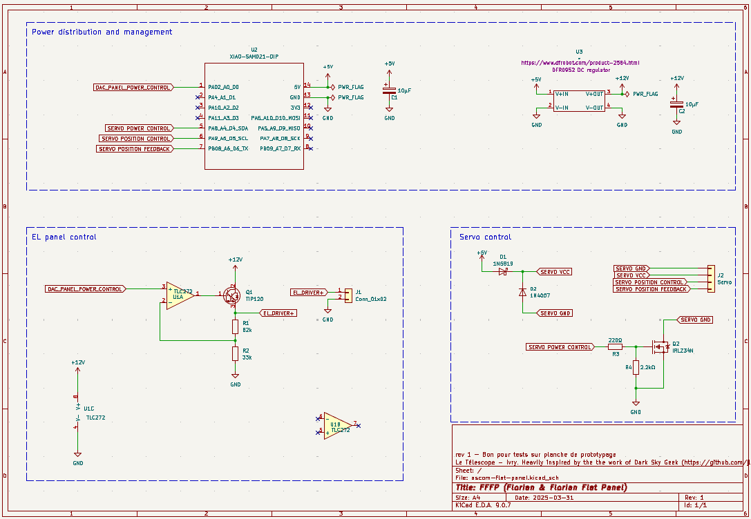
There are two options regarding the tension value used to power the LEDs: either +3V3 or +5V. But appart from that the two circuits share the same principles:
⚠ WARNING
The choice of Pin 8 for PWM is not random. Not all pins of Seeeduino XIAO (and SAM-D21 chips) are capable to produce high frequency PWM. That's possible with Pin 8 because it use timer counter TCC1 which is 16bits. And If you want to choose another pin please check the documentation first.
The Pins "5,6,7" of the Seeeduino XIAO are used for power control, position control and servo feedback:
Servo VCC and Servo ground are decoupled using diodes.
+5V (and +3V3 if needed) are decoupled from ground using 10μF capacitors. It acts both as
This is best suited for small refractors using fewer LEDs and/or fast optics.
Here is the schematics for this option
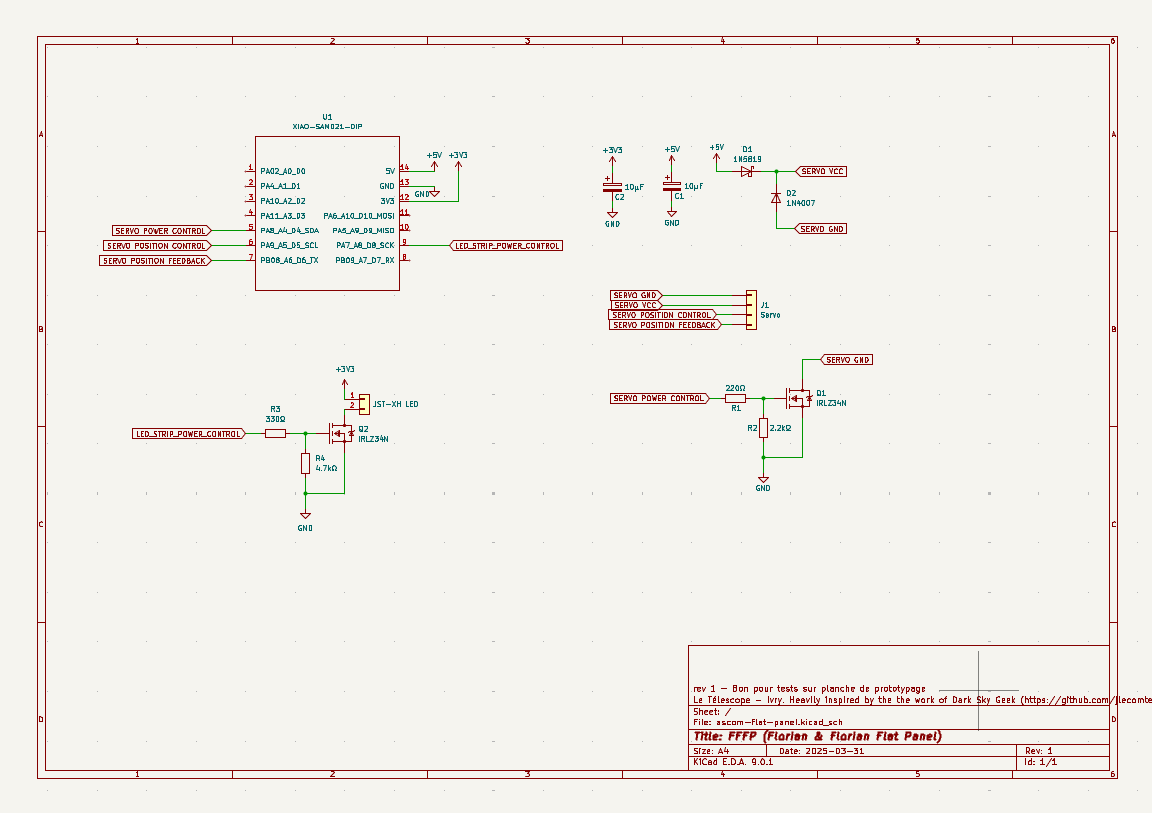
This is best suited for bigger tubes using a larger number of LEDs drawing more current.
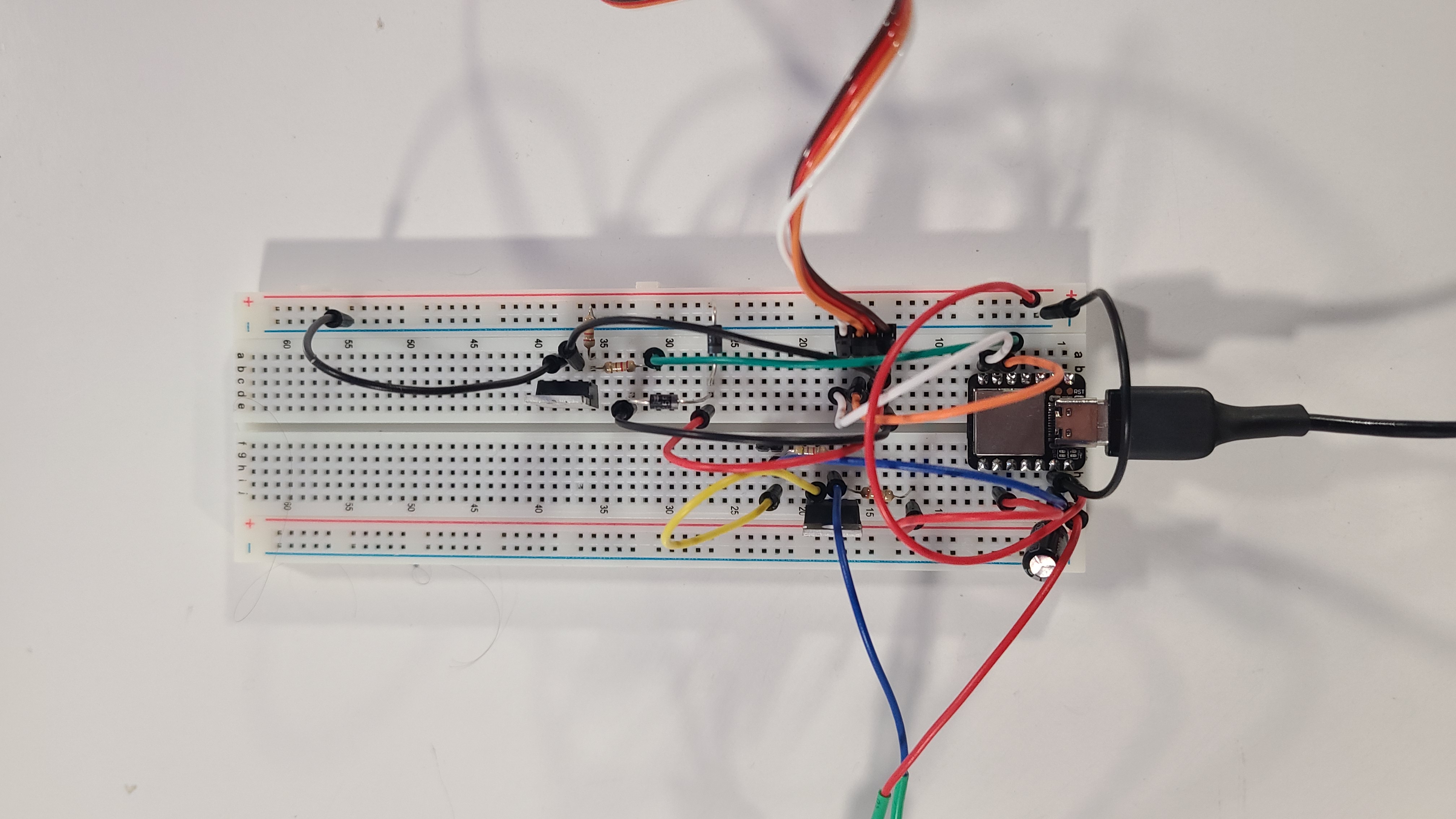
We recommend you prototype the circuit using breadbords first.
Here is and example of what the "+5V" circuit may look like on a breadbord.
 .
We had our PCBs printed by PCBWay. If you do not modify the PCB layout and want to have it printed by PCBWay, you can just download one of the provided zip files that are pinned to the release (fffpv1-electronics-5V-LEDs-pcbway-files.zip or fffpv1-electronics-3V-LEDs-pcbway-files.zip, depending if you intend to use the +5V or +3V3 version).
If you want to modify the PCB layout, you have two options depending on the company you chose to print your PCB :
The firmware needs to be uploaded using Visual Studio Code/PlateformIO . PlateformIO setup section of this documentation to set it.
Open the firmware project from Visula Strudio Code/Plateform-IO.
Connect the board via US.
Select the board.
Click the "arrow" at the bottom to compile and upload the firmware on the board.
The output should look something like:
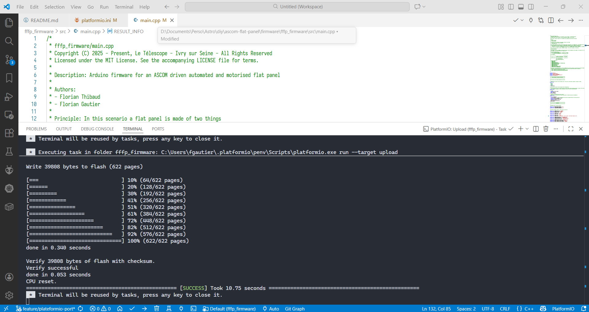
Once the firware is uploaded, do not disconnect the board yet. Still from the Arduino IDE open the "Serial Monitor". Once connected, in the console type:
COMMAND:PINGthe board should answer
RESULT:PONGCongrats! The Seeeduino is ready to act as your flat panel controller !
Moving on to the actual print and build of the assembly.
This repository (and therefore the tagged release version) contains a fully fonctional model. This is made to fit an Askar SQA-55 and uses premade 100mm led panel. It also feature an adapter to fit an Askar 71F.
"Ready to print" STL files are also pinned to the release. Just download the fffpv1-100mm_led_pan_diam_stl.zip archive, unzip it. The archiver files are organized within two folders "Black" and "White". Files in he "black" repository can be printed in the color of your choice, but the one in the "white" folder should be printed using white PLA for better performance. This is especially true for the "spacer/diffuser" that, as its name suggests, helps homogenise the illumination of the panel.
⚠ WARNING The firmware needs to be calibrated.
At first boot the LEDs will flash to indicate that it needs to be calibrated.
⚠ WARNING Disconnect the servo from the mecanical assembly before launching the calibration procedure.
Then from the IDE connect to the board and using the Arduino serial monitor send (type) the "command"
COMMAND:COVER_CALIBRATION_RUNThe device should perform its calibration procedure and reply with
RESULT:COVER_CALIBRATION_RUN@OKOnce it has completed, re-attach the right arm to the servo. The device is now ready to be used.
You can either used the installer to install the ASCOM driver or build it from source. For the sake of simplicity we recommend using the installer.
The installer is pined on each release releases page.
From the wanted release, download the file "FFFP_Setup.exe".
"Double-click" on the downloaded file to launch it.
⚠ WARNING Windows will warn that the publisher is unknown. This is perfectly fine. As buying a verified signing key, is definitely not a priority for us, we could not sign the installer. Yet this is perfectly safe to use it.
Follow the instruction to install and register the driver.
Congrats! You just installed the driver !
To build it from source please check the relevant section of the "developpement documentation".
Once install is complete, one can use the ASCOM profile explorer tool to check that this was installed properly. From the ASCOM profile explorer check that the ASCOM CoverCalibrator Drvier for Le Telescope FFFP is listed in the Cover Calibrators.
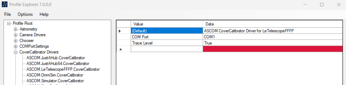
⚠ WARNING INDO driver is NOT functional DO NOT USE IT.
To avoid mass troubleshooting, one can test each component fairly separately. Below are listed some tests that can be used to validate the setup. Going from "unit test" to big-bang integration tests from your favourite acquisition software.
Once the firware is uploaded, one should already have tested that the seeduino was responsive. If not, reconnect the board via USB. From the Arduino IDE, open the "Serial Monitor". Once connected, in the console type:
COMMAND:PINGthe board should answer
RESULT:PONGIf that's not the case, please make sure that you uploaded the (correct version of the) firmware firt.
If that is indeed the case, congrats you are ready to test more "interesting" features of the firmware.
From the "Serial Monitor", in the console type the following command to adjust the LED panel brightness level:
COMMAND:BRIGHTNESS_SET@1024the board should answer in the console
RESULT:BRIGHTNESS_SET@1024In parallel, if it is connected to the board, the light panel should have been turned on. Feel free to change the value (number after the '@') to adjust the brightness. Max allowed value is 2047 and min value is 0.
Use COMMAND:BRIGHTNESS_RESET to switch off the panel.
Congrats the variable light panel is functionnal.
⚠ WARNING To be able to open/close the panel, the panel should be calibrated first. Check the "mechanical assembly" section for the procedure.
When turned on, the panel should be closed. To open it, from the "Serial Monitor", in the console type the following command:
COMMAND:COVER_OPENthe panel should start moving and the board should answer in the console
RESULT:COVER_OPEN@OKOnce open to close it simply type in the consle
COMMAND:COVER_CLOSEthe panel should start moving and the board should answer in the console
RESULT:COVER_CLOSE@OKFinally at any given time, to know the status of the mecanical panel type
COMMAND:COVER_GET_STATEthe panel should start moving and the board should answer in the console
RESULT:COVER_GET@{panel.cover}where panel.cover is string human readable translation of the current cover state. Possible values are in [OPEN, OPENING, CLOSING,];
Congrats the motorized cover is functionnal.
After install completion, one should already have used the ASCOM profile explorer tool to check that this was installed properly. If that's not the case from the ASCOM profile explorer check that the ASCOM CoverCalibrator Drvier for Le Telescope FFFP is listed in the Cover Calibrators.
Then check that the driver is instiable using the ASCOM diagnostic tools
a. Select the "Cover Calibrator" device type and elect the "FFPV1 Cover Calibrator"
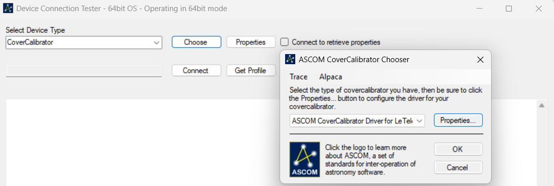
b. Find and configure the "properties" of the driver
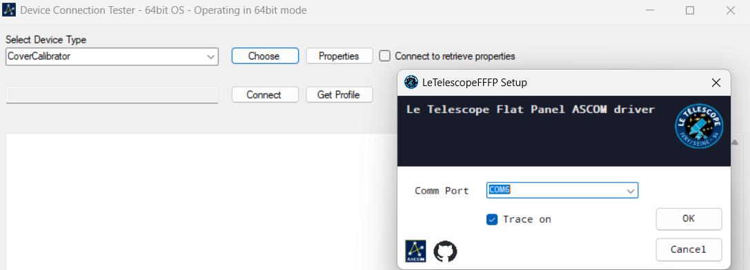
b. Connect to the driver. Expect nothing much to happen.
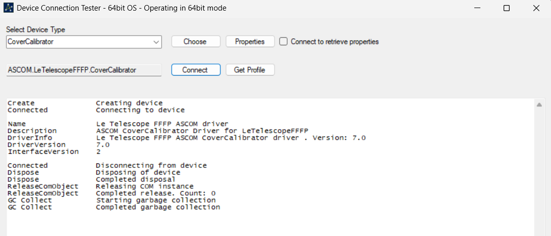
Congrats the driver seems to work as expected !
Great ! If you read this, at this stage, the firware, the driver and the mecanical assembly should work, or at least one should be confident enough that they are working. Let's make the final test (and the only one relevant in fact). Let's take some flats from N.I.N.A.
The FFFP should be now be fully usable and drivable from N.I.N.A.
Let's connect to the flat panel.
In the equipment tab, from the flat panel section:
Select the ASCOM CoverCalibrator Drvier for Le Telescope FFFP.
Click the gear icon and select the correct COM Port.
Hit OK to save the configuration.
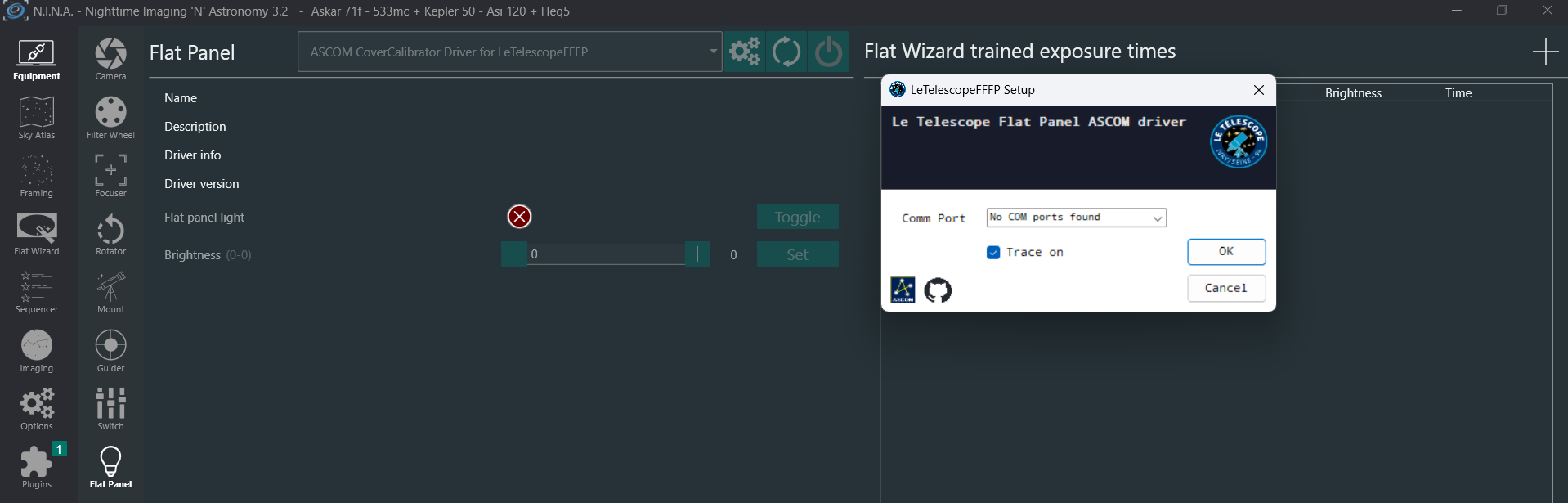
Click the "power" button to connect to the flat panel.
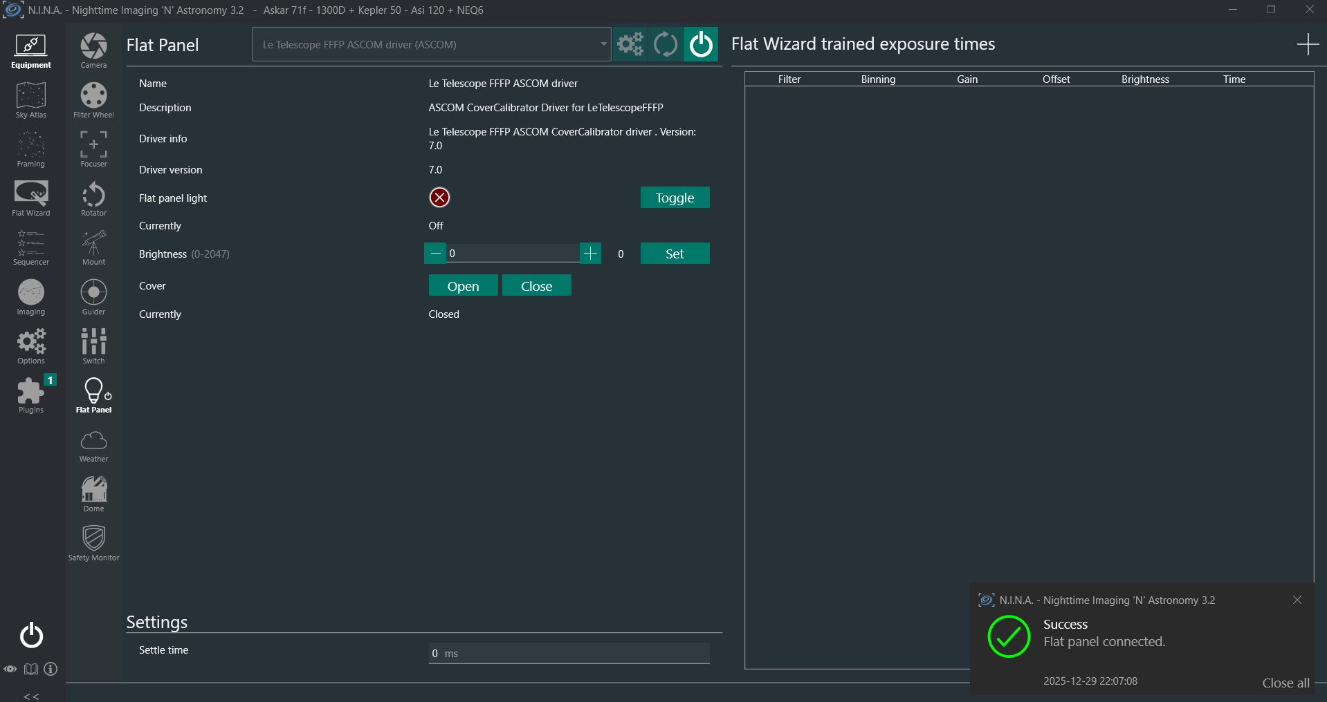
From there you can turn on and off the panel, set the wanted brightness and/or open/close the cover.
Let's now use the N.I.N.A smart flats capabilities to automate flat frames recording.
In this scenario a flat panel is made of two things
The firmware updates the state of the flat panel upon instructions of the (ASCOM or INDI) driver. The communication protocol is serial based. The serial connection is established via USB. Here is a a summary of the protocol
The driver emmits and the firmware handles the incoming "COMMAND" messages. This kind of message is stuctured as
COMMAND:NAME[@ARGS] where NAME is [A-Z_]+ and ARGS may be optional or mandatory and their nature may depend on the command.The firmware then responds with
RESULT:CMD_NAME@VALUE if operation succeededERROR:ERR_MESSAGE@DETAILS if anything went wrongIn a nutshell
 -----------------                           ------------
|                 |                         |            |
|      Driver     | COMMAND:CMD_NAME[@ARGS] | Flat Panel |
| (ASCOM or INDI) | --------------------->  | (firmware) |
|                 | <---------------------  |            |
 -----------------  RESULT:CMD_NAME@VALUE    ------------
                            or
                    ERROR:ERR_MESSAGE@DETAILS
More details on this protocol are provided in protocol.md
The firware is entirely buildable and uploadable using the Arduino IDE
Using PlateformIO IDE, open the project
Click "PlateformIO: Build" to compile the firmware. The output should be something like
Processing seeed_xiao (platform: atmelsam; board: seeed_xiao; framework: arduino)
--------------------------------------------------------------------------------------------------------------------------------------------------
Verbose mode can be enabled via `-v, --verbose` option
CONFIGURATION: https://docs.platformio.org/page/boards/atmelsam/seeed_xiao.html
PLATFORM: Atmel SAM (8.3.0) > Seeeduino XIAO
HARDWARE: SAMD21G18A 48MHz, 32KB RAM, 256KB Flash
DEBUG: Current (atmel-ice) External (atmel-ice, blackmagic, jlink)
PACKAGES:
 - framework-arduino-samd-seeed @ 1.8.5
 - framework-cmsis @ 2.50400.181126 (5.4.0)
 - framework-cmsis-atmel @ 1.2.2
 - toolchain-gccarmnoneeabi @ 1.70201.0 (7.2.1)
LDF: Library Dependency Finder -> https://bit.ly/configure-pio-ldf
LDF Modes: Finder ~ chain, Compatibility ~ soft
Found 20 compatible libraries
Scanning dependencies...
Dependency Graph
|-- Servo @ 1.3.0
|-- Adafruit SleepyDog Library @ 1.6.5
|-- FF_Flat_Panel
|-- FlashStorage @ 0.5.0
|-- SAMD21_PWM
Building in release mode
Compiling .pio\build\seeed_xiao\src\main.cpp.oDon't worry to much about the warnings. Those are only warnings and can be safely igonered c.f. arduino forum and adafruit forum .
Connect the Seeeduino and "PlateformIO: Build"to test it
The firmware needs to be calibrated. At first boot the leds will flash to indicate that it needs to be calibrated.
WARNING Disconnect the servo from the mecanical assembly before launching the calibration procedure.
Then from the IDE connect to the board and using the Arduino serial monitor send (type) the "command"
COMMAND:COVER_CALIBRATION_RUNThe device should perform its calibration procedure and reply with
RESULT:COVER_CALIBRATION_RUN@OKOnce it has completed, re-attach the right arm to the servo. The device is now ready to be used.
The ASCOM driver is a C# .Net project that have been first created using the ASCOM 6 Visual Studio 2022 templates. Hence we recommend using Visual Studio 2022 when building it. Feel free to change this procedure to match your tooling.
Open the "solution" from Visual Studio 2022
Compile the project using "Ctrl + Shift + B". The result in the console should look something like
Génération démarrée à 14:12...
1>------ Début de la génération : Projet : ASCOM_7_Driver, Configuration : Debug Any CPU ------
1>  ASCOM_6_Driver -> D:\Documents\Perso\Astro\diy\ascom-flat-panel\ASCOM_drivers\ASCOM_7_Driver\bin\Debug\ASCOM.LeTelescopeFFFPV1.exe
========== Build : 1 réussite(s), 0 échec(s), 0 à jour, 0 ignorée(s) ==========
========== Build s’est terminée à 14:12 et a duré 10,405 secondes ==========
The first time you compile the server you must "register it" on the ASCOM plateform. Open an "elevated" command prompt (with admin priviledges) at the folder where the local server executable is located. Run the local server exe with the /regserver parameter which will create the entry that appears in the ASCOM Chooser.
.\ASCOM.LeTelescopeFFFP.exe /regserver*This registration only needs to be done once.
You can now launch the driver from any ASCOM client, e.g. N.I.N.A or the ASCOM Diagnostic tool
As of N.I.N.A 3.1.HF2, the "ASCOM device instance reference " is not disposed when connection failed. In our setup this may happen if the flat panel is not connected to the PC. In this scenario, the connection will fail, but a "driver process" will hang, waiting for N.I.N.A to dispose of the reference.
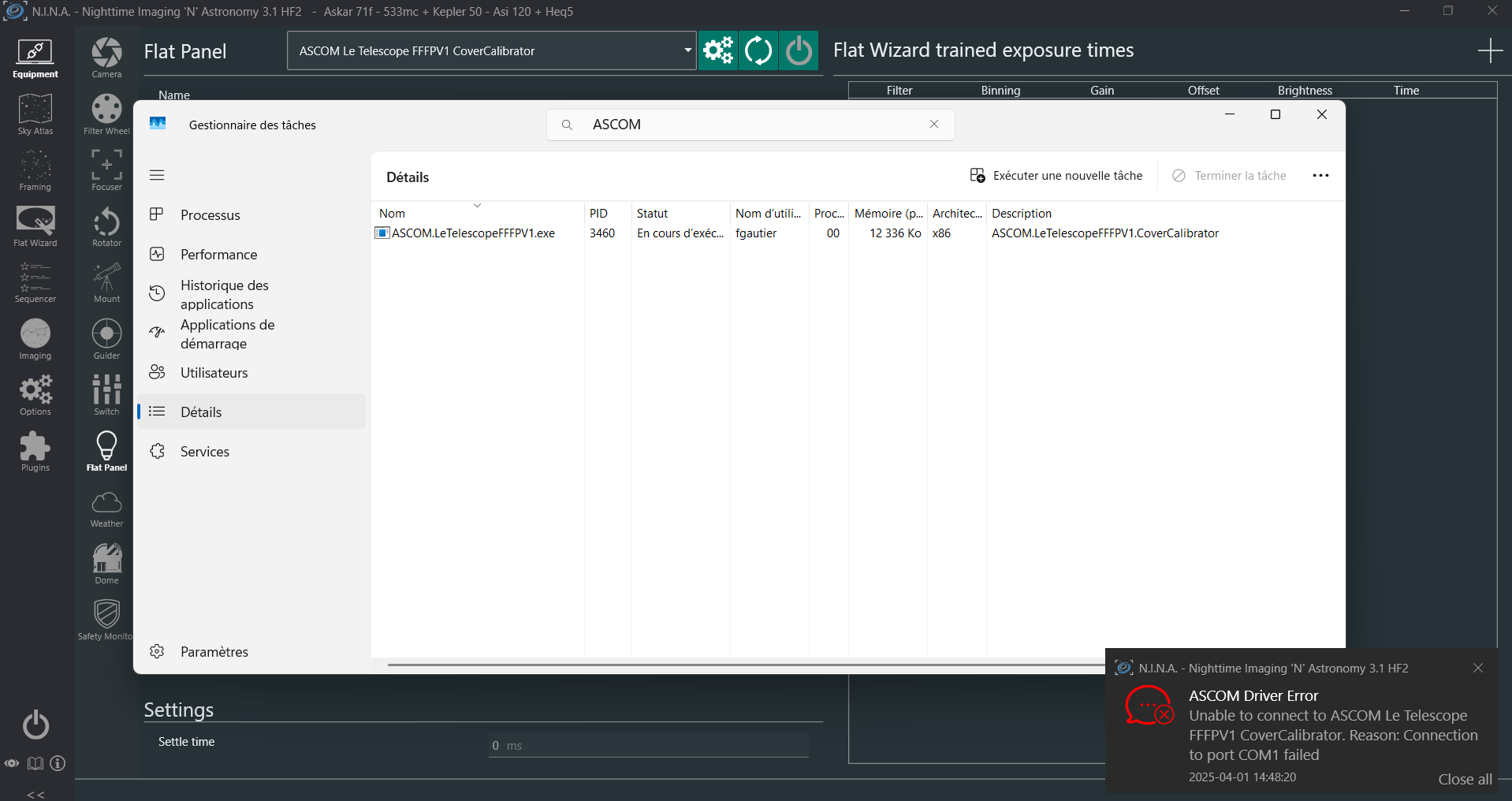
This is a known bug c.f. nina-issue-1378 and ascom developers group thread.
If this happens and some weird side effect happen on reconnection. Just disconnect from the device. Kill the dangling process in the task manager. And reconnect.
The indi driver is in its really early developement phase. It should no be used for anything else but developement.
in the indi directory, from VSCode integrated terminal or anyother terminal run
mkdir -p build
cd build
cmake -DCMAKE_INSTALL_PREFIX=/usr -DCMAKE_BUILD_TYPE=Debug ../
make
sudo make install
or
./make-install.shThe output should be something along the lines of:
-- The C compiler identification is GNU 13.3.0
-- The CXX compiler identification is GNU 13.3.0
-- Detecting C compiler ABI info
-- Detecting C compiler ABI info - done
-- Check for working C compiler: /usr/bin/cc - skipped
-- Detecting C compile features
-- Detecting C compile features - done
-- Detecting CXX compiler ABI info
-- Detecting CXX compiler ABI info - done
-- Check for working CXX compiler: /usr/bin/c++ - skipped
-- Detecting CXX compile features
-- Detecting CXX compile features - done
-- Found INDI: /usr/lib/x86_64-linux-gnu/libindidriver.so;/usr/lib/x86_64-linux-gnu/libindiAlignmentDriver.so (found version "2.1.9")
-- Found NOVA: /usr/lib/x86_64-linux-gnu/libnova.so
-- Found ZLIB: /usr/lib/x86_64-linux-gnu/libz.so (found version "1.3")
-- Found GSL: /usr/include (found version "2.7.1")
-- Performing Test COMPATIBLE_FORTIFY_SOURCE
-- Performing Test COMPATIBLE_FORTIFY_SOURCE - Success
-- Configuring done (2.3s)
-- Generating done (0.0s)
-- Build files have been written to: /home/florian/documents/diy/ascom-flat-panel/drivers/indi/indi_driver/build
[ 50%] Building CXX object CMakeFiles/indi_letelescope_fffp_flatpanel.dir/indi_letelescope_fffp_flatpanel.cpp.o
[100%] Linking CXX executable indi_letelescope_fffp_flatpanel
[100%] Built target indi_letelescope_fffp_flatpanel| Qty | Value | Footprint | References |
|---|---|---|---|
| 2 | 10µF | Capacitor_THT:C_Radial_D6.3mm_H11.0mm_P2.50mm | C1, C2 |
| 2 | LOGO | LOGO | G***, G*** |
| 1 | 1N4007 | Diode_THT:D_DO-41_SOD81_P10.16mm_Horizontal | D2 |
| 1 | 1N5819 | Diode_THT:D_DO-41_SOD81_P10.16mm_Horizontal | D1 |
| 1 | 2.2kΩ | Resistor_THT:R_Axial_DIN0207_L6.3mm_D2.5mm_P10.16mm_Horizontal | R4 |
| 1 | 220Ω | Resistor_THT:R_Axial_DIN0207_L6.3mm_D2.5mm_P10.16mm_Horizontal | R3 |
| 1 | 33k | Resistor_THT:R_Axial_DIN0207_L6.3mm_D2.5mm_P10.16mm_Horizontal | R2 |
| 1 | 82k | Resistor_THT:R_Axial_DIN0207_L6.3mm_D2.5mm_P10.16mm_Horizontal | R1 |
| 1 | Conn_01x02 | Connector_JST:JST_XH_B2B-XH-A_1x02_P2.50mm_Vertical | El Driver |
| 1 | IRLZ34N | Package_TO_SOT_THT:TO-220-3_Vertical | Q2 |
| 1 | Servo | Connector_PinHeader_2.54mm:PinHeader_1x04_P2.54mm_Vertical | J2 |
| 1 | TIP120 | Package_TO_SOT_THT:TO-220-3_Vertical | Q1 |
| 1 | TLC272 | Package_DIP:DIP-8_W7.62mm | U1 |
| 1 | XIAO-SAMD21-DIP | SEEED_STUDIO:XIAO-SAMD21-DIP | U2 |
| 1 | ~ | CustomFootprints:DFR052 DC regulator | U3 |
It measures 56.5 × 74 mm and has 2 copper layers, 1.6 mm thick.
17 parts, built around the TLC272CD, IRLZ34N and TIP120. The full list of its parts is on this page, with links to each part's symbol and footprint where PCBKit's library has them.
From the letelescope/ascom-flat-panel repository on GitHub, at the commit this page was made from: the board is electronics/fffpv2_el_panel/ascom-flat-panel/ascom-flat-panel.kicad_pcb and its schematic electronics/fffpv1-3V-LEDs/ascom-flat-panel/ascom-flat-panel.kicad_sch. PCBKit opens the board in the browser, with nothing to install.
Its repository publishes it under the MIT licence: you may reuse it on that licence's terms (keep the author's notice, and for a copyleft licence share your changes alike).
letelescope/ascom-flat-panel
Open source ASCOM and INDI driven automated flat panel for astrophotography


CASE-Association/christmas-cards
All CASE christmas cards over the years

GadgetReboot/ATTiny_LFO
Dual low frequency oscillators using ATTiny and MCP4725 DACs

Tinkerforge/distance-us-v2-bricklet-techniker
This repository contains the firmware source code and the hardware design files. The documentation generator configs can be found at https://github.com/Tinkerforge/generators

