
4 layers25 × 59 mm

 leonardoward/lora-development-boards4
RFM95W-915S2 Development Board designed with KiCad
Lora testing board is an open-source printed circuit board by leonardoward, from the leonardoward/lora-development-boards repository on GitHub, published under the Apache-2.0 licence. It is a 2-layer board of 69 × 50 mm with 10 parts on 14 nets, routed with 89 tracks and 0 vias.
It is built around the RFM95W-915S2. Its parts include 4 connectors, 1 capacitor and 1 IC. It belongs with the radio and wireless and microcontroller boards boards of this library.
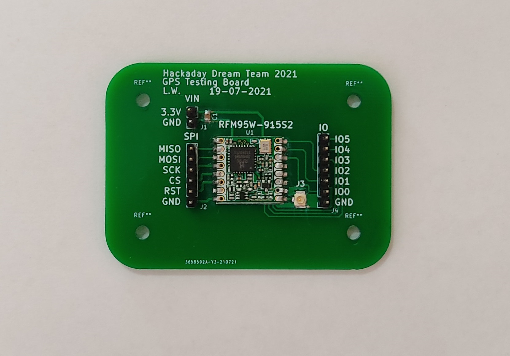
This repository contains the design of a development board for the RFM95W-915S2. The PCB was designed using KiCad.
The RFM95W-915S2 Development board is a PCB that contains a RFM95W LoRa transceiver, a U.FL connector for the external antenna, a decoupling capacitor and a group of headers connected to the different pins of the transceiver. The transceiver can be used as a sender or a receiver.
This is one of the breakout boards made for the EJA "Intelligent Popup Buoy" project (2021 Hackaday Dream Team). LoRa is how the buoy reports its position to a surface gateway, so the RFM95W was proved out on this board before being placed on the EJA M board and the Onboard Gateway. The board is intentionally minimal: transceiver, U.FL antenna connector, one decoupling capacitor, and every useful pin on 2.54 mm headers.
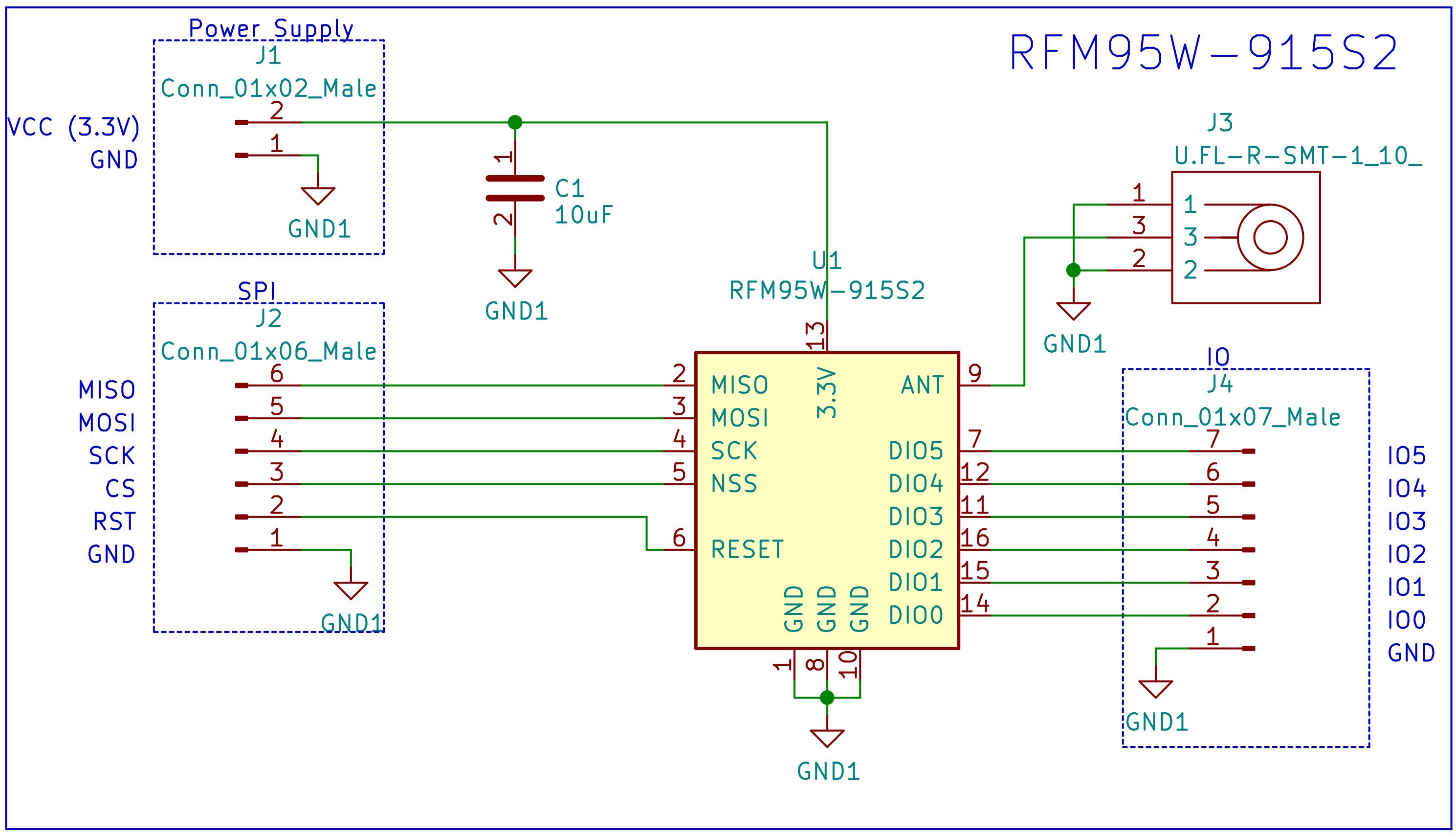
| Reference | Quantity |
|---|---|
| RFM95W-915S2 LoRa™ Transceiver Module 915MHz SMD | 1 |
| 10 µF ±10% 6.3V Ceramic Capacitor 0805 | 1 |
| U.FL (UMCC) Connector Receptacle, Male Pin 50 Ohm SMD | 1 |
| Conn Header 40POS 2.54 | 1 |
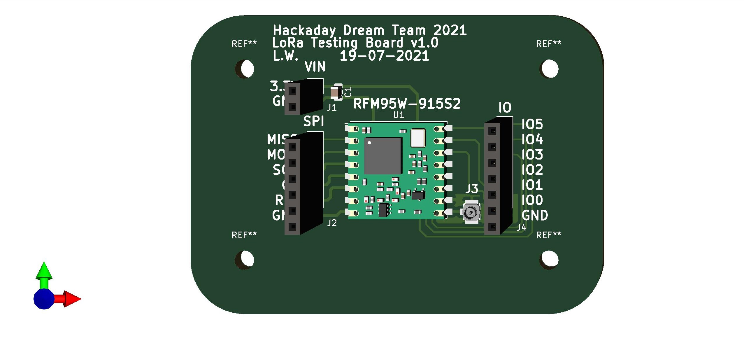
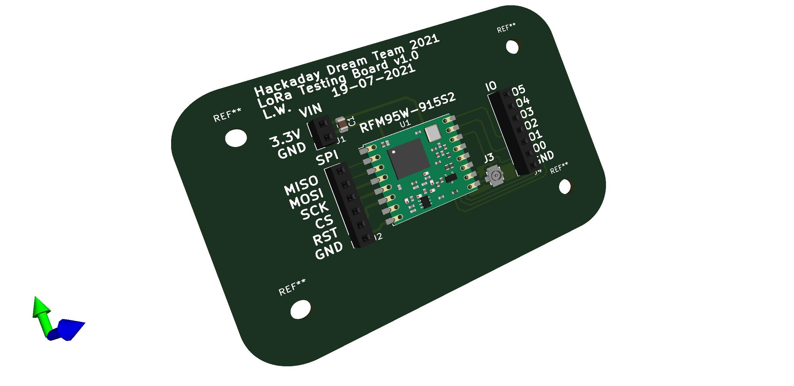
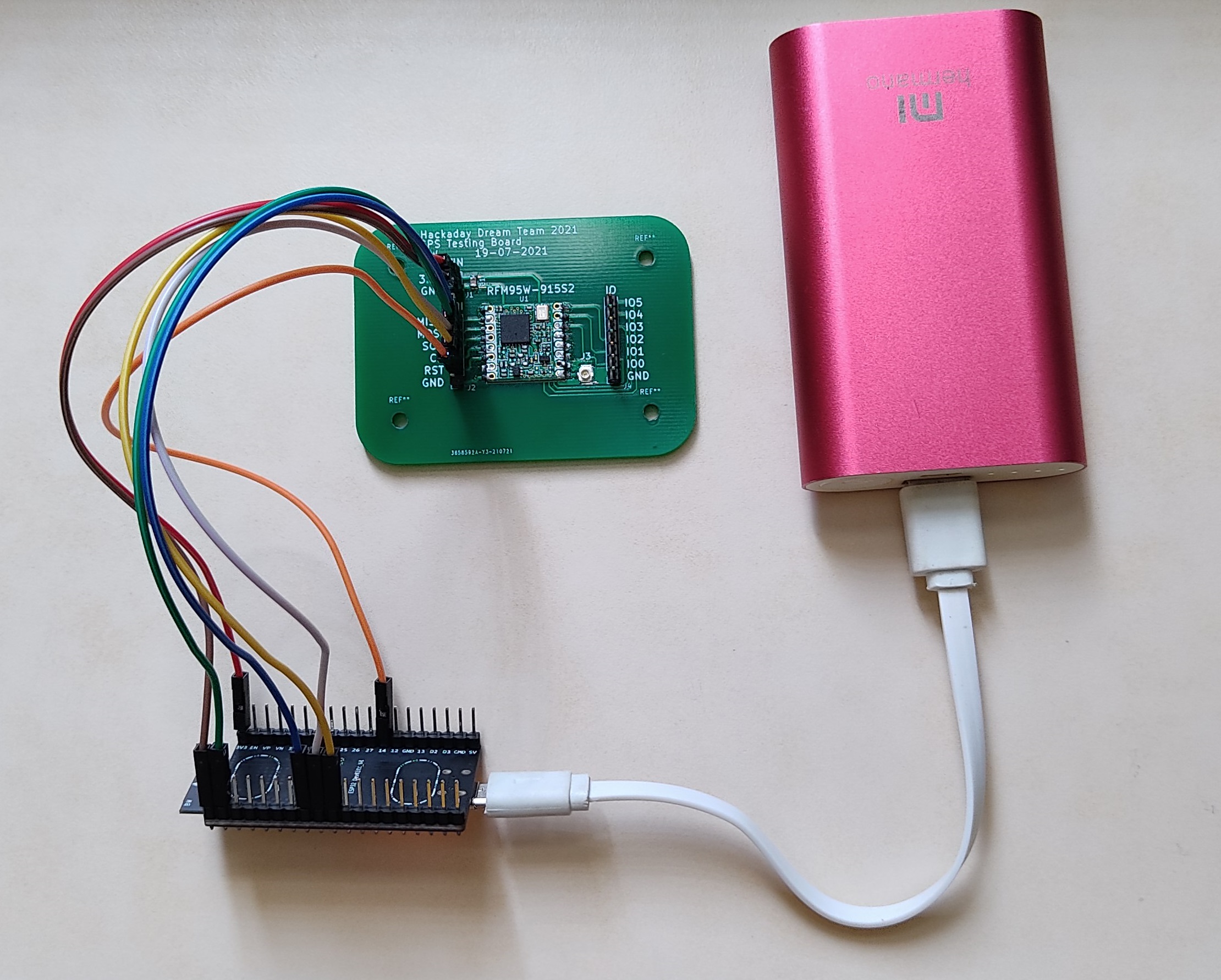
The webpage randomnerdtutorials.com has an amazing tutorial named ESP32 with LoRa using Arduino IDE – Getting Started, that tutorial contains detailed information about how to use the RFM95 with an ESP32 (the same microcontroller that was selected for our designs). I used the same firmware and connections provided by the tutorial.
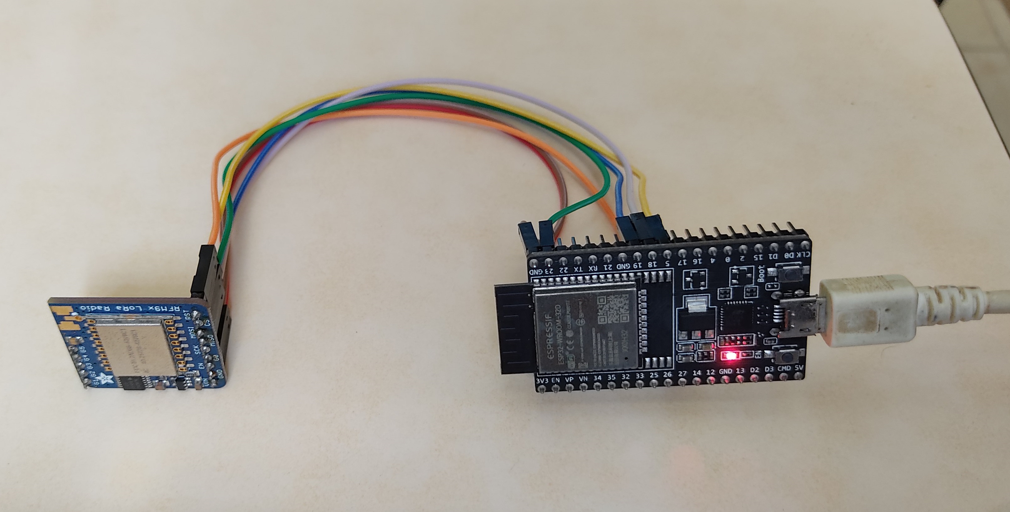
The test requires 2 transceivers, one of them will be used as a sender and the other as a receiver. In this case, one of the transceivers is the RFM95W-915S2 Development board and the other one is the RFM95W transceiver from Adafruit.
The connections are the following:
| ESP32 | RFM95W-915S2 Development Board |
|---|---|
| 3V3 | 3.3V |
| GND | GND |
| GPIO 14 | RST |
| GPIO 5 | CS |
| GPIO 18 | SCK |
| GPIO 23 | MOSI |
| GPIO 19 | MISO |
| ESP32 | RFM95W Board from Adafruit |
|---|---|
| 3V3 | VIN |
| GND | GND |
| GPIO 14 | RST |
| GPIO 5 | CS |
| GPIO 18 | SCK |
| GPIO 23 | MOSI |
| GPIO 19 | MISO |
This repository contains a folder named /Firmware/ that contains the project for the transceiver as a receiver and a sender.
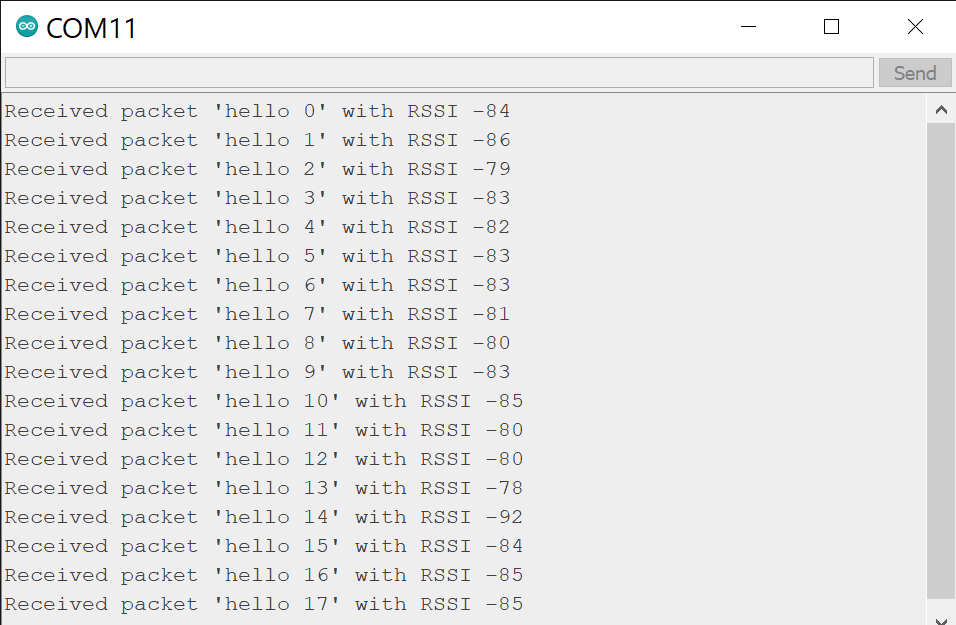
Both of the RFM95W Boards were used as a sender and receiver, the result was successful in both cases. During the test, one of the transceivers sends the package "hello counter", where the counter is a number that goes from 0 to 32767. The other transceiver receives the package and prints the message through serial.
Before you flash:
LoRa.begin(915E6) to match the RFM95W‑915S2 (915 MHz)
module fitted to this board. If you pair it with a module for another band, change
that argument (433E6 Asia, 866E6 Europe).LoRa.setSyncWord(0xF3)) or
they will ignore each other.NSS/CS → GPIO5, RST → GPIO14,
DIO0 → GPIO2, and hardware SPI (SCK GPIO18, MOSI GPIO23, MISO GPIO19).Results visualized in the serial monitor from the receiver circuit:
For more information about the firmware visit the original tutorial for the RFM95W.
README.md
LICENSE                              Apache 2.0
Schematic v1.0.pdf                   exported schematic
Images/                              schematic, 3D renders, board/antenna photos, test result
Firmware/
  esp32_RFM95_sender/                Arduino sketch, sender
  esp32_RFM95_receiver/              Arduino sketch, receiver
lora-testing-board/                  KiCad project
  lora-testing-board.pro/.sch/.kicad_pcb
  lora-testing-board.csv             BOM
  Symbols/ Footprints/ 3D/           project-local libraries
  Gerber/                            fabrication output
Exports/ STEP model| Qty | Value | Footprint | References |
|---|---|---|---|
| 1 | C-10uF-0805 | Capacitor_SMD:C_0805_2012Metric | C1 |
| 1 | Conn_01x02_Male | Connector_PinSocket_2.54mm:PinSocket_1x02_P2.54mm_Vertical | J1 |
| 1 | Conn_01x06_Male | Connector_PinSocket_2.54mm:PinSocket_1x06_P2.54mm_Vertical | J2 |
| 1 | Conn_01x07_Male | Connector_PinSocket_2.54mm:PinSocket_1x07_P2.54mm_Vertical | J4 |
| 1 | RFM95W-915S2 | RF_Module:HOPERF_RFM9XW_SMD | U1 |
| 1 | U.FL-R-SMT-1_10_ | U.FL-R-SMT-1(10):U.FL-R-SMT-1_10_ | J3 |
The 6 most common of 10 parts.
It measures 69 × 50 mm and has 2 copper layers, 1.6 mm thick.
10 parts, built around the RFM95W-915S2. The full list of its parts is on this page, with links to each part's symbol and footprint where PCBKit's library has them.
From the leonardoward/lora-development-boards repository on GitHub, at the commit this page was made from: the board is lora-testing-board/lora-testing-board.kicad_pcb. PCBKit opens the board in the browser, with nothing to install.
Its repository publishes it under the Apache-2.0 licence: you may reuse it on that licence's terms (keep the author's notice, and for a copyleft licence share your changes alike).

risejohan/2Bit
In this repo we can see some designs with free use for the community, 2 Bit electronic


nasheed-x/aether
Aether is a versatile flight computer for testing flight hardware and software, focusing on sensor fusion to monitor rocket states and interface with on-board systems.

usfsoar/irec-avionics-payload-pcb
KiCad project for the PCB in the payload of SOAR's IREC Rocket

RetiaLLC/DefconBadge2026
Retia 2024 DEF CON badge (ESP32-S3): docs, pinouts, flashable firmware incl. DOOM and Meshtastic, examples, KiCad hardware sources

ElectronicCats/CatWAN_Farmer
CatWAN Farmer, a grower's water saving open source project with LoRa

brev-dev/another_esp8266_sensor_board
PCB layout and instructions for a multi-purpose esp8266 sensor device, with optional LORA connectivity.