
2 layers215.2 × 163.6 mm
 lenaschimmel/bestelampe18
Die beste Lampe
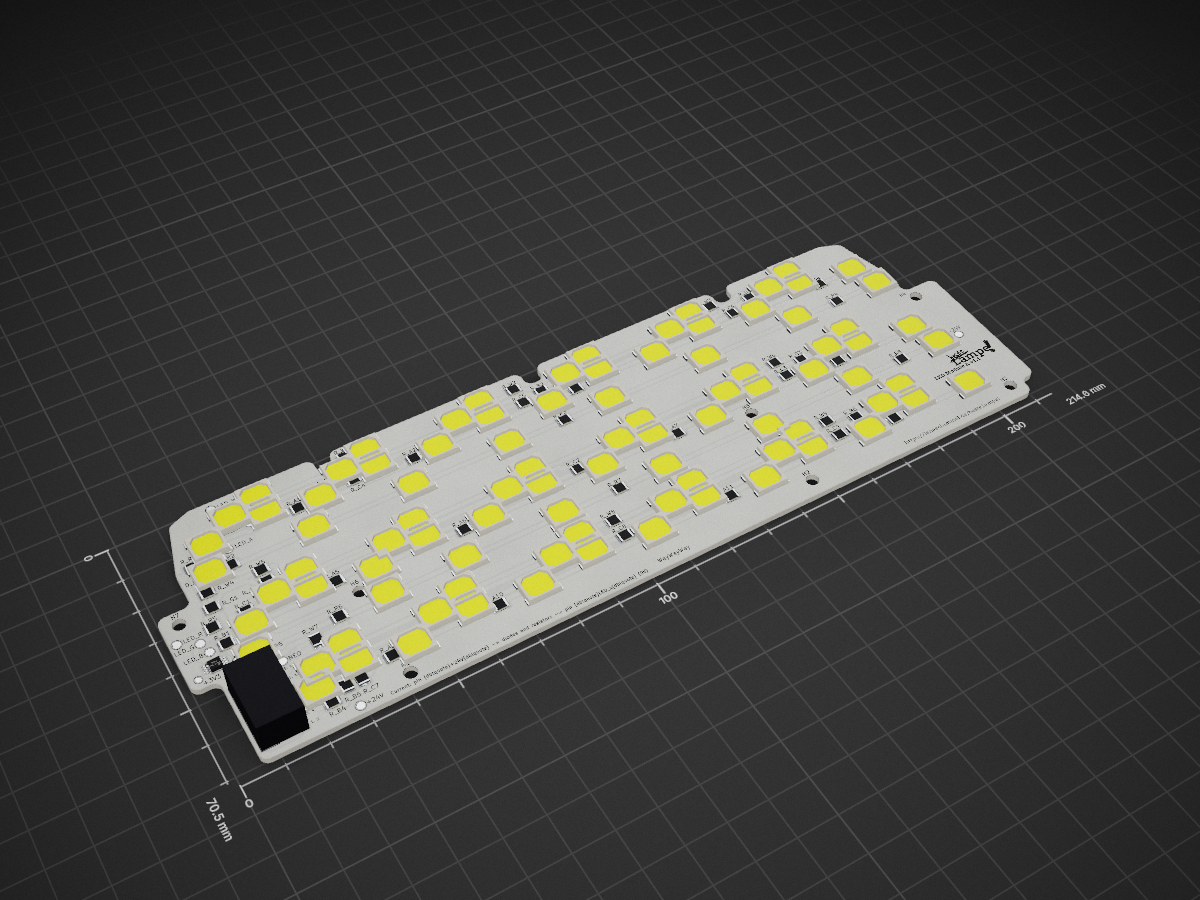
LED Module A is an open-source printed circuit board by lenaschimmel, from the lenaschimmel/bestelampe repository on GitHub. It is a 2-layer board of 214.6 × 70.5 mm with 160 parts on 143 nets, routed with 684 tracks and 0 vias.
It is built around the DS18B20U+. Its parts include 1 IC and 1 connector. It belongs with the lEDs and displays boards and the ESP32 boards of this library.
This module is flawed in countless ways, and I really recommend to not use it in any way. Not as it is, not as a basis for modification.
I just uploaded it for transparency, because I talk a lot about it on the Progress page. You can read about it's problems there.
This board should make it possible to have up to 10 high power LEDs with different colors aranged in a slim (2mm) and short (20mm) line. A TLC59711 is used to generate the 10 PWM signals, but it is not driving the LEDs directly. Instead, a line driver, MOSFETs and series resistors are used to power the LEDs without the complexities of a constant current drive.
| Qty | Value | Footprint | References |
|---|---|---|---|
| 30 | 18 Ohm, 0.5W, 1%, 1210 package | Resistor_SMD:R_1210_3225Metric | R_A2, R_A3, R_A4, R_A6, R_A7, R_A8, R_A10, R_A11, R_A12, R_C1, R_C2, R_C3, R_C4, R_C5, R_C6, R_C7 +14 |
| 21 | Amber | LED_SMD:LED_2835_CREE_JSE28L3E5_Big_Anode | D_A1, D_A2, D_A3, D_A4, D_A10, D_A11, D_A12, D_A13, D_A14, D_A15, D_A16, D_A17, D_A18, D_A19, D_A20, D_A21 +5 |
| 18 | Cold White | LED_SMD:LED_2835_CREE_JSE28L3E5 | D_C1, D_C2, D_C3, D_C4, D_C5, D_C6, D_C7, D_C10, D_C11, D_C12, D_C13, D_C14, D_C15, D_C18, DC_16, DC_17 +2 |
| 18 | Warm White | LED_SMD:LED_2835_CREE_JSE28L3E5 | D_W1, D_W2, D_W3, D_W4, D_W5, D_W6, D_W7, D_W10, D_W11, D_W12, D_W13, D_W14, D_W15, D_W16, D_W17, D_W18 +2 |
| 12 | 15 Ohm, 0.5W, 1%, 1210 package | Resistor_SMD:R_1210_3225Metric | R_B1, R_B2, R_B3, R_B4, R_B5, R_B6, R_R2, R_R3, R_R4, R_R6, R_R7, R_R8 |
| 12 | Royal Blue | LED_SMD:LED_2835_CREE_JSE28L3E5 | D_B1, D_B2, D_B3, D_B4, D_B5, D_B6, D_B7, D_B8, D_B9, D_B10, D_B11, D_B12 |
| 9 | TestPoint_Pad_D2.0mm | TestPoint:TestPoint_Pad_D2.0mm | +24V, +24V, LED_A, LED_B, LED_CW, LED_G, LED_R, LED_WW, NEO |
| 8 | Photo Red | LED_SMD:LED_2835_CREE_JSE28L3E5_Big_Anode | D_P1, D_P2, D_P3, D_P4, D_P5, D_P6, D_P7, D_P8 |
| 8 | Red | LED_SMD:LED_2835_CREE_JSE28L3E5_Big_Anode | D_R1, D_R2, D_R3, D_R4, D_R5, D_R6, D_R7, D_R8 |
| 7 | MountingHole | MountingHole:MountingHole_3.2mm_M3 | H1, H2, H3, H4, H5, H6, H7 |
| 6 | Green | LED_SMD:LED_2835_CREE_JSE28L3E5 | D_G1, D_G2, D_G3, D_G4, D_G5, D_G6 |
| 3 | 2.2 Ohm, 0.33W, 5%, 1210 package | Resistor_SMD:R_1210_3225Metric | R_A1, R_A5, R_A9 |
| 3 | TestPoint_Pad_D1.5mm | TestPoint:TestPoint_Pad_D1.5mm | +3V3, GND, TMP |
| 2 | 4.7 Ohm, 0.33W, 5%, 1210 package | Resistor_SMD:R_1210_3225Metric | R_R1, R_R5 |
| 1 | LOGO | ||
| 1 | Connector Header Surface Mount, Right Angle 14 position 0.100 (2.54mm) | Pin Header Wuerth:610114249121 | J1 |
| 1 | DS18B20U+ | Package_SO:MSOP-8_3x3mm_P0.65mm | U1 |


PaoloJN/sensei-puck
Drop-in BLE water sensor puck. College proof of concept, archived before the first board order.


ADolbyB/flipper-zero-files
A Collection Of Files From Various Sources Specifically For The Flipper Zero Device (In Progress)

zynthian/zynthian-hw
Zynthian hardware stuff: PCBs, schemes, parts specifications, pin assignment, ...

zli117/Pico-Keyboard
Hardware design for a mechanical keyboard based on RP2040


HaoboGu/rmk-ble-keyboard
A fully open source BLE/USB dual-mode GH60 keyboard powered by rmk

It measures 214.6 × 70.5 mm and has 2 copper layers, 1.6 mm thick.
160 parts, built around the DS18B20U+. The full list of its parts is on this page, with links to each part's symbol and footprint where PCBKit's library has them.
From the lenaschimmel/bestelampe repository on GitHub, at the commit this page was made from: the board is hardware/ledmodule/LED_Module_A/LED_Module_A.kicad_pcb. PCBKit opens the board in the browser, with nothing to install.
Its repository states no licence, so its author keeps all rights: ask lenaschimmel before reusing the design.