Skip to the content
PCBKitNew board
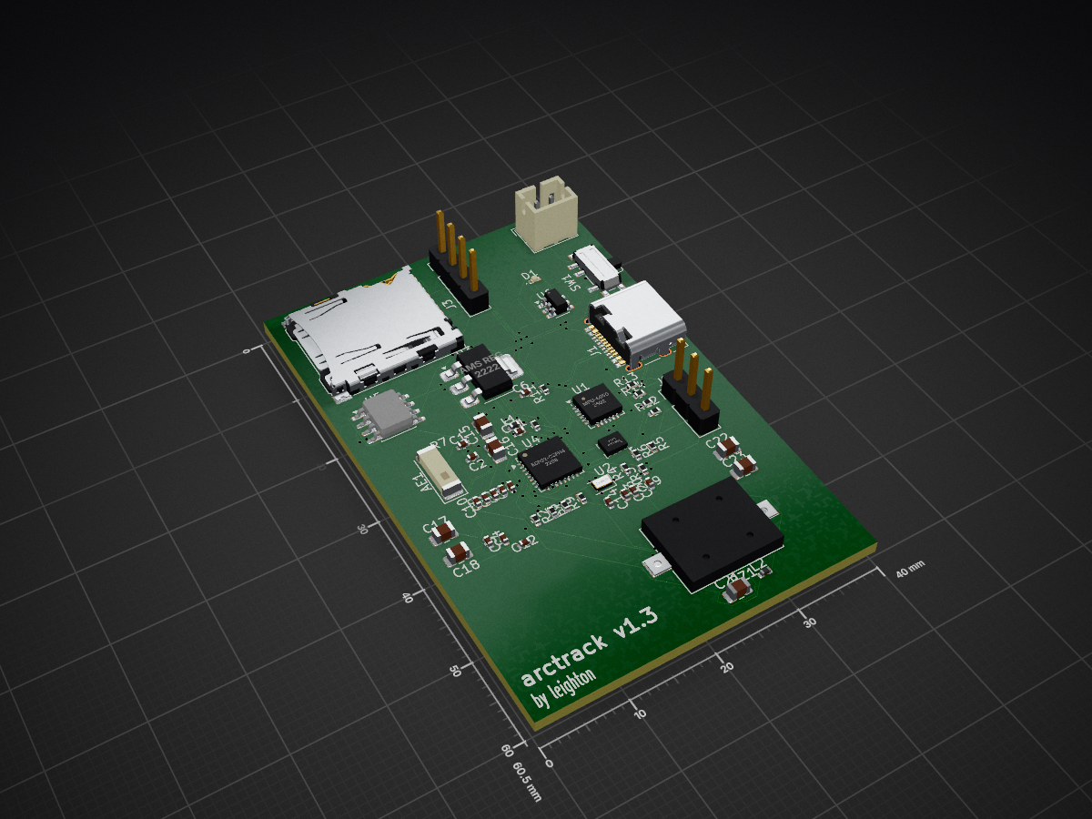
4 layers40 × 60.5 mmArctrack, the printed circuit board in 3D

a model rocket flight computer

Size
40 × 60.5 mm
Copper layers
4
Thickness
1.6 mm
Parts
55
Nets
60
Pads
239
Tracks, vias
1,075, 121
Pours
4
Routed
Yes
KiCad
KiCad 9.0 (file 20241229)
Created
10 Jul 2026
Updated
10 Jul 2026

Overview

Arctrack is an open-source printed circuit board by leeeeeeeeeeeeee2, from the leeeeeeeeeeeeee2/arctrack repository on GitHub, published under the GPL-3.0 licence. It is a 4-layer board of 40 × 60.5 mm with 55 parts on 60 nets, routed with 1,075 tracks and 121 vias.

It is built around the ESP32-C3FH4, BMP280 and MPU-6050, with the TP4056-42-ESOP8 among its other parts. Its parts include 23 capacitors, 14 resistors, 6 ICs, 5 connectors and 2 inductors. It belongs with the ESP32 and RISC-V boards of this library.

Main components

4

README

README.md

ArcTrack — Model Rocket Flight Computer

ArcTrack is a compact flight computer for model rockets. It logs altitude and motion to a microSD card, reads GPS, and lets you live-track the rocket over WiFi from your phone. v1.3 adds a power LED, buzzer, and servo header for nose-cone parachute deploy at apogee.

Designed for a BT-70 body tube with a 3D-printed nose avionics bay.

Hardware: bare ESP32-C3FH4 (QFN-32, 4MB flash) + 2.4 GHz chip antenna, USB-C, LiPo charger, 3.3 V regulator, BMP280, MPU-6050, microSD, GPS header, servo + 5 V boost.

RF note: chip-antenna matching may need tuning. See hardware/DESIGN.md.

Features

  • Altitude — BMP280 barometer + apogee detection
  • Motion — MPU-6050 IMU (launch / burnout)
  • GPS — ATGM336H (UART)
  • Logging — microSD CSV
  • Live tracking — WiFi AP + phone web dashboard
  • USB-C — charge + program (native USB)
  • 1S LiPo — TP4056 charging
  • Power LED — on whenever the board is powered
  • Buzzer — beeps (apogee / status)
  • Servo — parachute / nose deploy at apogee (5 V boost on board)

Repo layout

PathWhat
hardware/DESIGN.mdElectrical design, pinout, power, layout
hardware/BOM.mdBill of materials
hardware/WIRING.mdPin-by-pin wiring
hardware/kicad/PCB project (schematic + board)
hardware/gerbers/Fabrication outputs (when exported)
firmware/PlatformIO firmware for ESP32-C3

PCB / order

  1. Read hardware/DESIGN.md and hardware/WIRING.md
  2. Open the project in hardware/kicad/
  3. Order boards from JLCPCB (4-layer, ~70×40 mm). Use Gerbers from hardware/gerbers/ when present.
  4. Hand-solder: GPS module, battery connector, switch, servo header as needed

Firmware

bash
cd firmware
pio run                 # build
pio run -t upload       # flash over USB-C
pio device monitor      # serial logs

Phone: join WiFi ArcTrack / password launch123, open http://192.168.4.1

Pin map (firmware)

FunctionGPIO
I2C SDA / SCL4 / 5
SD SCK / MOSI / MISO / CS6 / 7 / 3 / 10
GPS RX / TX20 / 21
Buzzer0
Servo PWM1
Power LEDhardwired to 3.3 V (not a GPIO)

Author

Leighton — UK maker / rocketry + electronics builds.

Parts

55
QtyValueFootprintReferences
8100nCapacitor_SMD:C_0402_1005MetricC1, C2, C4, C5, C7, C8, C9, C10
610kResistor_SMD:R_0402_1005MetricR1, R2, R3, R4, R10, R11
310uCapacitor_SMD:C_0805_2012MetricC16, C17, C18
210pCapacitor_SMD:C_0402_1005MetricC13, C14
210uFCapacitor_SMD:C_0805_2012MetricC21, C22
21pCapacitor_SMD:C_0402_1005MetricC19, C20
21uCapacitor_SMD:C_0402_1005MetricC11, C12
24.7kResistor_SMD:R_0402_1005MetricR8, R9
25.1kResistor_SMD:R_0402_1005MetricR5, R6
1100kResistor_SMD:R_0402_1005MetricR14
1100uFCapacitor_SMD:C_0805_2012MetricC23
110nCapacitor_SMD:C_0402_1005MetricC3
112kResistor_SMD:R_0402_1005MetricR7
12.2nCapacitor_SMD:C_0402_1005MetricC6
12.2uHInductor_SMD:L_0402_1005MetricL2
12.7nHInductor_SMD:L_0402_1005MetricL1
122uCapacitor_SMD:C_0805_2012MetricC15
1330ΩResistor_SMD:R_0402_1005MetricR12
140MHzCrystal:Crystal_SMD_2012-2Pin_2.0x1.2mmY1
1510kResistor_SMD:R_0402_1005MetricR13
1AMS REGPackage_TO_SOT_SMD:SOT-223-3_TabPin2U3
1AntennaRF_Antenna:Johanson_2450AT43F0100AE1
1BMP280Package_LGA:Bosch_LGA-8_2x2.5mm_P0.65mm_ClockwisePinNumberingU2
1BuzzerBuzzer_Beeper:Buzzer_Mallory_AST1109MLTRQBZ1
1ESP32-C3FH4Package_DFN_QFN:QFN-32-1EP_5x5mm_P0.5mm_EP3.7x3.7mmU4
1GPS HEADERSConnector_PinHeader_2.54mm:PinHeader_1x04_P2.54mm_VerticalJ4
1JST BATTERY CONNECTORConnector_JST:JST_PH_B2B-PH-K_1x02_P2.00mm_VerticalJ2
1LEDLED_SMD:LED_0402_1005MetricD1
1MPU-6050Sensor_Motion:InvenSense_QFN-24_4x4mm_P0.5mmU1
1Micro_SD_CardConnector_Card:microSD_HC_Hirose_DM3AT-SF-PEJM5J3
1POWER SWITCHButton_Switch_SMD:SW_SPDT_PCM12SW1
1SERVOConnector_PinHeader_2.54mm:PinHeader_1x03_P2.54mm_VerticalJ5
1SERVO 5V BOOSTPackage_TO_SOT_SMD:SOT-23-6U6
1TP4056-42-ESOP8Package_SO:SOIC-8-1EP_3.9x4.9mm_P1.27mm_EP2.41x3.3mm_ThermalViasU5
1USBC CHARGE PORTConnector_USB:USB_C_Receptacle_HRO_TYPE-C-31-M-12J1

Questions

How big is the Arctrack PCB?

It measures 40 × 60.5 mm and has 4 copper layers, 1.6 mm thick.

What parts does the Arctrack use?

55 parts, built around the ESP32-C3FH4, BMP280, MPU-6050 and TP4056-42-ESOP8. The full list of its parts is on this page, with links to each part's symbol and footprint where PCBKit's library has them.

Where can I download the Arctrack KiCad files?

From the leeeeeeeeeeeeee2/arctrack repository on GitHub, at the commit this page was made from: the board is hardware/kicad/arctrack.kicad_pcb and its schematic hardware/kicad/arctrack.kicad_sch. PCBKit opens the board in the browser, with nothing to install.

Can I use the Arctrack design in my own project?

Its repository publishes it under the GPL-3.0 licence: you may reuse it on that licence's terms (keep the author's notice, and for a copyleft licence share your changes alike).

Similar boards

  • 4 layers26 × 19.1 mmCanSat, the printed circuit board in 3D

    CanSat

    TanujRai14/Sat_pcb_design

    This repository contains the PCB design files and documentation for a Can Satellite, featuring multiple environmental and orientation sensors, power management, and wireless communication capabilities.
    35 partsCERN-OHL-S-2.0
  • 2 layers85.1 × 65.4 mmTx module, the printed circuit board in 3D

    Tx module

    koushik12328/Smart_mining_helmet

    An ESP32-powered safety helmet featuring gas detection, impact sensing, and IoT connectivity

    27 partsMIT
  • 2 layers115 × 115 mmDrone, the printed circuit board in 3D

    Drone

    rmingon/drone-uwb

    Drone design for automatic position in space with UWB

    49 parts13
  • 4 layers45 × 89 mmFlight controller v2, the printed circuit board in 3D

    Flight controller v2

    Eryk-Mozdzen/uav-tvc-goose

    Single rotor, thrust vector controlled UAV

    115 parts9
  • 2 layers50 × 63 mmZenith Development Board, the printed circuit board in 3D

    Zenith Development Board

    zenitheesc/Zenith-Development-Board

    The Zenith Development Board was developed to serve as a first project for the new members of the group.

    69 parts3MIT
  • 2 layers96.6 × 100 mmQuadRaptor, the printed circuit board in 3D

    QuadRaptor

    abdosalem490/QuadRaptor

    148 parts2MIT
  • 4 layers62.2 × 54.6 mmFlight ControllerV1.0, the printed circuit board in 3D

    Flight ControllerV1.0

    alihaanc/SKYKILLER-Development-Board

    Drone and Rocket Development PCB board

    59 parts2
  • 2 layers38 × 38 mmMetalBird v2.kicad pro, the printed circuit board in 3D

    MetalBird v2.kicad pro

    Rajveer1496/MetalBird

    A Drone made entirely from scratch. From PCB design and body to own Firmware.

    67 parts2