
2 layers30.5 × 63 mm
Adbuino
akuker/adbuino
Arduino-based USB keyboard and Mouse to ADB adapter. Allows USB keyboards and mice to be used with vintage Macintosh computers.
75 parts60

ATmega-based RFID Door Lock
Ver3 is an open-source printed circuit board by leecurrent04, from the leecurrent04/Epic_DoorLock repository on GitHub, published under the GPL-3.0 licence. It is a 2-layer board of 60 × 70 mm with 40 parts on 36 nets, routed with 414 tracks and 27 vias.
It is built around the ATMEGA328P-AU and AMS1117-3.3. Its parts include 11 resistors, 5 capacitors, 4 diodes, 4 switches and 3 ICs. It belongs with the radio and wireless boards and the AVR (ATmega, ATtiny) boards of this library.


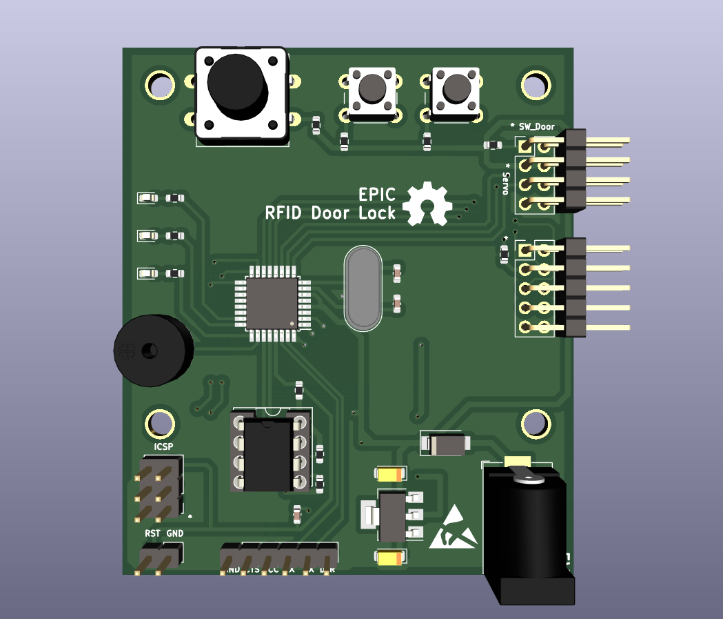
연초고등학교 EPIC 동아리(2021~2022) 에서 교내 학생들의 자발적인 탐구 활동을 장려하기 위해 진행한 프로젝트 입니다.
하드웨어 설계는 KiCAD 를 사용하였고, 소프트웨어는 avr-gcc 컴파일러를 이용한 avr C 언어로 작성되었습니다.
Makefile을 이용하여 컴파일하는 경우, Makefile과 같은 위치에 out 폴더를 생성해야 합니다.
| 필요한 패키지 | 설명 |
|---|---|
| avr-gcc | 컴파일러 |
| avr-libc | 라이브러리 |
| avr-size | 메모리 사용량 확인 |
| avrdude | 업로더 |
Set up (Debian)
패키지 설치는 Debian 기준으로 설명하고 있습니다. 자신의 환경에 맞추어 사용하시길 바랍니다.
apt update && apt upgrade
apt install avr-gcc avr-libc avr-size avrdude
Download source code
git clone https://github.com/leecurrent04/Epic_DoorLock
cd ./Epic_DoorLock/ver3/code/avr/
Set admin card
main.c 파일의 16, 17줄을 편집하여 관리자 카드를 등록합니다.
RFID 카드의 4byte UID 코드를 1byte씩 기입합니다. 카드의 UID 코드는 [NFC Tools - Google Play] 프로그램을 통하여 알 수 있습니다. (프로그램내 시리얼 번호 확인)
반드시 등록한 관리자 카드의 갯수에 맞게 cardAdmin_Num 값을 변경해주어야 합니다.
#define cardAdmin_Num 2
uint8_t cardAdmin_UID[cardAdmin_Num][4] = {
        {0x12, 0x34, 0x56, 0x78},
        {0x0A, 0x0B, 0x0C, 0x0D}
};
Complile
변경 사항을 저장한 후 아래 명령어를 이용하여 코드를 컴파일 합니다.
mkdir out
make all
또는 다음과 같은 명령어를 사용할 수 있습니다.
avr-gcc -Wall -mmcu=atmega168p -Os main.c ./lib/* -o ./out/output.o
avr-objcopy -j .text -j .data -O ihex ./out/output.o ./out/main.hex
Upload
Makefile 의 2, 4, 5번째 줄을 환경에 맞게 편집합니다.
PORT=/dev/ttyUSB0       # SET YOUR PORT
OBJ_FILES=./lib/*
BaudRate=115200         # SET BuadRate
PROGRAMMER=arduino      # SET Programmer
아래의 명령어를 터미널에 입력하여 업로드 합니다.
make flash
USBtinyISP를 사용하는 경우(권장), 다음의 명령어를 터미널에 입력하면 됩니다.
avrdude -v -p m168p -c usbtiny -U flash:w:./out/main.hex:iMicrochip AVR GCC Compiler 를 사용하여 Linux와 같은 과정을 따르거나, ATMEL Studio를 사용하십시오.
자세한 과정은 『아트멜 스튜디오와 아두이노로 배우는 ATmega328 프로그래밍(허경용)』 도서를 참고하십시오.
(이 프로젝트는 ATmega168p을 사용하였으므로, 업로드 과정에서 유의)
RFID 관련 AVR 라이브러리 : https://github.com/asif-mahmud/MIFARE-RFID-with-AVR
| Qty | Value | Footprint | References |
|---|---|---|---|
| 6 | 10K | Resistor_SMD:R_0603_1608Metric | R1, R2, R3, R4, R5, R6 |
| 4 | HOLE1, HOLE2, HOLE3, HOLE4 | ||
| 3 | 220 | Resistor_SMD:R_0603_1608Metric | R7, R8, R9 |
| 3 | LED_Small | LED_SMD:LED_0603_1608Metric | D2, D3, D4 |
| 2 | 10uF | Capacitor_Tantalum_SMD:CP_EIA-3216-10_Kemet-I | C4, C5 |
| 2 | 22pF | Capacitor_SMD:C_0603_1608Metric | C2, C3 |
| 2 | 4.7K | Resistor_SMD:R_0603_1608Metric | R10, R11 |
| 2 | SW_Push | Button_Switch_THT:SW_PUSH_6mm_H5mm | SW3, SW4 |
| 1 | 0.1uF | Capacitor_SMD:C_0603_1608Metric | C1 |
| 1 | 16MHz | Crystal:Crystal_HC49-4H_Vertical | Y1 |
| 1 | 1N4004 | Diode_SMD:D_SMA | D1 |
| 1 | 5.5pi | Connector_BarrelJack:BarrelJack_Horizontal | POWER_JACK1 |
| 1 | AMS1117-3.3 | Package_TO_SOT_SMD:SOT-223-3_TabPin2 | U2 |
| 1 | AT24CS16 | Package_DIP:DIP-8_W7.62mm_Socket_LongPads | U3 |
| 1 | ATmega328P-A | Package_QFP:TQFP-32_7x7mm_P0.8mm | U1 |
| 1 | Buzzer | SW:FQ-014[Buzzer] | BZ1 |
| 1 | Conn_01x06_Female | Connector_PinHeader_2.54mm:PinHeader_1x06_P2.54mm_Vertical | J_UART1 |
| 1 | Conn_02x03_Odd_Even | Connector_PinHeader_2.54mm:PinHeader_2x03_P2.54mm_Vertical | J_SPI1 |
| 1 | Conn_02x04_Odd_Even | Connector_PinHeader_2.54mm:PinHeader_2x04_P2.54mm_Vertical | J_INNER1 |
| 1 | Conn_02x05_Odd_Even | Connector_PinHeader_2.54mm:PinHeader_2x05_P2.54mm_Vertical | J_OUTPUT1 |
| 1 | ESD-Logo_6.6x6mm_SilkScreen | Symbol:ESD-Logo_6.6x6mm_SilkScreen | REF_ESD |
| 1 | OSHW-Symbol_6.7x6mm_SilkScreen | Symbol:OSHW-Symbol_6.7x6mm_SilkScreen | REF_OSHW |
| 1 | SW_Push | Connector_PinHeader_2.54mm:PinHeader_1x02_P2.54mm_Vertical | SW1 |
| 1 | SW_Push | Button_Switch_THT:SW_PUSH-12mm | SW2 |
It measures 60 × 70 mm and has 2 copper layers, 1.6 mm thick.
40 parts, built around the ATMEGA328P-AU and AMS1117-3.3. The full list of its parts is on this page, with links to each part's symbol and footprint where PCBKit's library has them.
From the leecurrent04/Epic_DoorLock repository on GitHub, at the commit this page was made from: the board is ver3/pcb/pcb.kicad_pcb and its schematic ver3/pcb/pcb.kicad_sch. PCBKit opens the board in the browser, with nothing to install.
Its repository publishes it under the GPL-3.0 licence: you may reuse it on that licence's terms (keep the author's notice, and for a copyleft licence share your changes alike).
akuker/adbuino
Arduino-based USB keyboard and Mouse to ADB adapter. Allows USB keyboards and mice to be used with vintage Macintosh computers.

djtersteegc/smartportsd
Various PCB and case designs of the SmartPortSD hard disk emulator for Apple II computers.

kvazimoda24/TionO2-ZigBee
Ядром проекта является микроконтроллер ATmega328P. Для работы по протоколу ZigBee используется модуль E18-MS1-PCB.

sherrardTr4129/RealSense-BNO055-Pose-Estimation
This repository contains required software to construct a Pose of a vision target by fusing its x,y,z coordinates from the Intel RealSense depth camera, with its quaternion orientation from the BNO055 sensor.

djtersteegc/tapecart-sd-vertical
Vertical SMD PCB design and 3D printable case of the TapeCart SD for the Commodore 64


d-diot/Mini-BT-Pcb-328P
MySensors ATMega328P + RFM69 and NRF24 battery (AAA and CR2032) powered pcb

spacebiz24/Thermal-Profiling
A Thermal Profiling Platform built with ATMega328P and MAX31856