2 layers90 × 38 mm
LCD OLinuXino-5TS Rev.B
OLIMEX/OLINUXINO
OLINUXINO is Open Source / Open Hardware, low cost from EUR 24 Linux Industrial grade Single Board Computer capable to operate -25+85C
56 parts1.5k

 kzalesak/Schmittsynth3
A PCB of a basic 40106 Schmitt trigger based oscillator. Developed for an Engineers Without Borders workshop at University College London. Allows you to generate square waves based on turnable knobs and light input.
40106 synth is an open-source printed circuit board by kzalesak, from the kzalesak/Schmittsynth repository on GitHub. It is a 2-layer board of 99 × 99 mm with 56 parts on 32 nets, routed with 183 tracks and 3 vias.
Its parts include 29 connectors, 10 resistors, 7 capacitors, 4 diodes and 1 IC. It belongs with the audio and music boards of this library.
A simple square-wave synthesizer circuit using inverting gates (Logical NOT, Schmitt triggers) in the 40106 Integrated Circuit and a few discrete components. The KiCAD schematic, Printed Circuit Board (PCB) and a cached library are provided. This project was developed for the University College London branch of Engineers Without Borders as a basis for a workshop.
DEPRECATION NOTE
This project is deprecated - please use the upgraded version, Digisynth, available at https://github.com/kzalesak/Digisynth
In order to view and edit the files you are going to need the open source circuitry tool KiCAD, available from:
http://kicad-pcb.org/After installing KiCAD, the project should simply open upon clicking on the 40106_synth.pro file. From here, you can view the schematic and PCB Layout
The circuit works by connecting a Schmitt inverter (NOT Gate) in a feedback loop. The inverter outputs a HIGH voltage on its output pin when there is LOW voltage on its input pin and vice versa. By connecting a capacitor between the input pin and ground, we control how long it takes for a voltage change to propagate from the output pin to the input pin, effectively controlling our oscillation frequency. This is proportional to the capacity of our capacitor, as a larger capacitor will take longer to charge. We further connect the input and output pins via a variable resistor (potentiometer), thereby controlling how much current flows between the output pins and to the capacitor, limiting how fast it can charge. We thus obtain an oscillating circuit in which we can control the frequency by changing the capacitance and resistance of the respective components.
In order to operate your synth, you need to connect one of the inverting gates to (see under text for demo connections):
a capacitor on its input pin - you can do this by placing a capacitor between the female pin header below or above the 40106 IC (black box with legs in the middle of the board). Note that cylindrical capacitors with a stripe (electrolytic) are polarized, and the stripe should be connected to ground, as in the example setup. If your capacitor is soldered on, simply choose the desired gate.
a resistance between the input and output pin of the gate (not OUTPUT) - this allows you to control the tone, as well as ensures the sound is in the audible range and not ultrasound, which annoys animals. You can use a potentiometer or the photoresistor on the board, or use wires to connect to a resistive material, like a pencil drawing or a piece of fruit. You can also connect multiple resistors in series or parallel, to experiment with different effects.
appropriate sound OUTPUT pin to the voltage divider IN pin - use the same letter as the one next to the gate. To visualise what is happening, you can choose a large value capacitor (>100uF) and connect the OUTPUT pin to the LED instead. The voltage divider is required to bring down the voltage to standard audio levels (9V -> ~1.5V).
voltage divider DIV pin to left or right channel to use both, connect them together.
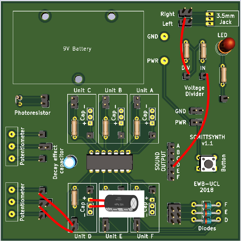
A sample setup using a potentiometer and gate D is shown here:
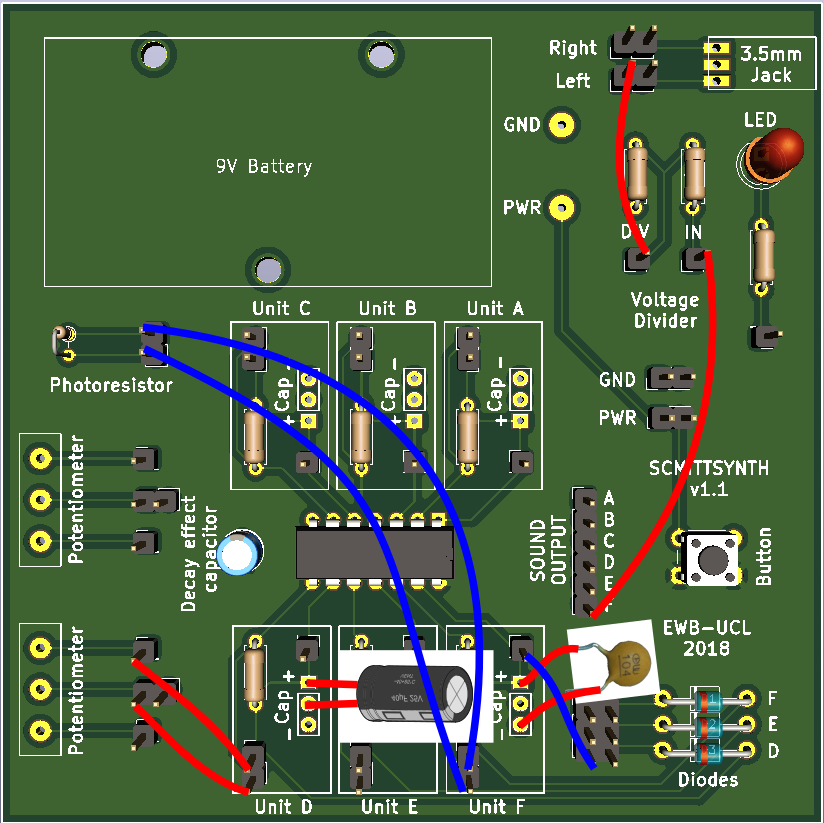
Oscillators can be set up in a "synced" mode by having one oscillator control the second one. This is achieved by connecting one oscillator output (or input) pin through a diode to the input pin of the other, periodically bringing the input pin of the second one high, thus turning its output low. The first one then controls the pitch of the tone and the second one controls timbre, or the color of the sound. It is necessary that the frequency of the first one is sufficiently lower then the second one, otherwise the second one will fail to trigger within the necessary time period and the circuit will stay silent. It is thus recommended to use a larger capacitor for the first oscilator and a smaller one for the second.
An example setup using gate D to control gate F is shown here:
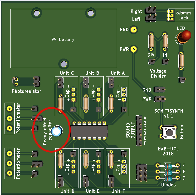
When the decay capacitor is added, an interesting envelope effect upon power off is created, a combination of decreasing volume and increasing frequency. It is recommended that a female pin header is soldered in place of the capacitor allowing a quick change of the capacitor. A large value (>10uF) is necessary for the effect to be strongly apparent. Pay attention to the polarity, the negative lead position is marked white.
This is the decay capacitor on the board:
DO NOT MAKE THIS PCB. IT IS HERE FOR ARCHIVAL PURPOSES. USE THE NEWER DIGISYNTH INSTEAD
This project is licensed under the TAPR Open Hardware License (www.tapr.org/OHL).
I would like to thank Engineers Without Borders for making it possible to run workshops where we built the and explored the circuit.
| Qty | Value | Footprint | References |
|---|---|---|---|
| 13 | Conn_01x01 | Connector_PinHeader_2.54mm:PinHeader_1x01_P2.54mm_Vertical | J1, J4, J7, J8, J11, J12, J19, J23, J24, J25, J26, J30, J31 |
| 13 | Conn_01x02 | Connector_PinHeader_2.54mm:PinHeader_1x02_P2.54mm_Vertical | J2, J3, J5, J9, J13, J14, J18, J21, J22, J27, J28, J29, J101 |
| 9 | R | Resistor_THT:R_Axial_DIN0207_L6.3mm_D2.5mm_P7.62mm_Horizontal | R1, R2, R3, R4, R5, R6, R7, R8, R9 |
| 6 | CP | AAA_Project Footprints:cap_2+3 | C1, C2, C3, C4, C5, C6 |
| 3 | D | AAA_Project Footprints:Diode_P10.16mm_Horizontal | D1, D2, D3 |
| 2 | POT | AAA_Project Footprints:SR_PASSIVES_POT_PW1.00_P5.00 | RV1, RV2 |
| 1 | 40106 | Package_DIP:DIP-14_W7.62mm | U1 |
| 1 | Audio-Jack-3 | AAA_Project Footprints:Jack_3.5mm_Boom_Precision_DC-003A | J32 |
| 1 | Battery_Cell | AAA_Project Footprints:BatteryHolder_COMF_BH9VA_1x6F22(9V) | BT1 |
| 1 | CP | Capacitor_THT:CP_Radial_D5.0mm_P2.50mm | C7 |
| 1 | Conn_01x06 | Connector_PinHeader_2.54mm:PinHeader_1x06_P2.54mm_Vertical | J100 |
| 1 | Conn_02x03_Counter_Clockwise | Connector_PinHeader_2.54mm:PinHeader_2x03_P2.54mm_Vertical | J16 |
| 1 | LED | LED_THT:LED_D5.0mm | D4 |
| 1 | R_PHOTO | Resistor_THT:R_Axial_DIN0204_L3.6mm_D1.6mm_P2.54mm_Vertical | R101 |
| 1 | SW_DIP_x02 | Button_Switch_THT:SW_PUSH_6mm | SW1 |
The 55 most common of 56 parts.
OLIMEX/OLINUXINO
OLINUXINO is Open Source / Open Hardware, low cost from EUR 24 Linux Industrial grade Single Board Computer capable to operate -25+85C

hackclub/OnBoard
💡 Join 1,000 teenagers and make your first PCB with a $100 grant!


GEIGEIGEIST/KLOTZ
KLOTZ is 34 keys column-staggered split keyboard. It uses an encoder and three status LEDs on each side.

ergonautkb/one
Ergonaut One is an open-source ergonomic wireless split mechanical keyboard designed by Ergonaut Keyboards.

matthewcieplak/super-sixteen
Code and schematics for the Super Sixteen Eurorack sequencer

EnriqueNeyra/Aeroq
An Indoor Air Quality Monitor Powered by ESP32, SCD40, and SEN54
It measures 99 × 99 mm and has 2 copper layers, 1.6 mm thick.
56 parts. The full list of its parts is on this page, with links to each part's symbol and footprint where PCBKit's library has them.
From the kzalesak/Schmittsynth repository on GitHub, at the commit this page was made from: the board is 40106_synth/40106_synth.kicad_pcb. PCBKit opens the board in the browser, with nothing to install.
Its repository states no licence, so its author keeps all rights: ask kzalesak before reusing the design.