
4 layers149.9 × 125.7 mm
Helios
kyriosaa/helios
A real-time controller that automatically turns on a lamp in my room every morning based on an alarm
91 parts

 kyriosaa/helios
A real-time controller that automatically turns on a lamp in my room every morning based on an alarm
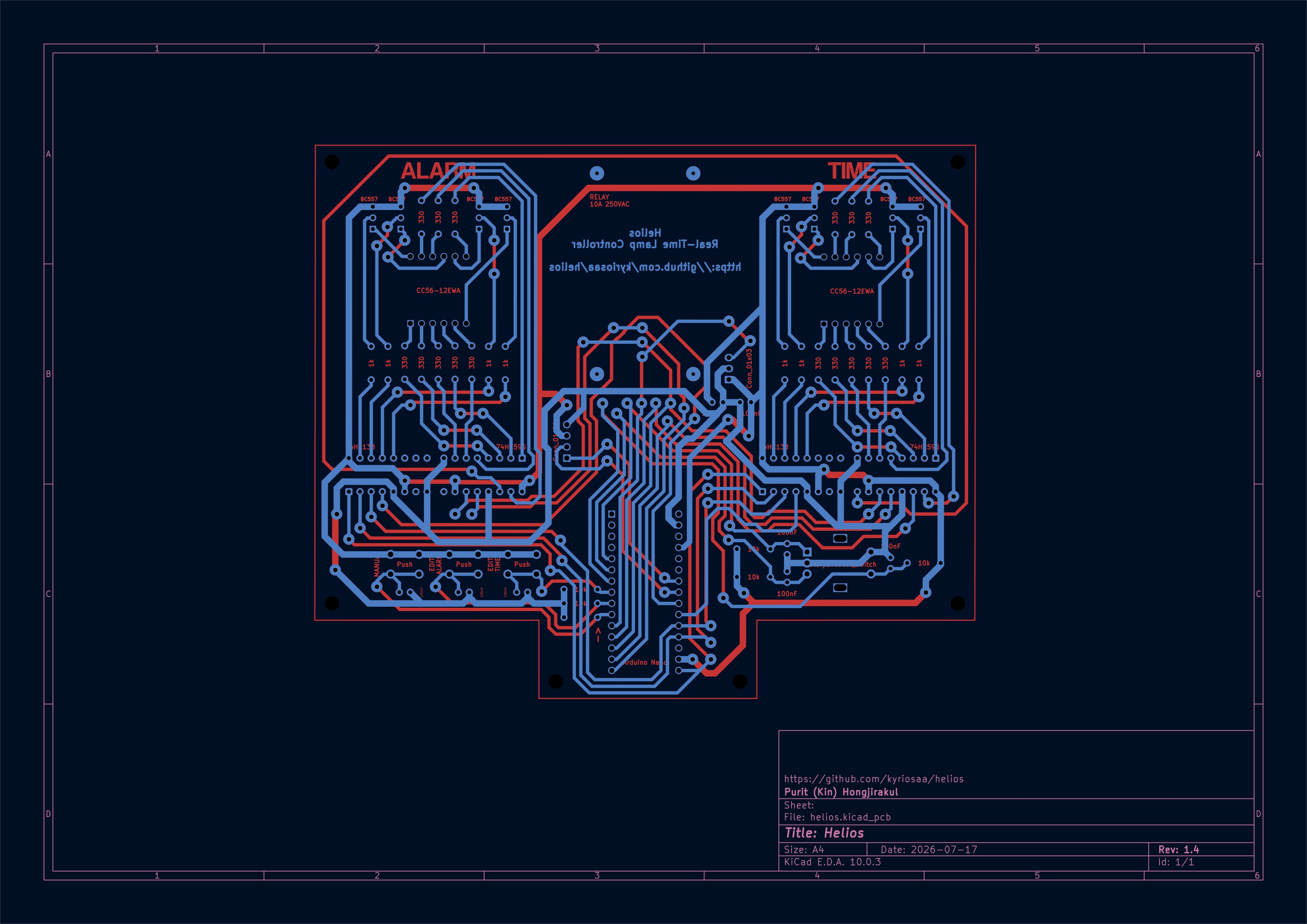
Helios is an open-source printed circuit board by kyriosaa, from the kyriosaa/helios repository on GitHub. It is a 2-layer board of 149.9 × 125.7 mm with 67 parts on 97 nets, routed with 817 tracks and 97 vias.
It is built around the 74HC138, 74HC595 and BC557. Its parts include 30 resistors, 8 capacitors, 8 transistors, 6 ICs and 4 switches. It belongs with the lEDs and displays boards and the AVR (ATmega, ATtiny) boards of this library.


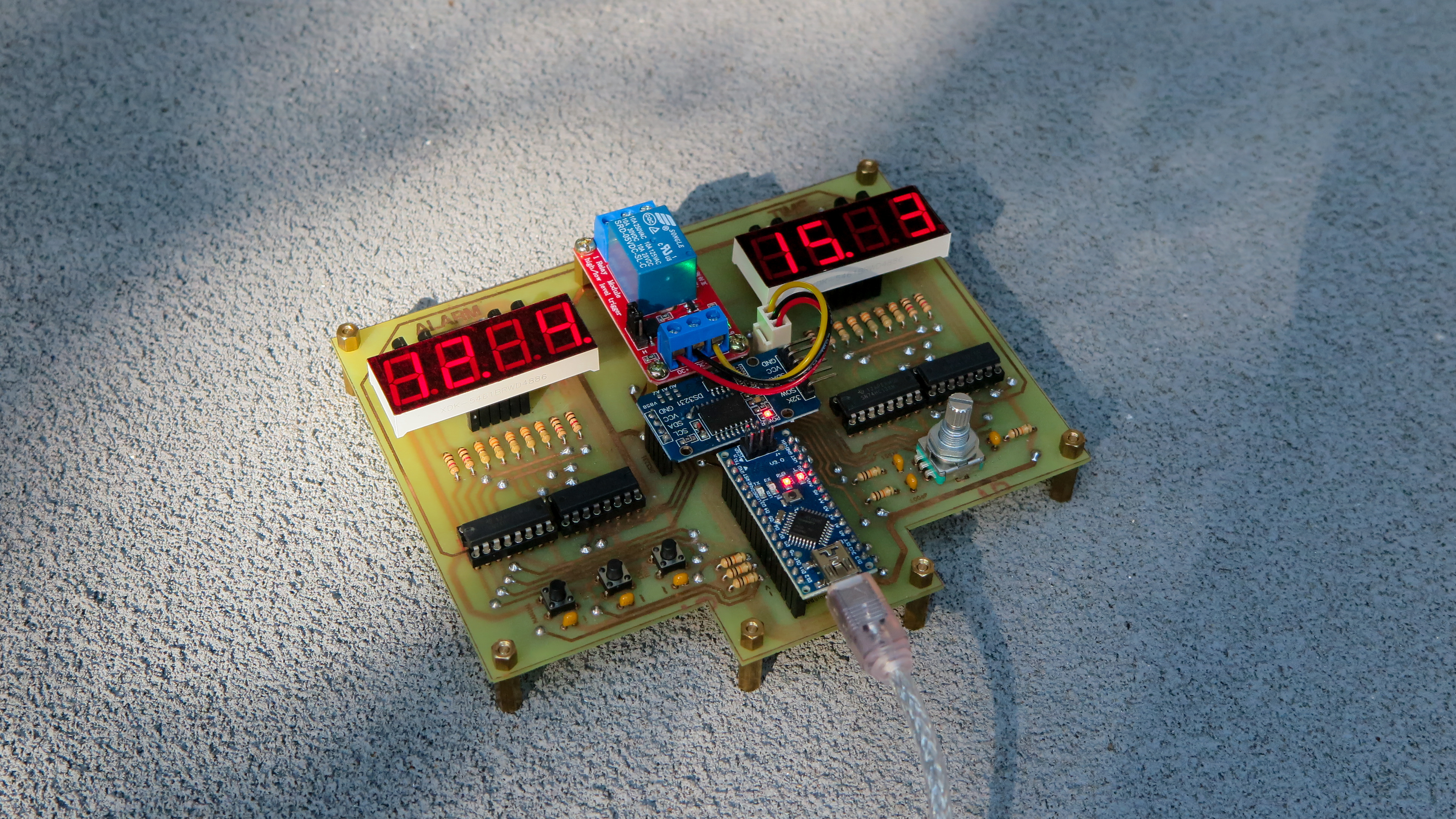


A real-time lamp controller for my room. Keeps the time (even when unplugged) and flips a relay once the clock and alarm values match.
My room doesn't have windows so I created this device to automatically turn on my bedside lamp and put myself into fight or flight every morning to help me wake up in time for work/school.
🎥 Demo Video 🎥
Some notes on why the board is built the way it is.
The RTC has its own coin-cell backup, so the clock survives a power outage or being moved to another room. Keeping time on the MCU would mean re-setting the clock every time the device lost power, which is exactly the kind of small annoyance that would make me stop using it.
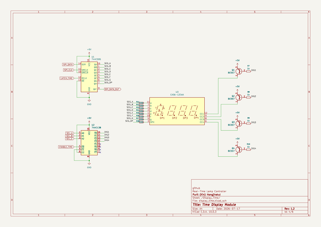
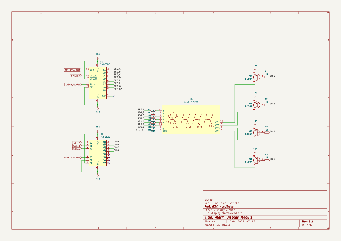
A MAX7219 or TM1637 would have done this with fewer parts and less code. I used two 74HC595s for the segments and a 74HC138 plus PNP high-side drivers per display because I to practice building the multiplexing myself instead of buying it in a chip.
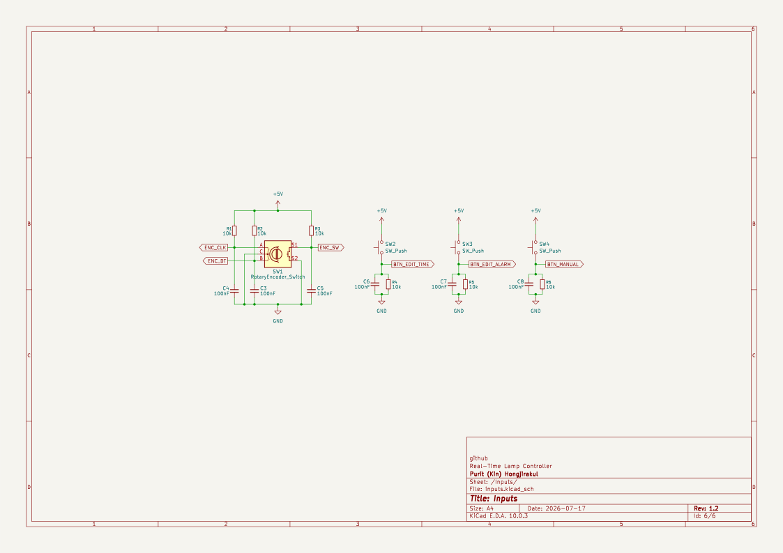
Every input has a 10k resistor and a 100nF capacitor on it to filter out switch bounce. The tradeoff to this is that signals now fade between HIGH and LOW over about a millisecond instead of snapping. During that fade, the Arduino can't really tell which one it's looking at, so a little noise makes it read HIGH-LOW-HIGH-LOW a few times before settling. An interrupt on ENC_CLK (D2) would count every one of those HIGH-LOW flips, so one click of the encoder knob would add 3 or 4 counts. However, reading the pin in the loop() function only ever sees the value after it settles, which solves the issue.
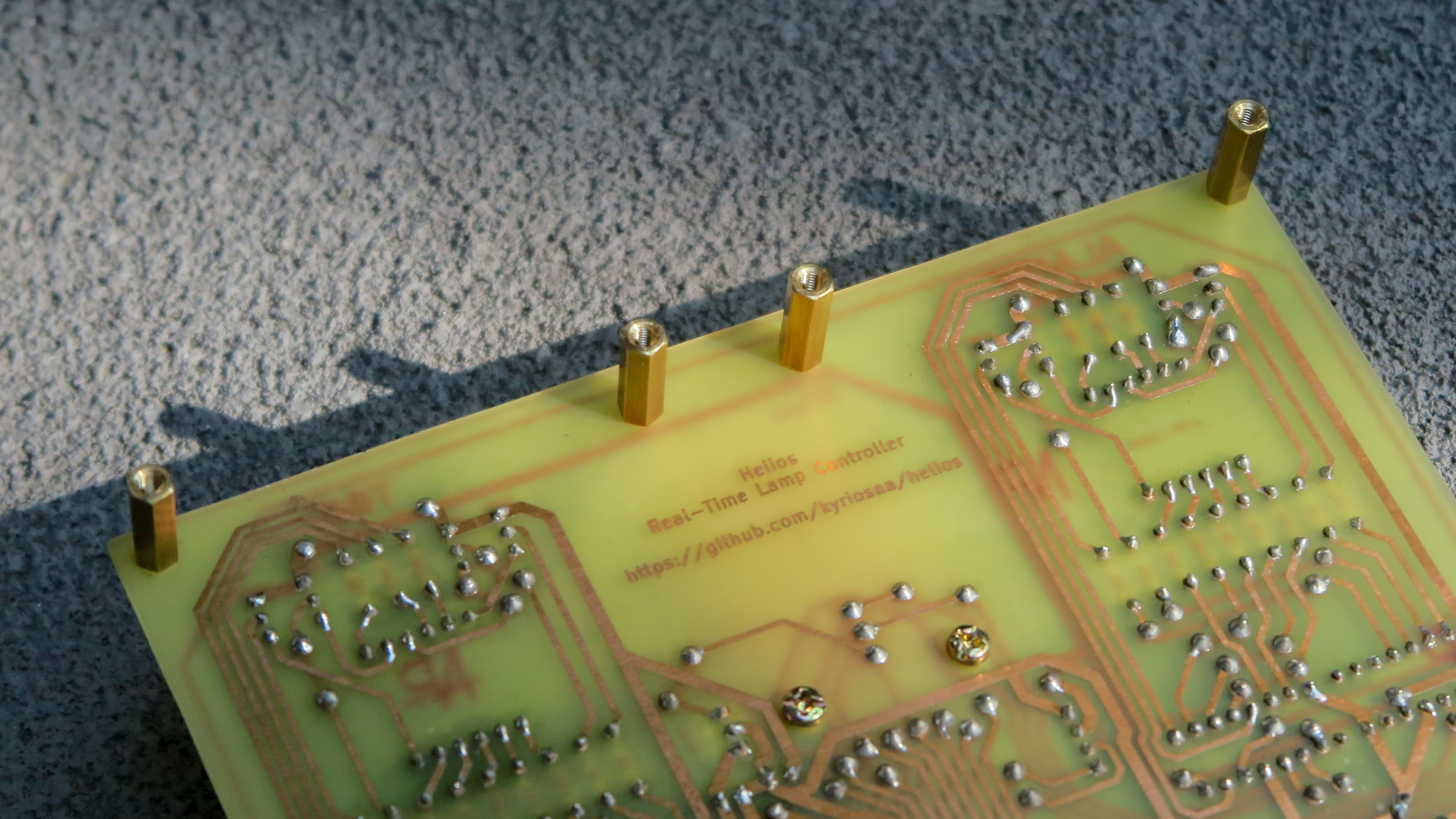
The 2-layer version is meant to be manually etched. But I know most people dont have an etching machine, so the 4-layer version is for anyone who doesn't have an etching setup and would rather send it to a manufacturer (I'm also experimenting with curved traces on the 4-layer version).
| Feature | Description |
|---|---|
| 24/7 Timekeeping | A coin battery supports the DS3231, so pulling the plug doesn't require a manual time recalibration |
| Dual Displays | Separate 7-segment displays for the current time and alarm |
| Manual Override | One button forces the lamp on and disarms the alarm. The armed state is shown by a decimal point on the alarm display |
| System ON/OFF | Pressing the encoder blanks the displays and cuts the relay |
| Multiplexed Digits | Two 74HC595s (daisy-chained) drive segments, 74HC138s + PNP high-side drivers select digits |
| Ref | Qty | Part | Role |
|---|---|---|---|
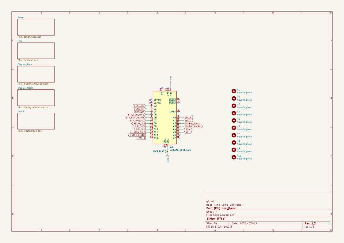
| A1 | 1 | Arduino Nano v3.x | MCU, socketed so it can be swapped without desoldering |
| U1, U4 | 2 | 74HC595 | Daisy-chained shift registers driving the segment lines |
| U2, U5 | 2 | 74HC138 | 3-to-8 decoders selecting which digit is lit |
| U3, U6 | 2 | CA56-12EWA | Common-anode 4-digit 7-segment displays (time and alarm) |
| Q1–Q8 | 8 | BC557 (PNP) | High-side drivers sourcing current into the selected digit |
| SW1 | 1 | ALPS EC11E rotary encoder w/ switch | Sets values; pressing it toggles the system on/off |
| SW2–SW4 | 3 | 6mm tactile push button | Mode, set, and manual lamp override |
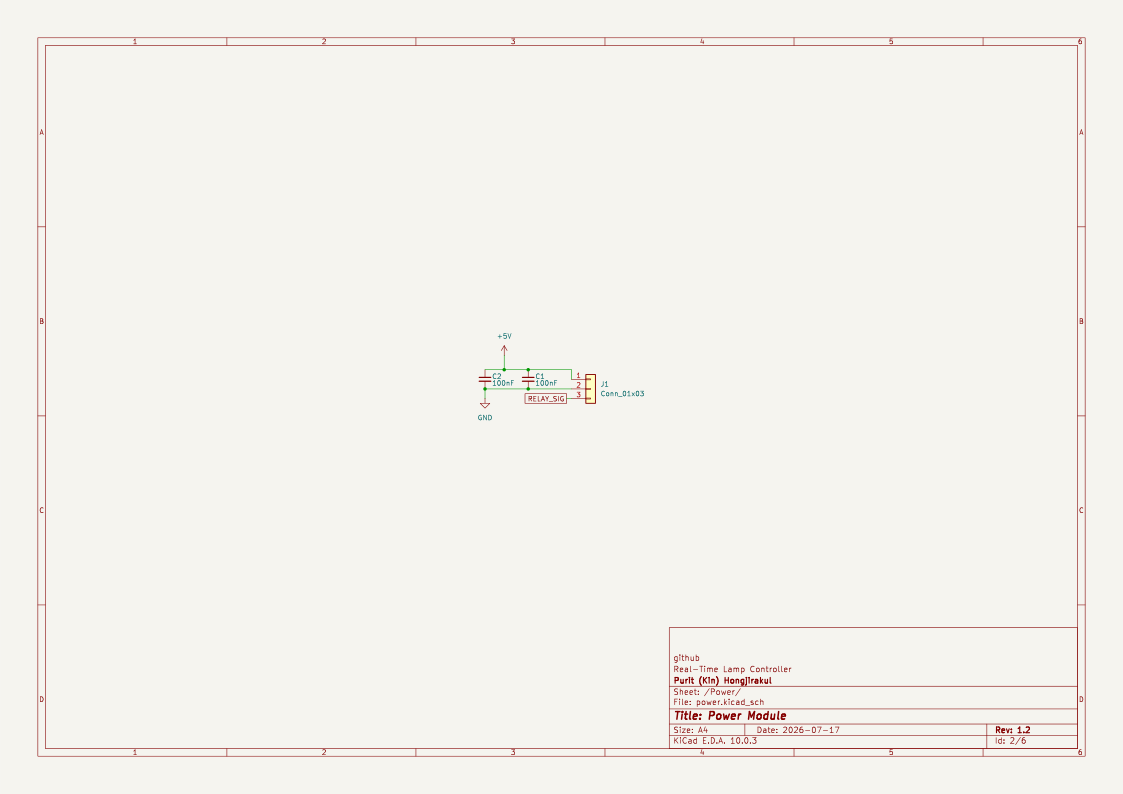
| J1 | 1 | JST-XH 1x03 | Relay / lamp output |
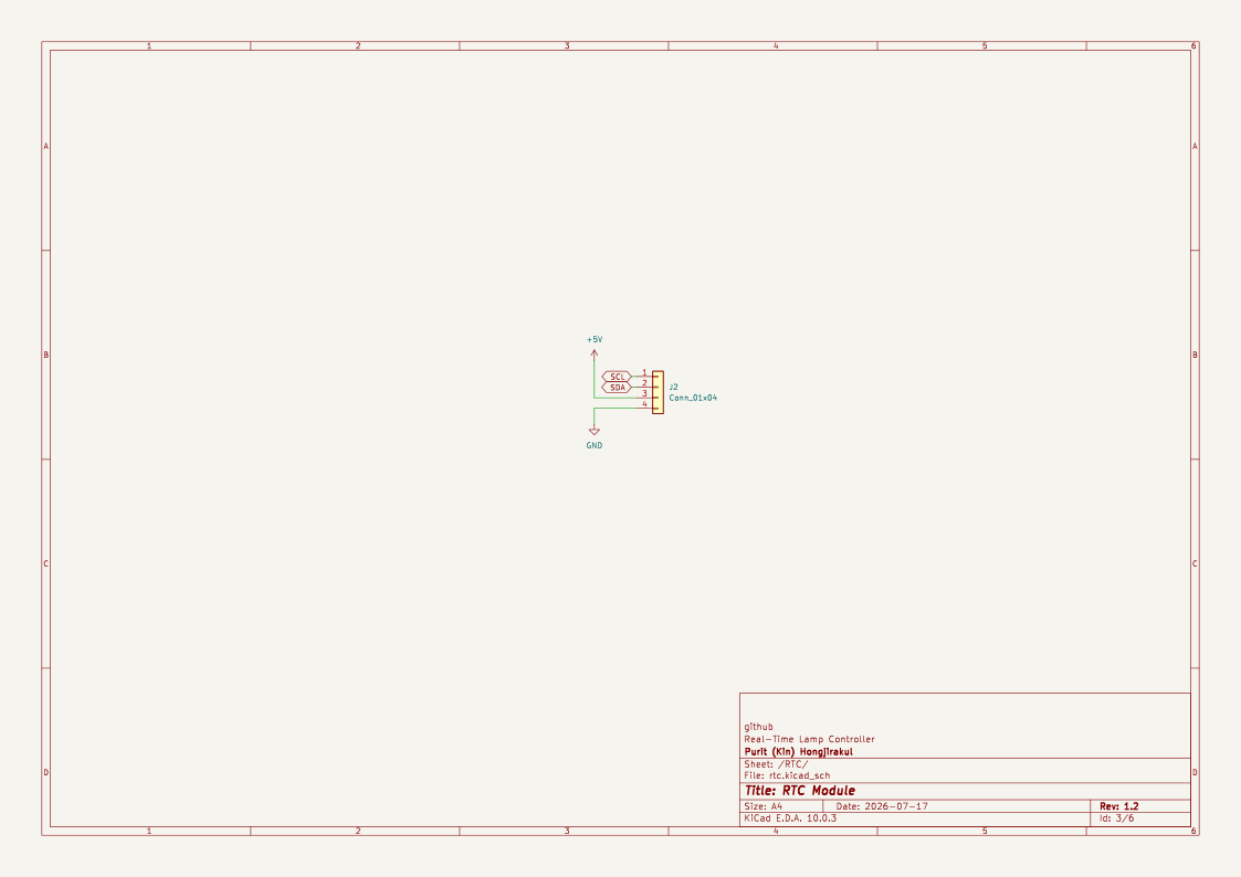
| J2 | 1 | 1x04 pin socket | DS3231 RTC module (VCC, GND, SDA, SCL) |
| R1–R6 | 6 | 10k | Pull-ups on the encoder and buttons |
| R7–R10, R27–R30 | 8 | 1k | Base resistors for the PNP digit drivers |
| R11–R26 | 16 | 330 | Segment current limiting |
| C1–C8 | 8 | 100nF | Debounce caps on the inputs, paired with the 10k pull-ups |
Full parts list: helios_bom.csv
| Qty | Value | Footprint | References |
|---|---|---|---|
| 16 | 330 | Resistor_THT:R_Axial_DIN0207_L6.3mm_D2.5mm_P7.62mm_Horizontal | R11, R12, R13, R14, R15, R16, R17, R18, R19, R20, R21, R22, R23, R24, R25, R26 |
| 8 | 100nF | Capacitor_THT:C_Disc_D5.0mm_W2.5mm_P2.50mm | C1, C2, C3, C4, C5, C6, C7, C8 |
| 8 | 1k | Resistor_THT:R_Axial_DIN0207_L6.3mm_D2.5mm_P7.62mm_Horizontal | R7, R8, R9, R10, R27, R28, R29, R30 |
| 8 | BC557 | Package_TO_SOT_THT:TO-92_Inline_Wide | Q1, Q2, Q3, Q4, Q5, Q6, Q7, Q8 |
| 6 | 10k | Resistor_THT:R_Axial_DIN0207_L6.3mm_D2.5mm_P7.62mm_Horizontal | R1, R2, R3, R4, R5, R6 |
| 6 | MountingHole | MountingHole:MountingHole_3.2mm_M3 | H1, H2, H3, H4, H9, H10 |
| 3 | SW_Push | Button_Switch_THT:SW_PUSH_6mm | SW2, SW3, SW4 |
| 2 | 74HC138 | Package_DIP:DIP-16_W7.62mm | U2, U5 |
| 2 | 74HC595 | Package_DIP:DIP-16_W7.62mm | U1, U4 |
| 2 | CA56-12EWA | Display_7Segment:CA56-12EWA | U3, U6 |
| 1 | |||
| 1 | Arduino_Nano_v3.x | Module:Arduino_Nano | A1 |
| 1 | Conn_01x03 | Connector_JST:JST_XH_B3B-XH-A_1x03_P2.50mm_Vertical | J1 |
| 1 | Conn_01x04 | Connector_PinSocket_2.54mm:PinSocket_1x04_P2.54mm_Vertical | J2 |
| 1 | MountingHole | Relay_THT:Relay_Module_5V_Mounting | H5 |
| 1 | RotaryEncoder_Switch | Rotary_Encoder:RotaryEncoder_Alps_EC11E-Switch_Vertical_H20mm | SW1 |
kyriosaa/helios
A real-time controller that automatically turns on a lamp in my room every morning based on an alarm

robsonsmartins/usbflashprog
A memory device programmer (Flash/EPROM/E2PROM) board and software, connected to PC by USB port.


felipesantiagoach-ops/cdp1802-8bit-computer
8-bit microcomputer based on the RCA CDP1802, the first CMOS microprocessor. Three stages designed in KiCad: two built and tested (assembly programs, UART, Tiny BASIC, Elf/OS) and a final design with an ADC, I²C/SPI…
It measures 149.9 × 125.7 mm and has 2 copper layers, 1.6 mm thick.
67 parts, built around the 74HC138, 74HC595 and BC557. The full list of its parts is on this page, with links to each part's symbol and footprint where PCBKit's library has them.
From the kyriosaa/helios repository on GitHub, at the commit this page was made from: the board is 2layer/helios/helios.kicad_pcb and its schematic 2layer/helios/display_alarm.kicad_sch. PCBKit opens the board in the browser, with nothing to install.
Its repository states no licence, so its author keeps all rights: ask kyriosaa before reusing the design.