
2 layers149.9 × 125.7 mm
Helios
kyriosaa/helios
A real-time controller that automatically turns on a lamp in my room every morning based on an alarm
67 parts

 kyriosaa/helios
A real-time controller that automatically turns on a lamp in my room every morning based on an alarm
Helios is an open-source printed circuit board by kyriosaa, from the kyriosaa/helios repository on GitHub. It is a 4-layer board of 149.9 × 125.7 mm with 91 parts on 96 nets, routed with 276 tracks and 34 vias.
It is built around the 74HC138, 74HC595 and CC56-12EWA, with the BC557 and DS3231S# among its other parts. Its parts include 30 resistors, 8 capacitors, 8 transistors, 6 ICs and 4 switches. It belongs with the lEDs and displays boards and the AVR (ATmega, ATtiny) boards of this library.


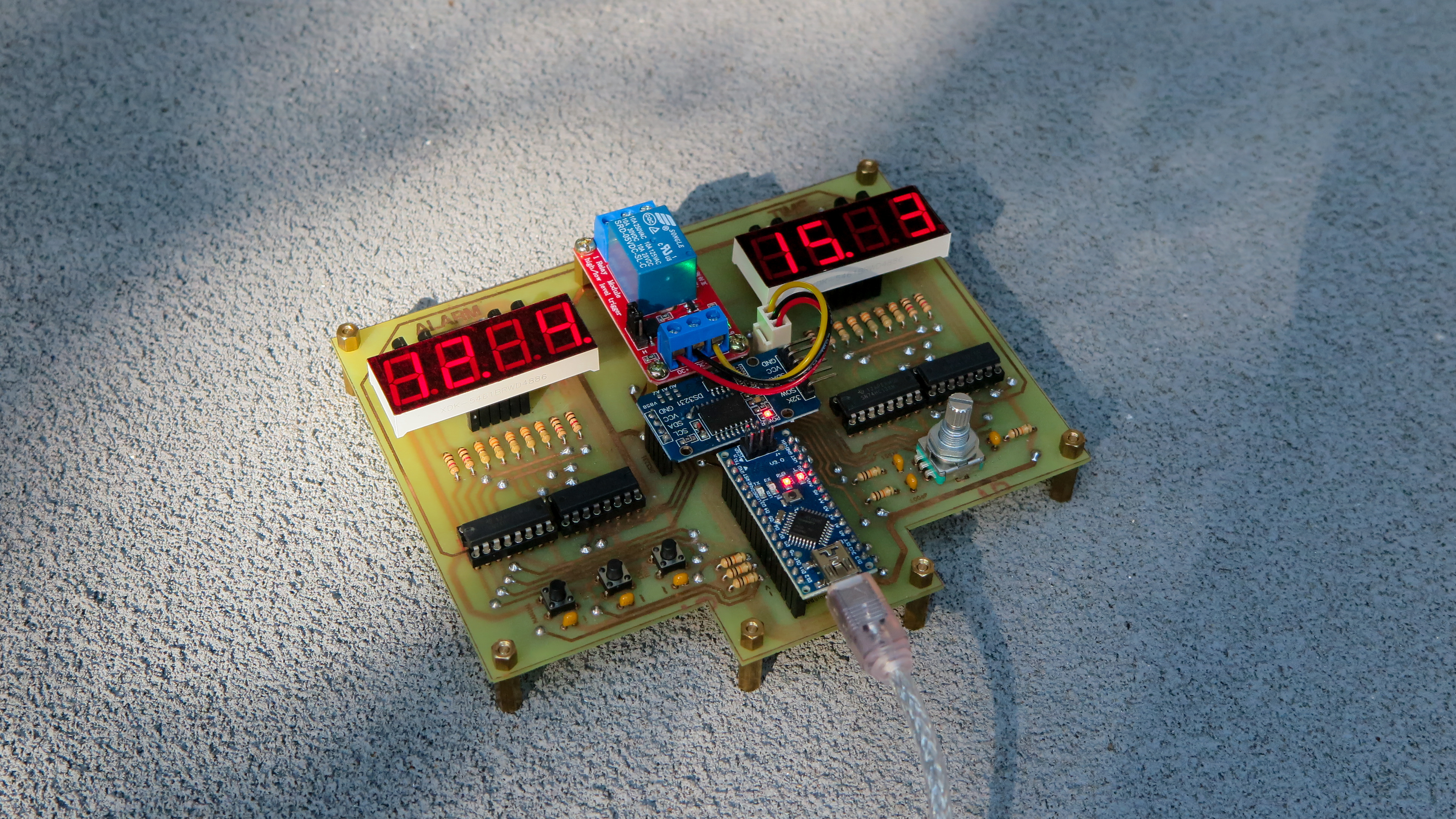


A real-time lamp controller for my room. Keeps the time (even when unplugged) and flips a relay once the clock and alarm values match.
My room doesn't have windows so I created this device to automatically turn on my bedside lamp and put myself into fight or flight every morning to help me wake up in time for work/school.
🎥 Demo Video 🎥
Some notes on why the board is built the way it is.
The RTC has its own coin-cell backup, so the clock survives a power outage or being moved to another room. Keeping time on the MCU would mean re-setting the clock every time the device lost power, which is exactly the kind of small annoyance that would make me stop using it.
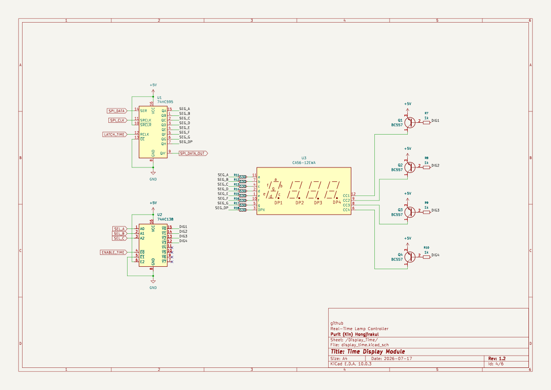
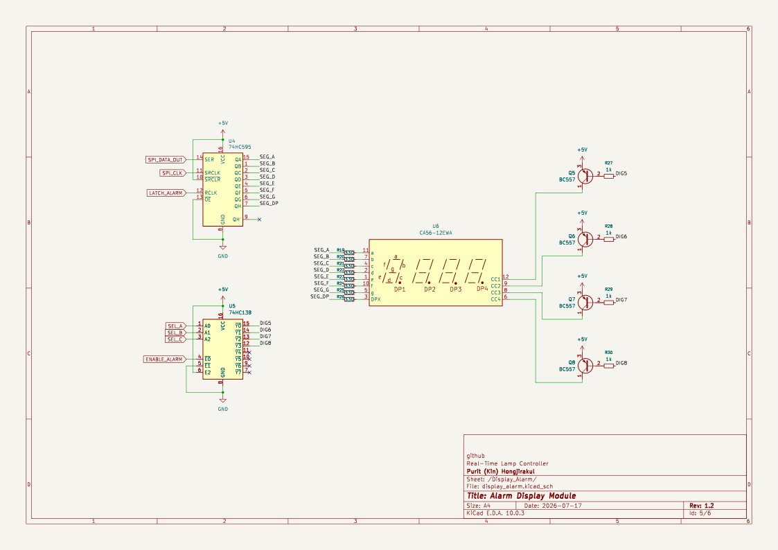
A MAX7219 or TM1637 would have done this with fewer parts and less code. I used two 74HC595s for the segments and a 74HC138 plus PNP high-side drivers per display because I to practice building the multiplexing myself instead of buying it in a chip.
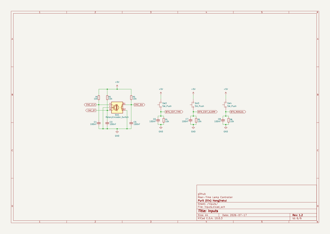
Every input has a 10k resistor and a 100nF capacitor on it to filter out switch bounce. The tradeoff to this is that signals now fade between HIGH and LOW over about a millisecond instead of snapping. During that fade, the Arduino can't really tell which one it's looking at, so a little noise makes it read HIGH-LOW-HIGH-LOW a few times before settling. An interrupt on ENC_CLK (D2) would count every one of those HIGH-LOW flips, so one click of the encoder knob would add 3 or 4 counts. However, reading the pin in the loop() function only ever sees the value after it settles, which solves the issue.
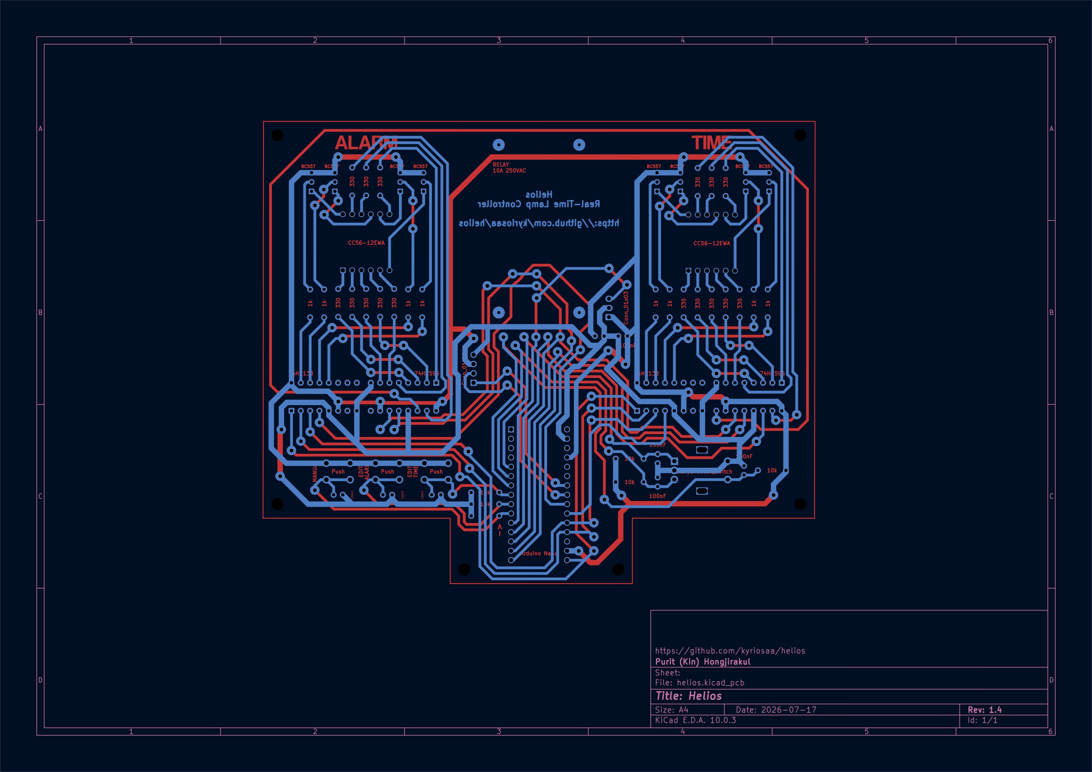
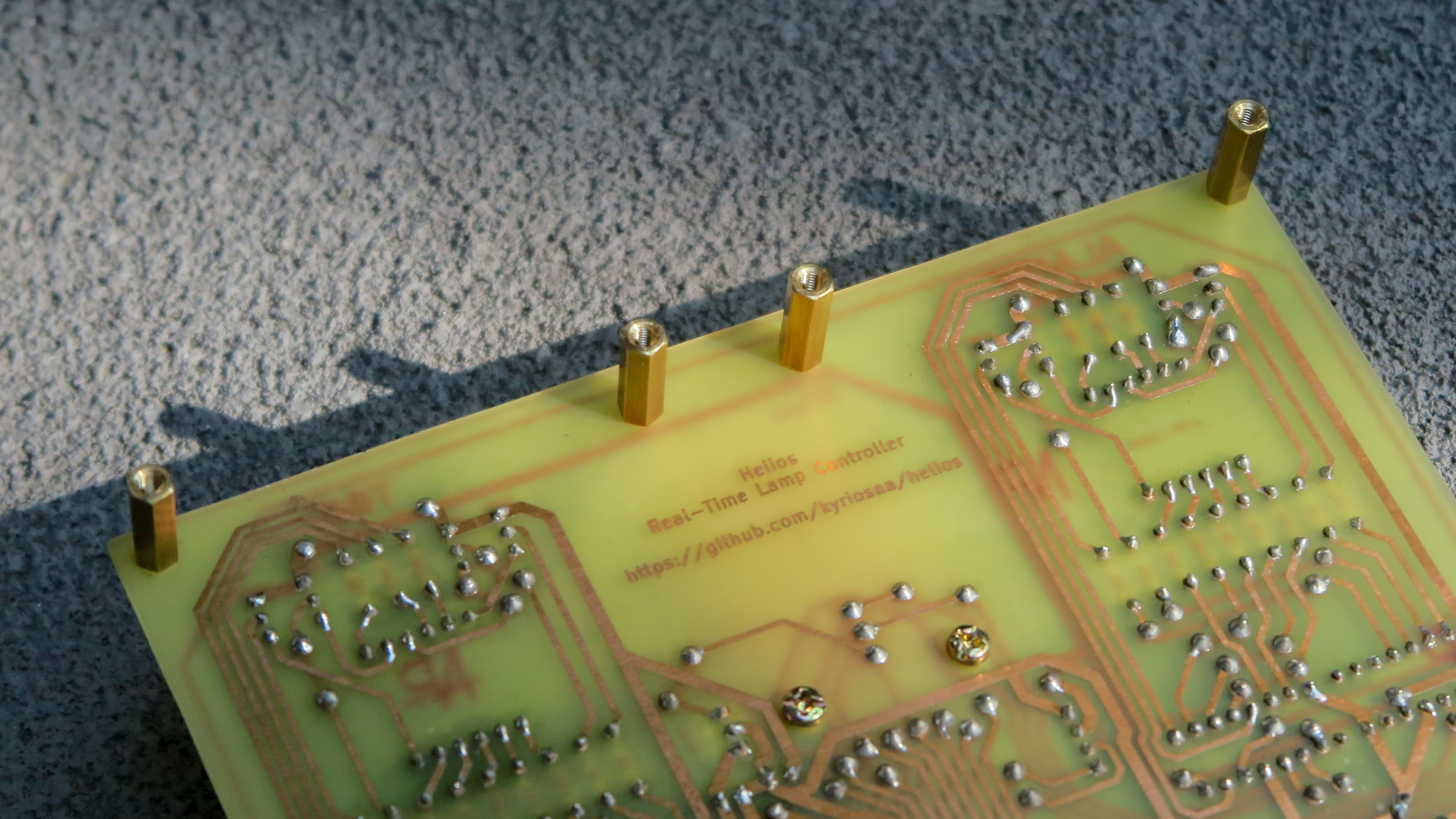
The 2-layer version is meant to be manually etched. But I know most people dont have an etching machine, so the 4-layer version is for anyone who doesn't have an etching setup and would rather send it to a manufacturer (I'm also experimenting with curved traces on the 4-layer version).
| Feature | Description |
|---|---|
| 24/7 Timekeeping | A coin battery supports the DS3231, so pulling the plug doesn't require a manual time recalibration |
| Dual Displays | Separate 7-segment displays for the current time and alarm |
| Manual Override | One button forces the lamp on and disarms the alarm. The armed state is shown by a decimal point on the alarm display |
| System ON/OFF | Pressing the encoder blanks the displays and cuts the relay |
| Multiplexed Digits | Two 74HC595s (daisy-chained) drive segments, 74HC138s + PNP high-side drivers select digits |
| Ref | Qty | Part | Role |
|---|---|---|---|
| A1 | 1 | Arduino Nano v3.x | MCU, socketed so it can be swapped without desoldering |
| U1, U4 | 2 | 74HC595 | Daisy-chained shift registers driving the segment lines |
| U2, U5 | 2 | 74HC138 | 3-to-8 decoders selecting which digit is lit |
| U3, U6 | 2 | CA56-12EWA | Common-anode 4-digit 7-segment displays (time and alarm) |
| Q1–Q8 | 8 | BC557 (PNP) | High-side drivers sourcing current into the selected digit |
| SW1 | 1 | ALPS EC11E rotary encoder w/ switch | Sets values; pressing it toggles the system on/off |
| SW2–SW4 | 3 | 6mm tactile push button | Mode, set, and manual lamp override |
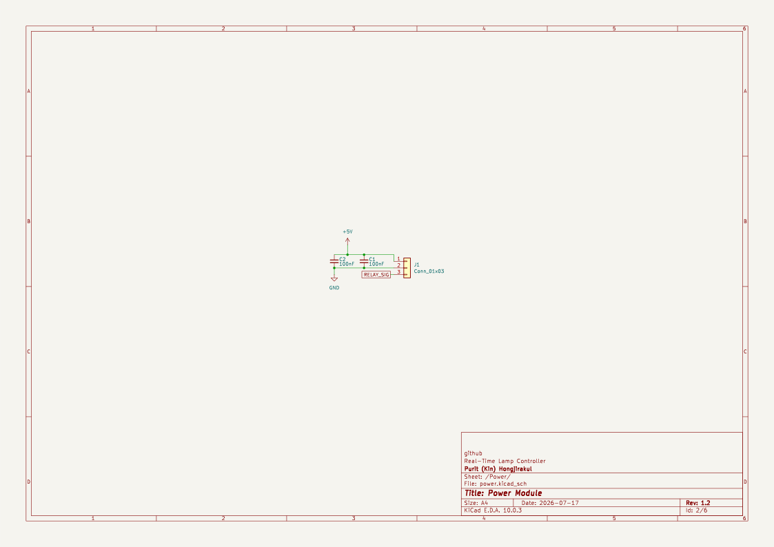
| J1 | 1 | JST-XH 1x03 | Relay / lamp output |
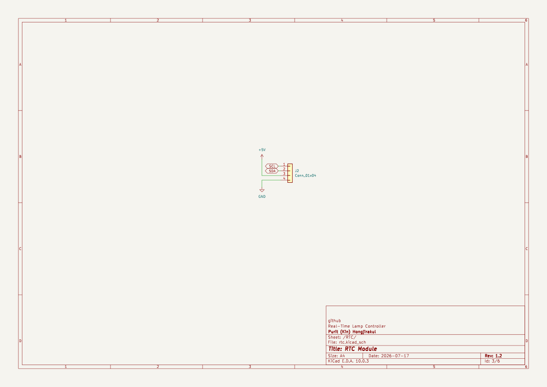
| J2 | 1 | 1x04 pin socket | DS3231 RTC module (VCC, GND, SDA, SCL) |
| R1–R6 | 6 | 10k | Pull-ups on the encoder and buttons |
| R7–R10, R27–R30 | 8 | 1k | Base resistors for the PNP digit drivers |
| R11–R26 | 16 | 330 | Segment current limiting |
| C1–C8 | 8 | 100nF | Debounce caps on the inputs, paired with the 10k pull-ups |
Full parts list: helios_bom.csv
| Qty | Value | Footprint | References |
|---|---|---|---|
| 25 | LOGO | LOGO | G***, G***, G***, G***, G***, G***, G***, G***, G***, G***, G***, G***, G***, G***, G***, G*** +9 |
| 16 | 150 | Resistor_THT:R_Axial_DIN0207_L6.3mm_D2.5mm_P7.62mm_Horizontal | R11, R12, R13, R14, R15, R16, R17, R18, R19, R20, R21, R22, R23, R24, R25, R26 |
| 8 | 100nF | Capacitor_THT:C_Disc_D5.0mm_W2.5mm_P2.50mm | C1, C2, C3, C4, C5, C6, C7, C8 |
| 8 | 1K | Resistor_THT:R_Axial_DIN0207_L6.3mm_D2.5mm_P7.62mm_Horizontal | R7, R8, R9, R10, R27, R28, R29, R30 |
| 8 | BC557 | Package_TO_SOT_THT:TO-92_Inline_Wide | Q1, Q2, Q3, Q4, Q5, Q6, Q7, Q8 |
| 6 | 10K | Resistor_THT:R_Axial_DIN0207_L6.3mm_D2.5mm_P7.62mm_Horizontal | R1, R2, R3, R4, R5, R6 |
| 6 | MountingHole | MountingHole:MountingHole_3.2mm_M3 | H1, H2, H3, H4, H9, H10 |
| 3 | SW_Push | Button_Switch_THT:SW_PUSH_6mm | SW2, SW3, SW4 |
| 2 | 74HC138 | Package_DIP:DIP-16_W7.62mm | U2, U5 |
| 2 | 74HC595 | Package_DIP:DIP-16_W7.62mm | U1, U4 |
| 2 | CC56-12EWA | Display_7Segment:CA56-12EWA | U3, U6 |
| 1 | Arduino_Nano_v3.x | Module:Arduino_Nano | A1 |
| 1 | DS3231 | Connector_PinSocket_2.54mm:PinSocket_1x04_P2.54mm_Vertical | J2 |
| 1 | MountingHole | Relay_THT:Relay_Module_5V_Mounting | H5 |
| 1 | Rotary Encoder | Rotary_Encoder:RotaryEncoder_Alps_EC11E-Switch_Vertical_H20mm | SW1 |
| 1 | To Relay | Connector_JST:JST_XH_B3B-XH-A_1x03_P2.50mm_Vertical | J1 |
kyriosaa/helios
A real-time controller that automatically turns on a lamp in my room every morning based on an alarm

SkullKill/Toy-Ikea-MicrowaveController-PCB
PCB for Microwave Controller for Ikea Kitchen DUKTIG


robsonsmartins/usbflashprog
A memory device programmer (Flash/EPROM/E2PROM) board and software, connected to PC by USB port.

It measures 149.9 × 125.7 mm and has 4 copper layers, 1.6 mm thick.
91 parts, built around the 74HC138, 74HC595, CC56-12EWA and BC557. The full list of its parts is on this page, with links to each part's symbol and footprint where PCBKit's library has them.
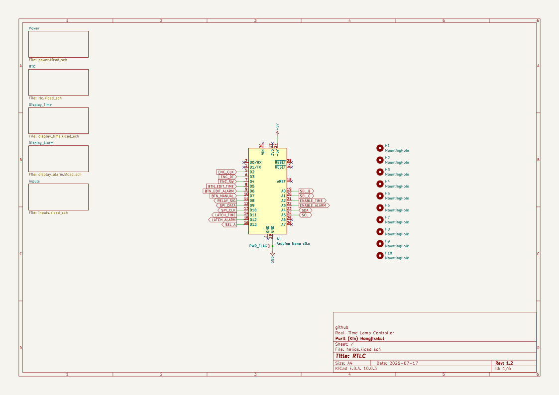
From the kyriosaa/helios repository on GitHub, at the commit this page was made from: the board is 4layer/helios/helios.kicad_pcb and its schematic 2layer/helios/display_alarm.kicad_sch. PCBKit opens the board in the browser, with nothing to install.
Its repository states no licence, so its author keeps all rights: ask kyriosaa before reusing the design.