4 layers85 × 85 mm
 KubbyDev/hen-translator
My first microcontroller PCB. A bad chicken translator
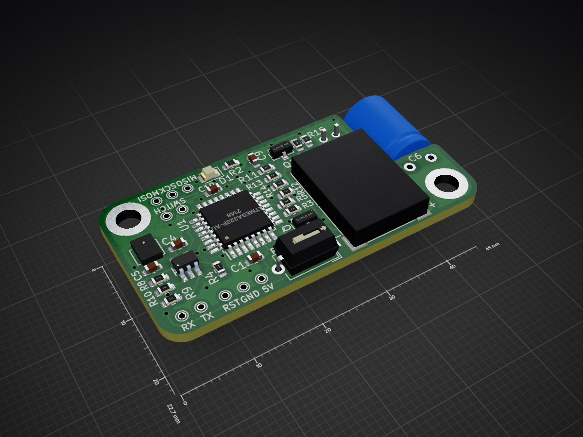
Hen translator is an open-source printed circuit board by KubbyDev, from the KubbyDev/hen-translator repository on GitHub. It is a 2-layer board of 45 × 22.7 mm with 48 parts on 43 nets, routed with 268 tracks and 53 vias.
It is built around the ATMEGA328P-AU, MCP6001UT-I/OT-HX and ICS-40181. Its parts include 15 resistors, 8 capacitors, 3 ICs, 2 transistors and 2 connectors. It belongs with the AVR (ATmega, ATtiny) boards of this library.


The goal of this project is to make a small module that can be attached around the neck of a chicken. This module listens for chicken sounds and "translates" them (it says a random sentence with a synthesized voice). This idea is dumb, I know, but I learned a lot doing it.

I made my own PCB for this project. The main concerns when selecting the components were size, power consumption and cost. All the components I used on the final board are listed here: https://github.com/KubbyDev/hen-translator/blob/main/Infos/Components.txt
To store all the audio samples, I decided to use an SD card because it's easy to load new wave files. I used a mosfet to cut power when the SD card is not needed because the board is just listening most of the time.
I used a simple 8 Ohm 0.7 Watt smd speaker to produce sounds. I added a large capacitor to filter out current spikes and a mosfet so the microcontroller can control it without powering it.
At the beginning of the project I wanted to use an Arduino Nano because I was familiar with these boards. The main problem was its size. But then I heard about the Pro Mini which is much smaller. The only catch is that it doesn't have a USB port for programming, but it's not that hard to do without. Then I did some research and saw that it's a good idea to desolder the power led and the 3.3V LDO if I don't use them because they draw power. Ok why not. But then it's easier to just buy the microcontroller and solder it into my own board. The only difficulty it adds is the bootloader that doesn't come preinstalled.
So I chose an AtMega328p, and I added through-hole test points to plug wires to burn the bootloader (SPI) and load programs (Serial). I also added a switch between the power pins of the MCU and the power rail of the rest of the board because it's 3.3V and I want to be able to program it with an Arduino (5V) without putting 5V in the 3.3V components.
My first attempt at burning the bootloader didn't work because I was using the Arduino Uno bootloader but the 1st version of the PCB was using a 10 MHz crystal oscillator. This didn't cause problems to burn the bootloader because SPI is synchronous, but then I couldn't upload sketches because the baud rates were wrong. I solved this by simply using the 8 MHz internal clock instead of my 10 MHz external crystal, and burning a bootloader made for an 8 MHz clock. I could hack a 10 MHz bootloader but now that I know the external crystal is not needed, I prefer just removing it.
My first idea was to use a 3V button battery and a boost converter to get 5V to power the microcontroller. But I wanted to use an SD card which works at 3.3V, so I had to add a 3.3V LDO from 5V or a second boost converter. This is not efficient at all. But then I saw that the AtMega328p works from 1.8V to 5.5V, so I decided to use a single boost converter to 3.3V and power everything from it. I also did some research about low voltage mode (1.8V) on SD cards but didn't find much information and it seemed like I would still have to start at 3.3V to then switch to 1.8V so I gave up this idea.
Later I realized I had another problem: the speaker draws 200 mA at 3.3V which a button battery can't provide. So I switched to a 1.5V AAA battery. But 200mA is also too much for the cheap boost converter I had found, and better boost converters are a lot more expensive. So I just connected the speaker directly to the battery so I don't need to change the converter (I had already ordered it), I can remove the resistor I had to limit current at 3.3V and I can have a higher current than if I chose a cheap regulator that I would have to run at its limits (so with a low efficiency). With this solution I get 0.3W at 1.5V.
I could switch to two 1/2 AAA 1.2V batteries. They take the same space as the 1.5V battery but have a combined output of 2.4V which forces 0.7W to pass through the speaker. But they are very expensive and the small increase in volume is not worth it.
To provide a clock to the microcontroller I wanted to use a 16 MHz quartz oscillator at first because it's what's used on Uno and Nano boards. But when I chose to power everything from 3.3V I saw that the AtMega328p has a maximum clock speed that depends on the power input voltage. At 3.3V, 16 MHz is too fast, but 10 MHz should work fine so I used a 10 MHz external oscillator.
Then, because of the bootloader problems described in the microcontroller section, I just removed it to use the internal 8 MHz oscillator.
I chose a MEMS microphone because they are cheap and very small. For the first version of the PCB I chose a PDM microphone without doing much research about it and found out later that it's very hard to read PDM from an AtMega328p...
I did a lot of research and found solutions like hacking the SPI controller to read PDM with it, using a DAC to convert PDM to analog to read it, using a low pass filter to filter out low SPL values and just triggering the translation when something comes out of the filter etc...
Eventually I just changed the PDM microphone for an analog output microphone with an operational amplifier. It was a nightmare to solder but it works well.
The first PCB had some major flaws like the microphone I couldn't read, the speaker that drew too much current and some pullup resistors that were missing on the SPI lines for the SD card. I also connected Aref to VCC instead of a capacitor to GND on the microcontroller.
The test points were too small for my wires, so I had to solder them but some of the vias detached and everything was a big mess, but I was able to learn from it and I haven't had any problem with the second version of the PCB.

To burn the bootloader, I use an Arduino Uno with the ArduinoISP example sketch connected via SPI to my PCB. To upload sketches, I use an Arduino Uno with the microcontroller removed and a Serial connection to my PCB. The procedure is detailed here: https://github.com/KubbyDev/hen-translator/blob/main/Infos/BurnBootloader.txt
The program has 3 things to do:
To play wav files I use the TMRpcm library. It's easy to use because my use case is standard.
To read data from the SD card I use the Arduino SD library (and TMRpcm does too). It works with standard 2GB SD cards but not with the cheap 512B cards I bought. I will try to fix the library but for now I just use 2GB cards.
I would like to do some cool FFT sound recognition but I don't think it will be possible on the AtMega328p mainly because it's too slow and doesn't have enough ram. For the moment I will just trigger the translation when the sound pressure level goes higher than a certain threshold.
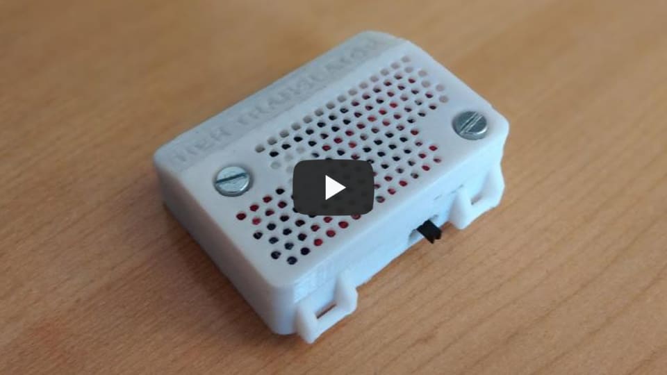
I had to learn Fusion360 for this project so the CAD could probably be way better, but it works. There are two parts. The box that goes on the chicken, and a stand because I don't actually have a chicken at home and also because this version is not reliable enough for these conditions. Everything is 3D printed in white PLA and painted.
The collar is just a box holding the board and the battery with a power switch and holes for sound to come in and out.
The stand is based on a chicken I found on Thingyverse. The interior is hollow, and contains a PCB (the same PCB, but without microphone because it's not needed), a battery, a power switch and a button to trigger a chicken sound. The button is an end of travel sensor that we can trigger by pushing on the thingy on the head of the chicken.

| Qty | Value | Footprint | References |
|---|---|---|---|
| 10 | TestPoint | Board:TestPoint_THTPad_D1.0mm_Drill0.7mm | TP1, TP2, TP3, TP4, TP5, TP6, TP7, TP8, TP9, TP10 |
| 8 | 10K | Resistor_SMD:R_0603_1608Metric | R5, R8, R9, R11, R12, R13, R14, R15 |
| 4 | 100nF | Capacitor_SMD:C_0603_1608Metric | C1, C4, C9, C10 |
| 2 | 10k | Resistor_SMD:R_0603_1608Metric | R1, R7 |
| 2 | 10uF | Capacitor_SMD:C_0805_2012Metric | C2, C3 |
| 2 | 1k | Resistor_SMD:R_0603_1608Metric | R3, R6 |
| 2 | Q_NMOS_GSD | Package_TO_SOT_SMD:SOT-23 | Q1, Q2 |
| 1 | 1000uF | Capacitor_THT:C_Radial_D8.0mm_H11.5mm_P3.50mm | C6 |
| 1 | 120 | Resistor_SMD:R_0603_1608Metric | R2 |
| 1 | 21K | Resistor_SMD:R_0603_1608Metric | R4 |
| 1 | 4.7uF | Capacitor_SMD:C_0603_1608Metric | C5 |
| 1 | 4.7uH | Inductor_SMD:L_1008_2520Metric | L1 |
| 1 | 5025700893 | Board:MOLEX_5025700893 | J1 |
| 1 | 510 | Resistor_SMD:R_0603_1608Metric | R10 |
| 1 | ATmega328P-AU | Package_QFP:TQFP-32_7x7mm_P0.8mm | U1 |
| 1 | Conn_01x02_Male | ConnectorsEvo:S02B-PASK | J2 |
| 1 | ICS-40181 | Board:MIC_ICS-40181 | MK1 |
| 1 | LOGO | Board:Logo | G*** |
| 1 | MCP6001UT-I_OT | Board:SOT95P270X145-5N | U3 |
| 1 | RED | LED_SMD:LED_0805_2012Metric | D1 |
| 1 | SW_SPST | Button_Switch_THT:SW_DIP_SPSTx01_Slide_6.7x4.1mm_W7.62mm_P2.54mm_LowProfile | SW2 |
| 1 | Speaker | Board:SPKR_CMS-151135-078S-67 | LS1 |
| 1 | TLV61225DCKR | Board:SOT65P210X110-6N | U2 |
The 46 most common of 48 parts.
It measures 45 × 22.7 mm and has 2 copper layers, 1.6 mm thick.
48 parts, built around the ATMEGA328P-AU, MCP6001UT-I/OT-HX and ICS-40181. The full list of its parts is on this page, with links to each part's symbol and footprint where PCBKit's library has them.
From the KubbyDev/hen-translator repository on GitHub, at the commit this page was made from: the board is Board/Board.kicad_pcb. PCBKit opens the board in the browser, with nothing to install.
Its repository states no licence, so its author keeps all rights: ask KubbyDev before reusing the design.


dmcke5/NucDeck
The Open Source DIY Handheld Gaming PC!


profdc9/RFBitBanger
A QRP digital transceiver created from readily available parts for off-the-grid maintenance

futureshocked/KLP4e_MCU-Datalogger
This is the repository for the "MCU Datalogger" project.