
2 layers100 × 75 mm
 koson/Electronics
Contains all Schematics/PCB files for each electrical system.
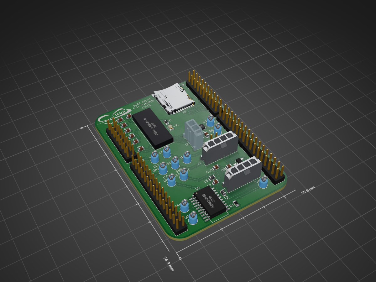
TelemetryBoard is an open-source printed circuit board by koson, from the koson/Electronics repository on GitHub. It is a 2-layer board of 55.9 × 74.9 mm with 45 parts on 122 nets, routed with 273 tracks and 19 vias.
It is built around the CDSOT23-T24CAN. Its parts include 12 capacitors, 8 connectors, 3 resistors, 3 ICs and 3 inductors.
This repo contains general information about all the electronics for the Longhorn Racing Solar team. For hardware specific details, go into their respecitve repos. PCB projects are designated by the "PCB" suffixes.
All PCBs are created in KiCad. Make sure to download the most up to date version, and select the correct OS your computer runs.
Make sure you have Git if you do not already. The command line based Git is most preferred. For the Windows version, download Git Bash.
Checklist
Cloning repos onto your machine is usually straightforwward, but our PCB project repos depend on KiCad library repos. Extra steps must be taken to correctly pull submodules. Submodules are repos that are inside a repo.
The most common way to clone repos is to use the HTTPS link, but the most secure way is to clone with SSH. The submodules use SSH, so you must generate and add an SSH key to your GitHub acoount. Follow the instructions in this tutorial. If this is your first time doing this, you can start at the Generating a new SSH key and adding it to the ssh-agent step, but reading everything is beneficial.
Once you're able to use Git with SSH, go to the green "Code" button of the repo, and click "Use SSH" to get the url link. Copy the git@hithub.com:repo-name link. Then, enter the following command to the terminal but with the correct url link:
git clone --recurse-submodules git@github.com:repo-nameIf you already cloned the repo but don't have the submodules, enter the following commands:
git submodule init
git submodule update --remoteThese rules apply to all repos. Commit and push frequently and do NOT work in the master branch!!
Each PCB project has its own repo. The naming convention is System-Function: System is the system of the car that it relates to, such as Controls, BPS, etc. and Function is the name/functionality of the board you're making. Discuss with the leads if you are having trouble with the naming convention.
Each PCB project may/will use components which are not available by default in the KiCad standard libraries. Standardized components that are integrated across all systems are in the UTSVT-KiCadLibraries repo. You will need to create a submodule (essentially adding a repo inside a repo) to prevent library dependency issues. Look at existing PCB repos for examples. For more information on adding submodules to your repo, here is some useful documentation.
Whenever you create a KiCad project, make sure to add all the symbol and footprint libraries into the Project Specific Libraries. This will prevent library dependency errors whenever another member opens the project that doesn't have any libraries configured.
Before you make an edit or add anything to a repo, make sure to be in your own branch. The master branch contains the most stable version of the hardware/software, and any edits or additions that are made must be reviewed and approved before the master branch is updated.
Commit and push frequently into your own branches or else there is no point in having version control.
Everything that is created or edited must be reviewed. Once you've completed your edits or additions inside your own branch, create a Pull Request (PR) in GitHub. Add a description of your project and what you've done in your PR. Assign reviewers to the PR.
Talk to your leads on who can review your PR. You may assign multiple people to review your project.
Reviewers will add comments into the PRs if there is anything that should be updated. This will keep a record and allows everyone to be informed.
These rules exist to make the all the hardware streamlined and consistent.
Each board must have a version number on the top silkscreen layer.
Each board must have a version number vX.Y: X signifies a new design/feature has been added to the board, and Y signifies minor fixes such as trace fixes, pin connection fixes, component rearrangement, etc. Each board's version number is independent of any other board. Read the Board Dependencies: VERSION.md section for information if boards are dependent on each other.
Some systems will have boards that depend on other boards e.g. the BPS-LeaderPCB depends on the BPS-MinionPCB, BPS-AmperesPCB, and the BPS-FanPCB. As updates and changes are made to individual boards, newer versions may become incompatible with other older boards. A VERSION.md file should be created and placed inside the PCB repos if board dependencies exist. The VERSION.md in this repo is a template that you can copy. Check other existing repos for more examples.
Create issue tickets in this repo for any general electrical related todos or discussions. For project specific questions e.g. deciding a component for a PCB, create the tickets inside their respective repo.
| Position | Name | What can they help you with? |
|---|---|---|
| Electrical Lead | Chase Block | Everything |
| Hardware Lead | Hannah Lee | Everything |
| Array/MPPT Lead | Matthew Yu | Array or MPPT related hardware |
| BPS Lead | Clark Poon | BPS or Battery related hardware |
| Controls Lead | Rishi Ponnekanti | Motor, Dashboard, or Controls related hardware |
| Data Acq. Lead | Colette Montminy | Telemetry related hardware |
| pleb | Sijin Woo | Git or general topics |
I cloned a PCB repo, but I'm getting errors from the symbols and footprint libraries when I open the KiCad project. What should I do?
Each KiCad project has its own project specific libraries which the electrical team manages. Most likely the submodules were not pulled when you cloned the repo. Enter the following commands:
git submodule init
git submodule update --remote
I'm getting detached HEAD error in the submodule directory. How do I fix this?
Call
git submodule update --remote. If anything in the submodules were updated or changed, then you'll need to update your repo to point to the most recent commit ID. In the top level of your repo (NOT in the submodule directory), commit and push.
| Qty | Value | Footprint | References |
|---|---|---|---|
| 3 | .1u | Capacitor_SMD:C_0805_2012Metric | C1, C4, C9 |
| 3 | 10u | Capacitor_SMD:C_0805_2012Metric | C3, C8, C11 |
| 2 | .01u | Capacitor_SMD:C_0805_2012Metric | C2, C10 |
| 2 | 100u | Capacitor_SMD:C_0805_2012Metric | C5, C12 |
| 2 | 2k | Inductor_SMD:L_0805_2012Metric | L2, L3 |
| 2 | Conn_01x04 | Connector_Molex:Molex_Micro-Fit_3.0_43650-0415_1x04_P3.00mm_Vertical | J4, J5 |
| 1 | .22u | Capacitor_SMD:C_0805_2012Metric | C7 |
| 1 | 0 | Resistor_SMD:R_0805_2012Metric | R1 |
| 1 | 120 | Resistor_SMD:R_0805_2012Metric | R2 |
| 1 | 12VIN | TestPoint:TestPoint_Keystone_5005-5009_Compact | TP3 |
| 1 | 12V_GND | TestPoint:TestPoint_Keystone_5005-5009_Compact | TP4 |
| 1 | 3k | Resistor_SMD:R_0805_2012Metric | R3 |
| 1 | 47u | Capacitor_SMD:C_0805_2012Metric | C6 |
| 1 | 5u | Inductor_SMD:L_TDK_NLV32_3.2x2.5mm | L1 |
| 1 | 9VIN | TestPoint:TestPoint_Keystone_5005-5009_Compact | TP13 |
| 1 | 9V_GND | TestPoint:TestPoint_Keystone_5005-5009_Compact | TP14 |
| 1 | ADM3055E | UTSVT_ICs:SOIC-20W_7.5x15.4mm_Pitch1.27mm | U2 |
| 1 | CAN_H | TestPoint:TestPoint_Keystone_5005-5009_Compact | TP9 |
| 1 | CAN_ISO_GNDIN | TestPoint:TestPoint_Keystone_5005-5009_Compact | TP7 |
| 1 | CAN_ISO_GNDOUT | TestPoint:TestPoint_Keystone_5005-5009_Compact | TP8 |
| 1 | CAN_ISO_VIN | TestPoint:TestPoint_Keystone_5005-5009_Compact | TP5 |
| 1 | CAN_ISO_VOUT | TestPoint:TestPoint_Keystone_5005-5009_Compact | TP6 |
| 1 | CAN_L | TestPoint:TestPoint_Keystone_5005-5009_Compact | TP10 |
| 1 | CAN_RD | TestPoint:TestPoint_Keystone_5005-5009_Compact | TP2 |
| 1 | CAN_TD | TestPoint:TestPoint_Keystone_5005-5009_Compact | TP1 |
| 1 | CDSOT23-T24CAN | Package_TO_SOT_SMD:SOT-23W_Handsoldering | U4 |
| 1 | Conn_01x02 | Connector_Molex:Molex_Micro-Fit_3.0_43650-0215_1x02_P3.00mm_Vertical | J2 |
| 1 | Conn_02x08_Odd_Even | Connector_PinHeader_2.54mm:PinHeader_2x08_P2.54mm_Vertical | J6 |
| 1 | Conn_02x10_Odd_Even | Connector_PinHeader_2.54mm:PinHeader_2x10_P2.54mm_Vertical | J8 |
| 1 | Conn_02x15_Odd_Even | Connector_PinHeader_2.54mm:PinHeader_2x15_P2.54mm_Vertical | J7 |
| 1 | Conn_02x17_Odd_Even | Connector_PinHeader_2.54mm:PinHeader_2x17_P2.54mm_Vertical | J9 |
| 1 | Jumper | Connector_PinHeader_2.54mm:PinHeader_1x02_P2.54mm_Vertical | JP1 |
| 1 | LED | LED_SMD:LED_0805_2012Metric | D1 |
| 1 | LOGO | UTSVT_Special:UTSVT_Logo_Symbol | G*** |
| 1 | LOGO | UTSVT_Special:Hallock_Image_Small | G*** |
| 1 | Micro_SD_Card_Det | Connector_Card:microSD_HC_Hirose_DM3AT-SF-PEJM5 | J3 |
| 1 | PQMC3-Dx-Sx-S | UTSVT_ICs:CUI_PQMC3-S | U3 |
It measures 55.9 × 74.9 mm and has 2 copper layers, 1.6 mm thick.
45 parts, built around the CDSOT23-T24CAN. The full list of its parts is on this page, with links to each part's symbol and footprint where PCBKit's library has them.
From the koson/Electronics repository on GitHub, at the commit this page was made from: the board is Telemetry/TelemetryBoard/TelemetryBoard.kicad_pcb. PCBKit opens the board in the browser, with nothing to install.
Its repository states no licence, so its author keeps all rights: ask koson before reusing the design.


koson/Electronics
Contains all Schematics/PCB files for each electrical system.

koson/Electronics
Contains all Schematics/PCB files for each electrical system.

koson/Electronics
Contains all Schematics/PCB files for each electrical system.


koson/Electronics
Contains all Schematics/PCB files for each electrical system.


lhr-solar/Power-Generation-Curve-Tracer
The current maintainer of this project is Matthew Yu as of 05/20/2023. His email is matthewjkyu@gmail.com.

corbosiny/SolarCar
All code relating to solar car like: BPS, telemetry, web dev, and more.

lhr-solar/PS-BPSLeader
Reads voltage, temperature, and current of the main battery pack from the Segment Monitoring Board and HV Carrier boards to ensure the battery remains in a safe state.

dimembermatt/MPPT-Design
Design and documentation of a custom MPPT for LHR Solar. Created in part with Professor Alex Hanson's ECE 394J Power Electronics Class.


bartkepl/CanGeigerProbe
Polowa sonda promieniowania jonizującego z miniaturową lampą Geigera-Müllera, komunikująca się cyfrowo przez CAN 2.0B.

bartkepl/CanGnssNode
Polowy węzeł pozycyjny z modułem GNSS Quectel L76-L (GPS/GLONASS/Galileo/QZSS) i czujnikiem orientacji (akcelerometr + magnetometr), komunikujący się cyfrowo przez CAN 2.0B.

desvandi/PLTSMonitoring_Firmware-Backend
Integrated to PLTSMonitoring_PWA