

2 layers264 × 124.5 mm
Gateway node dev board
koko69420/HomeBus
Hard wired home automation, based on a RSICV MCU and RS-422 communication protocol
152 parts

 koko69420/HomeBus
Hard wired home automation, based on a RSICV MCU and RS-422 communication protocol
Expanders is an open-source printed circuit board by koko69420, from the koko69420/HomeBus repository on GitHub. It is a 2-layer board of 248.1 × 172.1 mm with 180 parts on 52 nets, routed with 2,260 tracks and 0 vias.
It is built around the MAX491EPD and 74HC165D. Its parts include 120 connectors and 60 ICs. It belongs with the home automation and IoT boards of this library.
The HomeBus Base Node is the primary in-wall actuator and sensor module in the HomeBus distributed automation network. Designed to fit into standard residential switch flush boxes behind wall plates, it interfaces physical toggle switches and rotary encoders with the HomeBus RS-422 serial bus while driving external relay modules to switch lights, appliances, and inductive loads.
| Front View (Component Side) | Back View (Connector Side) |
|---|---|
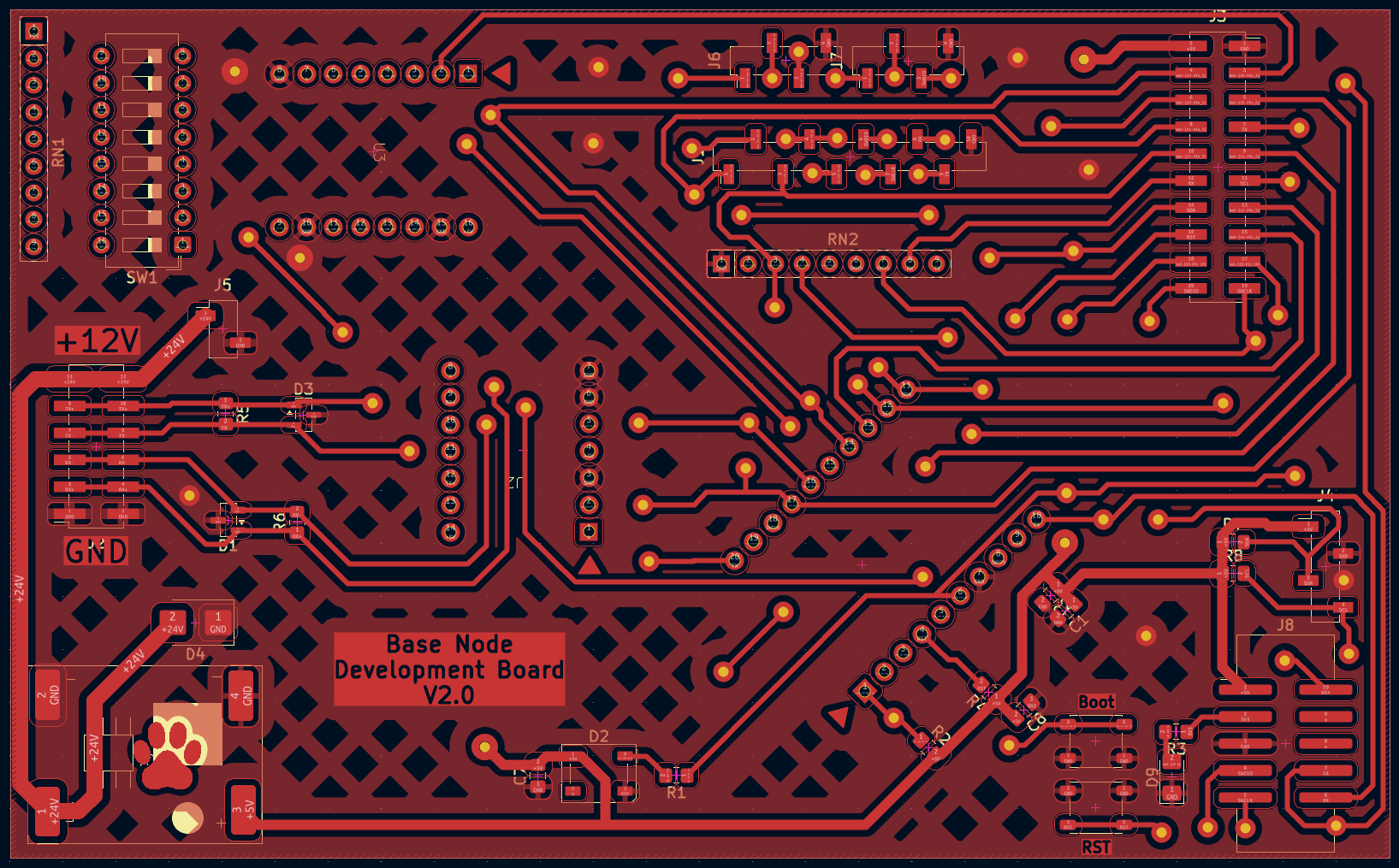 | 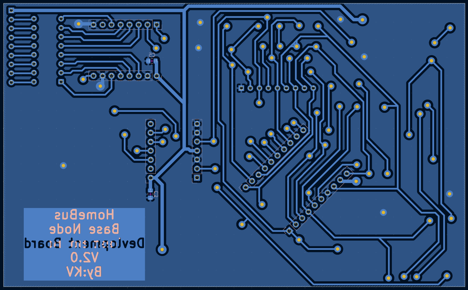 |
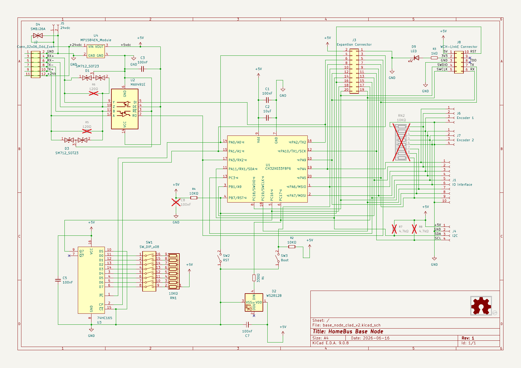
flowchart LR
    subgraph Power ["Power Subsystem"]
        BUS_IN["24V DC Bus Rail"] --> BUCK["MP1584EN Buck Converter\n(24V -> 5V DC @ 3A)"]
        BUCK --> VDD["5V Logic Rail"]
    end

    subgraph BusInterface ["RS-422 Interface"]
        RS422["XY2500 6-Pin Bus Header\n(24V, GND, TX±, RX±)"]
        TVS["SM712 TVS Array\n(-7V to +12V Protection)"]
        XCVR["MAX491 Transceiver\n(Full-Duplex RS-422)"]
        RS422 <--> TVS <--> XCVR
    end

    subgraph Processing ["Core MCU"]
        MCU["WCH CH32X033F8P6\n(32-bit QingKe RISC-V @ 48 MHz)"]
    end

    subgraph Inputs ["Input Subsystem"]
        DIP["8-Bit DIP Switch\n(Hardware Node ID)"]
        WALL["External Wall Switches /\nRotary Encoders (JST-PH)"]
        SR["74HC165D Shift Register\n(8-bit PISO Shift Register)"]
        DIP --> SR
        WALL --> SR
end| Subsystem | Component | Package | Function / Rationale |
|---|---|---|---|
| Microcontroller | WCH CH32X033F8P6 | TSSOP-20 | QingKe 32-bit RISC-V V4C core @ 48 MHz, 62 KB Flash, 20 KB SRAM. Handles RS-422 protocol stack, switch debouncing, and relay actuation. |
| Transceiver | Maxim MAX491CSD / MAX491ESD | SOP-14 | High-speed, full-duplex RS-422/RS-485 differential transceiver. Allows simultaneous transmit and receive with no collision backoff. |
| Input Multiplexer | NXP / TI 74HC165D | SOP-16 | 8-bit Parallel-In Serial-Out (PISO) shift register. Samples the 8-bit DIP switch and wall inputs using only 3 MCU pins (PL_, CP, Q7). |
| Power Converter | Monolithic Power MP1584EN | Modular Module | 3A high-frequency step-down switching buck regulator module converting centralized 24V bus power to regulated 5V system logic. |
| Surge Protection | ProTek SM712 / PSM712 | SOT-23 | Asymmetrical bidirectional TVS diode array (-7V to +12V) specifically engineered for RS-422 lines against ESD, EFT, and power transients. |
| Status Indicator | Xinglight XL-1010RGBC (WS2812B-1010) | SMD-1010 (1.0x1.0mm) | Ultra-compact single-wire addressable RGB LED for status indication, network link health, and commissioning feedback. |
| Hardware ID | 8-Position SPST DIP Switch | 2.54mm Pitch Slide | Configures physical Node ID (1–255) for commissioning, telemetry, and OTA management. |
The Base Node assigns the 20 pins of the CH32X033F8P6 as follows, differentiating between Development mode (SWD debug available) and Production mode (SWD pins repurposed for actuator GPIOs):
| Pin # | MCU Pin | Production Function | Development Function | Net / Description |
|---|---|---|---|---|
| 1 | PA0 / PC3 | GPIOC 3 | Boot Switch | Actuator Output 3 in Production; Bootloader entry trigger in Development |
| 2 | PA1 / PC4 | GPIOC 4 | GPIOC 4 | Actuator Output 4 / Relay drive line |
| 3 | PA2 / PC2 | GPIOC 2 | GPIOC 2 | Actuator Output 2 / Relay drive line |
| 4 | NRST | RST | RST | Hardware Reset line (active low, with pull-up) |
| 5 | PB0 / PC0 | HC165 Q7 | HC165 Q7 | Shift Register Serial Data Out (MISO stream to MCU) |
| 6 | PB1 | Neopixel | Neopixel | High-speed single-wire NRZ serial data stream to WS2812B LED |
| 7 | VSS | GND | GND | System Ground (0V reference) |
| 8 | PB2 / PC6 | GPIOC 6 | SWDIO | Actuator Output 6 in Production; WCH SWD Debug Data in Development |
| 9 | VDD | VDD | VDD | Logic Supply Rail (+5V DC from MP1584EN) |
| 10 | PB3 / PC8 | GPIOC 8 | SWD RX | Actuator Output 8 in Production; Debug UART RX in Development |
| 11 | PB6 | I2C SDA | I2C SDA | I2C Serial Data line for auxiliary sensor daughterboards |
| 12 | PB7 | I2C SCL | I2C SCL | I2C Serial Clock line for auxiliary sensor daughterboards |
| 13 | PB4 / PC5 | GPIOC 5 | GPIOC 5 | Actuator Output 5 / Relay drive line |
| 14 | PB5 | HC165 PL_ | HC165 PL_ | 74HC165 Asynchronous Parallel Load (active low) |
| 15 | PB8 | HC165 CP | HC165 CP | 74HC165 Shift Register Clock Pulse |
| 16 | PB10 | MAX491 DI | MAX491 DI | RS-422 Driver Input (MCU UART TX to RS-422 differential bus) |
| 17 | PB11 | MAX491 RO | MAX491 RO | RS-422 Receiver Output (RS-422 differential bus to MCU UART RX) |
| 18 | PB9 / PC7 | GPIOC 7 | SWCLK | Actuator Output 7 in Production; WCH SWD Clock in Development |
| 19 | PA3 / PC1 | GPIOC 1 | GPIOC 1 | Actuator Output 1 / Relay drive line |
| 20 | PA4 / PC9 | GPIOC 9 | SWD TX | Actuator Output 9 in Production; Debug UART TX in Development |
base_node (v1.0): Initial prototype layout. Used orthogonal 45° routing and tested basic connectivity between the CH32X033 and MAX491.base_node-rounded (v1.1): Experimental PCB layout with circular/curved track fillets using KiCad round-tracks plugin for aesthetic evaluation and high-speed trace continuity.base_node_clad (v1.2): Added continuous solid copper pour cladding across top and bottom layers, significantly reducing ground impedance and improving EMI containment in high-noise AC environments.base_node_clad_v2 (v2.0 - Production):
Basenode_gerber/.Basenode_gerber/base_node.zip.base_node_clad_v2-F_Cu.pdfbase_node_clad_v2-B_Cu.pdfbase_node_clad_v2-Edge_Cuts.pdf| Qty | Value | Footprint | References |
|---|---|---|---|
| 40 | Conn_01x07_Pin | Connector_PinHeader_2.54mm:PinHeader_1x07_P2.54mm_Vertical | J3, J3, J3, J3, J3, J3, J3, J3, J3, J3, J3, J3, J3, J3, J3, J3 +24 |
| 40 | Conn_01x08_Pin | Connector_PinHeader_2.54mm:PinHeader_1x08_P2.54mm_Vertical | J5, J5, J5, J5, J5, J5, J5, J5, J5, J5, J5, J5, J5, J5, J5, J5 +24 |
| 40 | Conn_01x10_Pin | Connector_PinHeader_2.54mm:PinHeader_1x10_P2.54mm_Vertical | J1, J1, J1, J1, J1, J1, J1, J1, J1, J1, J1, J1, J1, J1, J1, J1 +24 |
| 20 | 74HC165 | HomeBus:SOIC-16_3.9x9.9mm_P1.27mm | U3, U3, U3, U3, U3, U3, U3, U3, U3, U3, U3, U3, U3, U3, U3, U3 +4 |
| 20 | MAX491E | HomeBus:SOIC-14_3.9x8.7mm_P1.27mm | U2, U2, U2, U2, U2, U2, U2, U2, U2, U2, U2, U2, U2, U2, U2, U2 +4 |
| 20 | ~ | HomeBus:TSSOP-20-1EP_4.4x6.5mm_P0.65mm_EP2.15x3.35mm | U1, U1, U1, U1, U1, U1, U1, U1, U1, U1, U1, U1, U1, U1, U1, U1 +4 |
koko69420/HomeBus
Hard wired home automation, based on a RSICV MCU and RS-422 communication protocol

koko69420/HomeBus
Hard wired home automation, based on a RSICV MCU and RS-422 communication protocol

koko69420/HomeBus
Hard wired home automation, based on a RSICV MCU and RS-422 communication protocol

koko69420/HomeBus
Hard wired home automation, based on a RSICV MCU and RS-422 communication protocol

koko69420/HomeBus
Hard wired home automation, based on a RSICV MCU and RS-422 communication protocol

skumlos/bkm-10rlternative
Project aiming to replicate the BKM-10R/11R remote for Sony professional CRT monitors.

GadgetReboot/GR_ISO_Board
Isolation breakout board with a 5V isolated DC-DC converter, optocouplers, Relay, and more.

shanteacontrols/OpenDeck
A platform for building interactive control and sensing devices using MIDI and OSC built with Zephyr RTOS.

slu4coder/Minimal-64x4-Home-Computer
My DIY TTL home computer with VGA and PS/2 and 4x the processing power of a Commodore C64 or Apple II.

slu4coder/Minimal-UART-Computer-1-2
Legacy: Version 1 and 2 of my TTL-only CPU featuring UART I/O, an expansion port, 512KB SSD at up to 10MHz clock speed


westlicht/performer-hardware
PER|FORMER Eurorack Sequencer - Hardware Design Files

slu4coder/Minimal-64-Home-Computer
Legacy: Full TTL-only home computer with VGA and PS/2 and twice the processing power of a Commodore 64
It measures 248.1 × 172.1 mm and has 2 copper layers, 1.6 mm thick.
180 parts, built around the MAX491EPD and 74HC165D. The full list of its parts is on this page, with links to each part's symbol and footprint where PCBKit's library has them.
From the koko69420/HomeBus repository on GitHub, at the commit this page was made from: the board is Hardware/Expanders/Expanders.kicad_pcb and its schematic Hardware/Expanders/Expanders.kicad_sch. PCBKit opens the board in the browser, with nothing to install.
Its repository states no licence, so its author keeps all rights: ask koko69420 before reusing the design.