

2 layers60 × 80 mm

 kiu/xcb-20241
Cross Communication Badge to gamify conference encounters
Xcb-2024-top revb panel-4x1 is an open-source printed circuit board by kiu, from the kiu/xcb-2024 repository on GitHub. It is a 2-layer board of 249 × 95 mm with 244 parts on 376 nets, routed with 1,992 tracks and 176 vias.
It is built around the TC233A, AHT20 and IRM-H638J7/TR2, with the LR6206B-U33 among its other parts. Its parts include 60 capacitors, 52 resistors, 40 ICs, 20 connectors and 8 diodes. It belongs with the lEDs and displays boards and the STM32 boards of this library.


The cross communication badge (xcb) was created for a two day internal company conference. Its main purpose was to gamify communication and networking across the 150 participants.
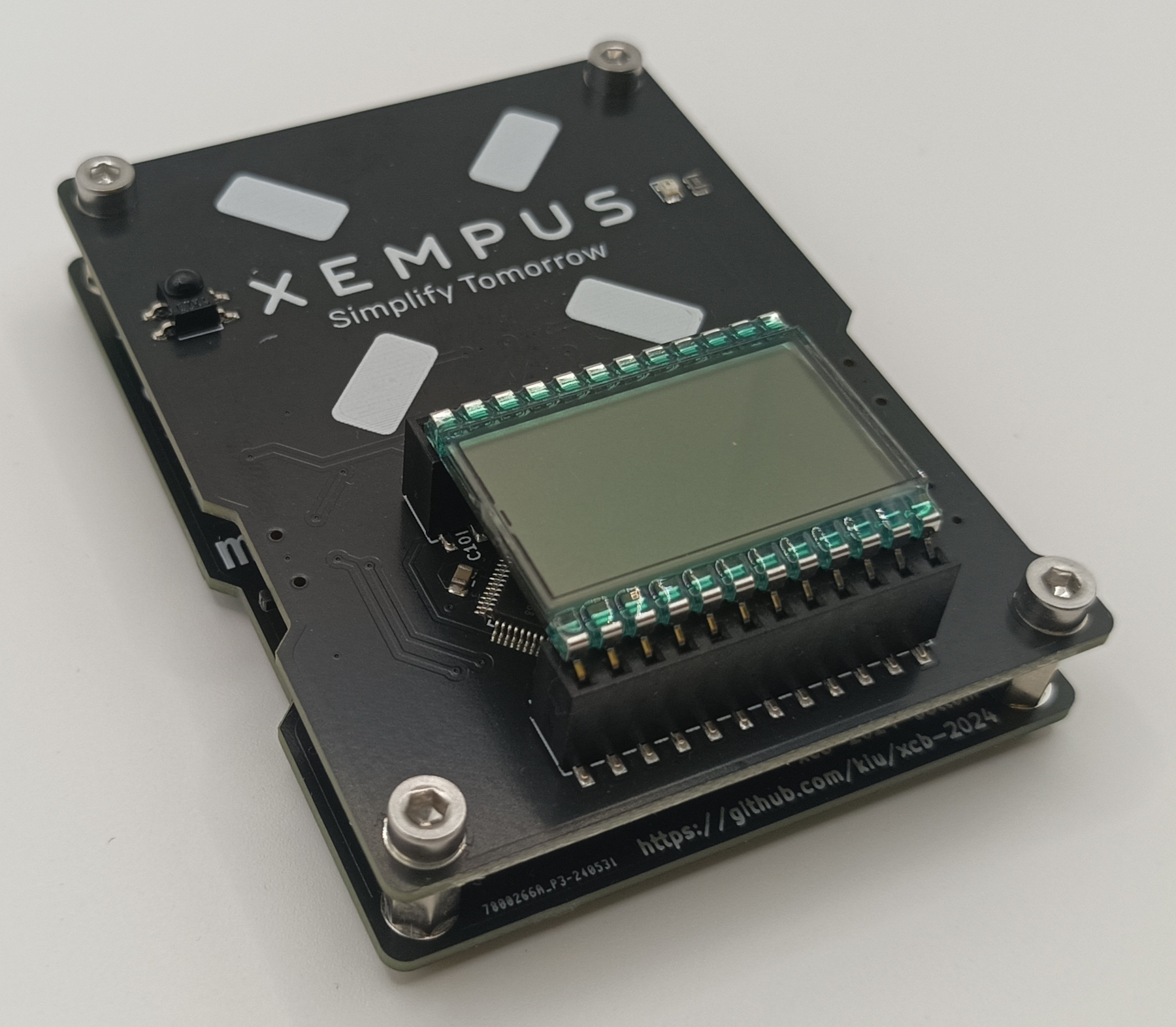
Additional images can be found in the img directory
The badge features three modes: Conference, Play and Sensor.
In conference mode each badge transmits its unique ID every 30 seconds. Any badge receiving two transmissions from the same badge within 100 seconds will count this as a unique contact. Due to limited infrared power, close proximity between sender and receiver is assumed. The amount of unique contacts is displayed on the LCD screen to gamify in-person encounters.
In addition secret badges are hidden at the event location, offering a treasure hunt for those who want to explore beyond the main conference tracks. The needed hints are printed on flyers handed out with the badge. The discovery of these secret badges is encoded in the display as single segments to easily compare progress between participants.
It was important to me that the badge could be re-used after the conference so I added two additional modes.
In play mode the badge features a version of the popular game Simon https://en.wikipedia.org/wiki/Simon_(game) (in Germany known as Senso https://de.wikipedia.org/wiki/Senso_(Spiel)). People can chase a high score, which can also be displayed when in conference mode.
In sensor mode the badge transforms into a temperature and humidity display with min/max functionality. Powered by USB the badge can continue to operate in the home or office.
On the back of this stacked PCB assembly (preventing any electrical shorts while wearing) the participants can find a silk screened word puzzle containing the names of the employees of the company.
There is a short video highlighting all badge features on youtube: https://youtu.be/XA52-lHTVL4
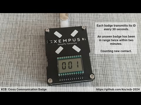
The hardware is straight forward. Powered by two CR2032 coin cells or USB, a STM32, a three digit LCD display, an infrared receiver/transmitter, a buzzer, four capacitive touch buttons and a temperature and humidity sensor. All neatly packed into a wearable badge.
This project is licensed under the Creative Commons Attribution-NonCommercial 3.0 Unported (CC BY-NC 3.0) license. Use of the company name and company logo in any form is not covered by this license.
Thanks to Fabian for helping out on the flyer design and Andrii, Maria (+Sebastian), Monika, Niels (+Milla) for working hard doing the final mechanical assembly!
| Qty | Value | Footprint | References |
|---|---|---|---|
| 28 | 4k7 | Resistor_SMD:R_0805_2012Metric | R2, R2, R2, R2, R3, R3, R3, R3, R5, R5, R5, R5, R12, R12, R12, R12 +12 |
| 24 | 10uF | Capacitor_SMD:C_0805_2012Metric | C1, C1, C1, C1, C11, C11, C11, C11, C12, C12, C12, C12, C13, C13, C13, C13 +8 |
| 20 | 330 | Resistor_SMD:R_0805_2012Metric | R1, R1, R1, R1, R4, R4, R4, R4, R10, R10, R10, R10, R13, R13, R13, R13 +4 |
| 16 | 22pF | Capacitor_SMD:C_0805_2012Metric | C3, C3, C3, C3, C5, C5, C5, C5, C7, C7, C7, C7, C9, C9, C9, C9 |
| 16 | MountingHole_Pad | MountingHole:MountingHole_3.2mm_M3_DIN965_Pad_TopBottom | H1, H1, H1, H1, H2, H2, H2, H2, H3, H3, H3, H3, H4, H4, H4, H4 |
| 16 | TC233A | kiu-footprints:SOT-23-6_rotated | U1, U1, U1, U1, U4, U4, U4, U4, U5, U5, U5, U5, U7, U7, U7, U7 |
| 12 | 100nF | Capacitor_SMD:C_0805_2012Metric | C4, C4, C4, C4, C6, C6, C6, C6, C10, C10, C10, C10 |
| 8 | Battery_Cell | kiu-footprints:BatteryHolder_CR2032-BS-6-1 | BT1, BT1, BT1, BT1, BT2, BT2, BT2, BT2 |
| 8 | Conn_02x12_Odd_Even | kiu-footprints:PinSocket_2x12_P2.54mm_Vertical_SMD_rotated | J2, J2, J2, J2, J3, J3, J3, J3 |
| 8 | Fiducial | Fiducial | KiKit_FID_B_1, KiKit_FID_B_2, KiKit_FID_B_3, KiKit_FID_B_4, KiKit_FID_T_1, KiKit_FID_T_2, KiKit_FID_T_3, KiKit_FID_T_4 |
| 8 | SW_SP3T | kiu-footprints:SW_SP3T_SSSS812201 | SW1, SW1, SW1, SW1, SW2, SW2, SW2, SW2 |
| 8 | TestPoint | TestPoint:TestPoint_Pad_1.0x1.0mm | TP1, TP1, TP1, TP1, TP2, TP2, TP2, TP2 |
| 4 | 100uF | kiu-footprints:CP_EIA-3528-21_Kemet-B_rotated | C15, C15, C15, C15 |
| 4 | 2.2nF | Capacitor_SMD:C_0805_2012Metric | C8, C8, C8, C8 |
| 4 | 2.2uH | Inductor_SMD:L_0805_2012Metric | L1, L1, L1, L1 |
| 4 | 47R | Resistor_SMD:R_0805_2012Metric | R11, R11, R11, R11 |
| 4 | AHT20 | kiu-footprints:AHT20 | U2, U2, U2, U2 |
| 4 | BL8536 | Package_TO_SOT_SMD:SOT-23-3 | U10, U10, U10, U10 |
| 4 | Buzzer | kiu-footprints:MLT-7525 | BZ1, BZ1, BZ1, BZ1 |
| 4 | Conn_01x04 | kiu-footprints:XEMPUS Logo 4 Touch | J1, J1, J1, J1 |
| 4 | Conn_02x03_Odd_Even | kiu-footprints:PinSocket_2x03_P2.54mm_Vertical_SMD_rotated | J4, J4, J4, J4 |
| 4 | D_Schottky | Diode_SMD:D_SOD-123 | D1, D1, D1, D1 |
| 4 | HT1621B-LQFP | Package_QFP:LQFP-48_7x7mm_P0.5mm | U6, U6, U6, U6 |
| 4 | IRM-H638J7 | kiu-footprints:IRM-H638J7 | U8, U8, U8, U8 |
| 4 | LED | LED_SMD:LED_0805_2012Metric | D2, D2, D2, D2 |
| 4 | LR6206B-U33 | Package_TO_SOT_SMD:SOT-23-3 | U9, U9, U9, U9 |
| 4 | NPTH | NPTH | KiKit_TO_1, KiKit_TO_2, KiKit_TO_3, KiKit_TO_4 |
| 4 | Polyfuse | Fuse:Fuse_0805_2012Metric | F1, F1, F1, F1 |
| 4 | STM32F030K6Tx | Package_QFP:LQFP-32_7x7mm_P0.8mm | U3, U3, U3, U3 |
| 4 | USB_B_Micro | kiu-footprints:USB_Micro_MICRO QTZB5.5_C2681557 | J5, J5, J5, J5 |


JGAguado/Smart_Plant
The Smart Plant is a board that can be plugged directly on the soil, close to the plant, that allows the measurement of the environment (soil moisture, environment temperature & illuminance), and presents the…

aeonSolutions/AeonLabs-AI-Volvo-MKII-Open-Hardware
Volvo MKII Open Hardware

AndreiVladescu/LibrePLC32
The goal of the project is to create a compact, hackable, and well-documented PLC platform for industrial automation experiments, prototyping, education, and open hardware development.

klaus-liebler/labathome
Der kleine Bruder von lab@home. Ermöglicht das Experimentieren mit PT1...PTn-Gliedern, die intern als RC-Kombination (entkoppelt über Operationsverstärker) ausgeführt sind.


SkullKill/ESP32-Wall-Clock-PCB
ESP32 based 30cm Wall Mounted Clock. WiFi, NTP, SNMP, web interface, MicroUsb, Type-C, HG3613 Retrofit
It measures 249 × 95 mm and has 2 copper layers, 1.6 mm thick.
244 parts, built around the TC233A, AHT20, IRM-H638J7/TR2 and LR6206B-U33. The full list of its parts is on this page, with links to each part's symbol and footprint where PCBKit's library has them.
From the kiu/xcb-2024 repository on GitHub, at the commit this page was made from: the board is kicad/xcb-2024-top-revb-panel-4x1/xcb-2024-top-revb-panel-4x1.kicad_pcb and its schematic kicad/xcb-2024-bottom-revb/xcb-2024-bottom.kicad_sch. PCBKit opens the board in the browser, with nothing to install.
Its repository states no licence, so its author keeps all rights: ask kiu before reusing the design.