4 layers164 × 118 mm
OpenEFI rev4 bkp
Churrosoft/OpenEFI-PCB
Coleccion de PCB y planos recomendados para montar una OpenEFI
345 parts8CERN-OHL-S-2.0

 kimsj5025/AviCDEsp32
AviCDEsp32를 제작할 때 사용했던 회로도, PCB 레이아웃, 거버파일, 소스코드 입니다.
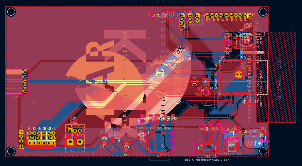
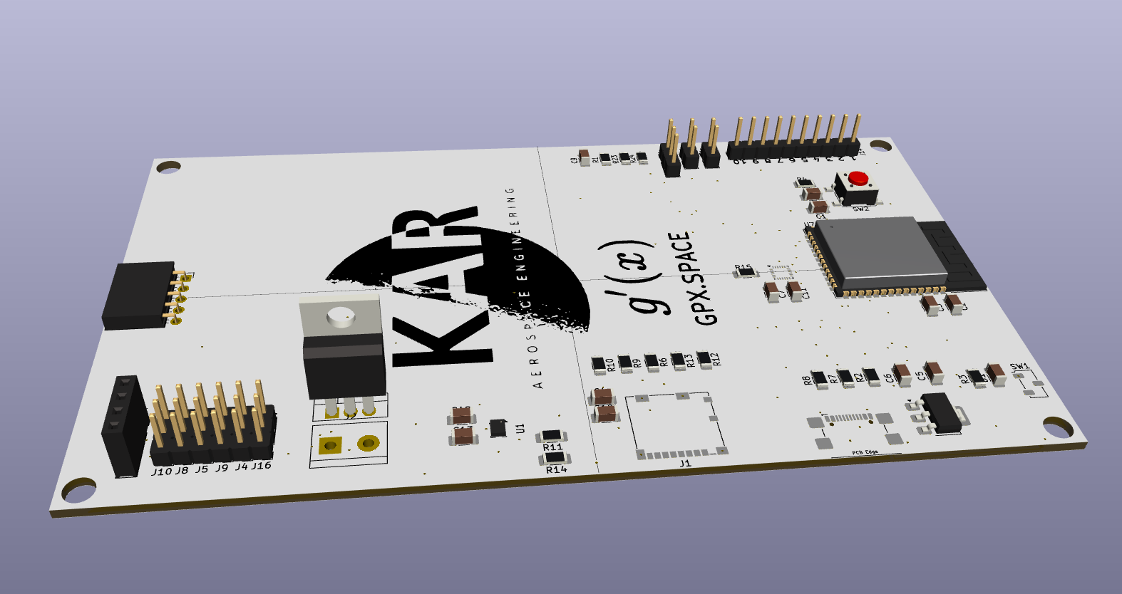
AviCDEsp32 is an open-source printed circuit board by kimsj5025, from the kimsj5025/AviCDEsp32 repository on GitHub. It is a 2-layer board of 140 × 80 mm with 59 parts on 80 nets, routed with 533 tracks and 128 vias.
It is built around the ESP32-S3-WROOM-1-N8, BMP280 and AMS1117-3.3, with the IRLZ44N among its other parts. Its parts include 17 resistors, 15 connectors, 13 capacitors, 4 ICs and 2 switches. It belongs with the ESP32 boards of this library.


https://youtu.be/nyiRkpx4r_E?si=UPnUjiUW3JROnrmD
이번에는 아두이노에 사용되는 Atmega328p가 아니라 Esp32 S3 wroom 1 모듈을 사용하였다.
주요 사양으로는
이 중에서 가장 마음에 들었던 것은 wifi를 지원한다는 것이다. 이를 이용해서 더 좋은 UI를 통해 기타 핀들을 제어할 수 있는 발판을 만들었다.
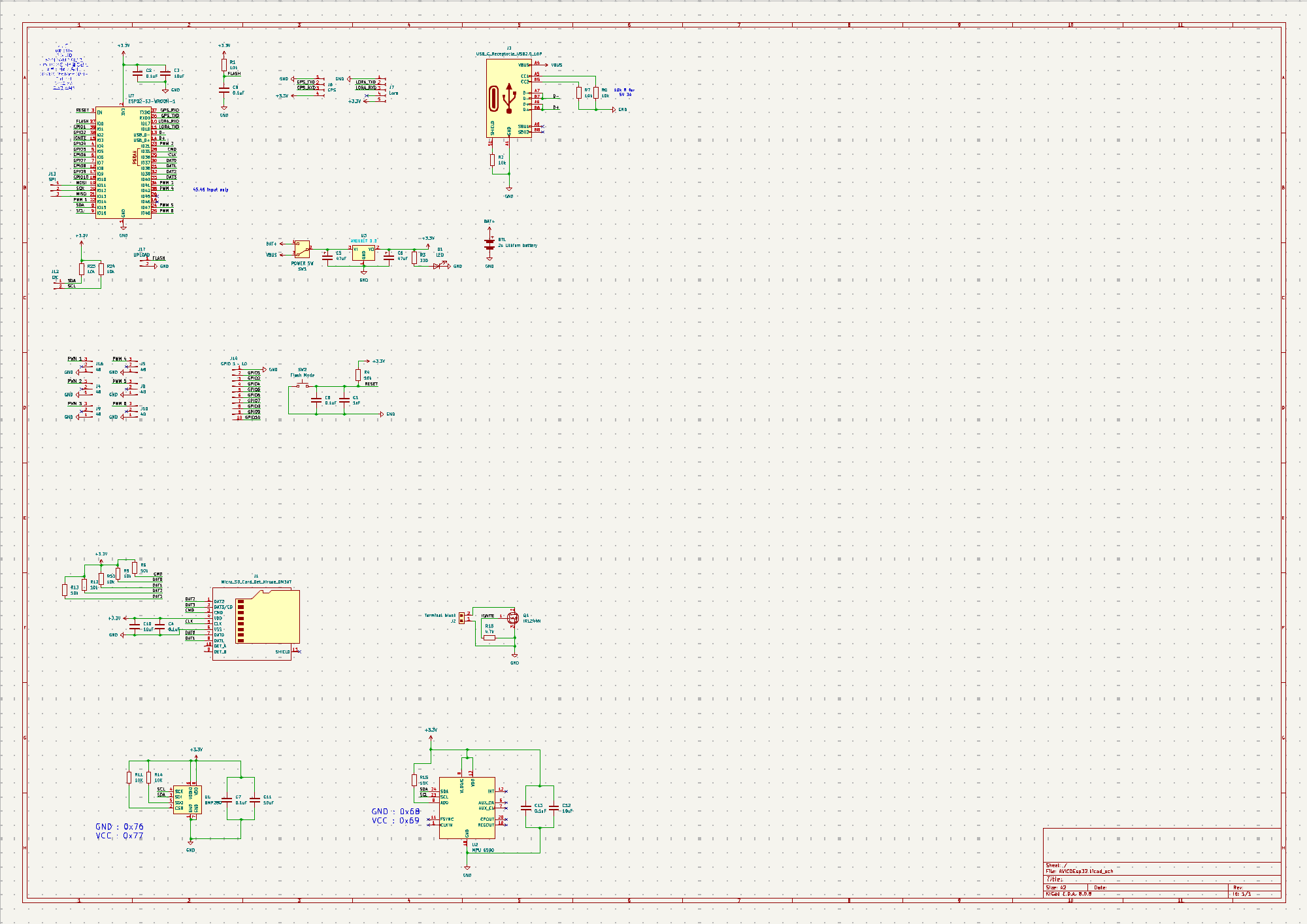
가속도계는 TDK InvenSense사의 mpu6500 6축 가속도 센서를 사용하였다. 이 센서는 최대 16g까지 측정할 수 있으며, 해상도는 16bit이다. 흔히 아두이노용 가속도계로 알려진 mpu6050의 상위 버젼 가속도계이다. 데이터시트의 Typical Operating Circuit을 보고 I2C용으로 배선하여 값을 읽을 수 있도록 하였다.
기압계는 Bosch Sensortec GmbH사의 bmp280을 사용하였다. 이것 또한 아두이노용 기압계로 잘 알려져 있는 bmp180의 상위 모델로, bmp180보다 더 좋은 성능을 가지고 있다.
이 모듈의 분해능은 ±0.12 hPa로, 약 ±1 m 정도의 높이를 측정할 수 있다. 우리가 목표하고 있는 고도가 약 400m이기 때문에 1m의 분해능은 약간 아쉬운 수준이긴 하지만 그래도 못 쓸 정도는 아니다.
저번에는 SD카드를 SPI로 읽었지만 이번에는 esp32의 SDMMC 기능을 사용하여 읽어 보려고 하였다. 이를 위해서 각 데이터 라인에 10k옴의 풀업 저항을 배치하였고 그 결과 SD카드를 읽고 쓸 수 있게 되었다.
저번과 똑같이 IRLZ44N과 터미널 블럭을 이용해 만들어 주었다.
센서와 MPU등 보드에 있는 부품들의 전원을 공급하기 위해 AMS1117-3.3을 사용하였다.
가속도계와 기압계의 구동 전압이 3.3V이기 때문에 4.8~18V까지 입력을 받아서 3.3V로 출력하는 이 칩을 사용하여 최대 2.5A까지 출력이 가능하도록 하였다.
또한 굉장히 저렴하기 때문에 대량생산시에 유리하다.
다만 전압 강하가 1.2V로 상당히 큰 편이기 때문에 최소 4.5V 이상의 전원을 인가해야 한다는 단점이 있다. 때문에 배터리와 usb사이의 정류 회로를 구동시 500mV 이하의 전압 강하를 갖는 다이오드를 사용해야 한다.
저번에는 전원을 넣었을 때 이게 켜져있는지 꺼져있는지 구별하기 어려웠는데, 이번에는 AMS1117에서 나오는 3.3V라인에 LED를 배치하여 보드의 3.3V라인에 전원이 들어오고 있는지 아닌지를 한눈에 알 수 있도록 하였다.
ESP32 s3는 풀 스피드 USB2.0를 지원하고 내장 CDC가 있기 때문에 D- D+핀만 정상적으로 연결해 준다면 usb를 이용하여 코딩과 시리얼 모니터(UART0)를 볼 수 있다. 또한 USB에서 나오는 5V전원을 통해 보드 전체의 전원이 들어올 수 있도록 해 주었다. 이를 통해 기존 코드 업로드 방식에서 엄청난 혁신을 이루었는데, 코드를 업로드 할 때마다 리셋 버튼을 누르는 수고와 항상 USB TTL컨버터를 찾아야 하는 번거로움에서 해방되었다. (그래서 USB TTL컨버터를 잃어버렸다;)
기존에 기타 모듈과 PWM을 위한 핀 몇개만 빼 두었었는데, 이번에는 I2C, SPI뿐 아니라 서로다른 10개의 GPIO에 바로 접근할 수 있도록 외부 헤더핀을 배치하였다. 이를 통해 예상치 못한 GPIO단자가 필요할 경우에 사용할 수 있도록 하였다.
https://github.com/kimsj5025/AviCDEsp32
https://github.com/kimsj5025/AViCDEsp32-for-TMS
아래는 이를 실제로 사용한 사례이다.
| Qty | Value | Footprint | References |
|---|---|---|---|
| 12 | 10k | Resistor_SMD:R_1206_3216Metric | R1, R2, R4, R6, R7, R8, R9, R10, R12, R13, R23, R24 |
| 6 | 0.1uF | Capacitor_SMD:C_1206_3216Metric | C2, C4, C7, C8, C9, C13 |
| 6 | 48 | Connector_PinHeader_2.54mm:PinHeader_1x03_P2.54mm_Vertical | J4, J5, J8, J9, J10, J16 |
| 4 | 10uF | Capacitor_SMD:C_1206_3216Metric | C3, C10, C11, C12 |
| 4 | LOGO | LOGO | G***, G***, G***, G*** |
| 3 | 10K | Resistor_SMD:R_1206_3216Metric_Pad1.30x1.75mm_HandSolder | R11, R14, R15 |
| 2 | 47uF | Capacitor_SMD:C_1206_3216Metric | C5, C6 |
| 1 | 1uF | Capacitor_SMD:C_1206_3216Metric | C1 |
| 1 | 330 | Resistor_SMD:R_1206_3216Metric | R3 |
| 1 | 4.7k | Resistor_SMD:R_1206_3216Metric | R16 |
| 1 | AMS1117-3.3 | Package_TO_SOT_SMD:SOT-223-3_TabPin2 | U3 |
| 1 | BMP280 | Package_LGA:Bosch_LGA-8_2x2.5mm_P0.65mm_ClockwisePinNumbering | U1 |
| 1 | ESP32-S3-WROOM-1 | RF_Module:ESP32-S3-WROOM-1 | U7 |
| 1 | Flash Mode | Button_Switch_SMD:SW_SPST_PTS645 | SW2 |
| 1 | GPIO 1 ~ 10 | Connector_PinHeader_2.54mm:PinHeader_1x10_P2.54mm_Vertical | J14 |
| 1 | GPS | Connector_PinSocket_2.54mm:PinSocket_1x04_P2.54mm_Vertical | J6 |
| 1 | I2C | Connector_PinHeader_2.54mm:PinHeader_1x02_P2.54mm_Vertical | J12 |
| 1 | IRLZ44N | Package_TO_SOT_THT:TO-220-3_Vertical | Q1 |
| 1 | LED | Capacitor_SMD:C_1206_3216Metric | D1 |
| 1 | Lora | Connector_PinSocket_2.54mm:PinSocket_1x05_P2.54mm_Horizontal | J7 |
| 1 | MPU 6500 | Sensor_Motion:InvenSense_QFN-24_3x3mm_P0.4mm | U2 |
| 1 | Micro_SD_Card_Det_Hirose_DM3AT | Connector_Card:microSD_HC_Molex_104031-0811 | J1 |
| 1 | POWER SW | Button_Switch_SMD:Nidec_Copal_CAS-120A | SW1 |
| 1 | SPI | Connector_PinHeader_2.54mm:PinHeader_1x03_P2.54mm_Vertical | J13 |
| 1 | Terminal block | TerminalBlock:TerminalBlock_bornier-2_P5.08mm | J2 |
| 1 | UPLOAD | Connector_PinHeader_2.54mm:PinHeader_1x02_P2.54mm_Vertical | J17 |
| 1 | USB_C_Receptacle_USB2.0_16P | Connector_USB:USB_C_Receptacle_GCT_USB4110 | J3 |
The 57 most common of 59 parts.
Churrosoft/OpenEFI-PCB
Coleccion de PCB y planos recomendados para montar una OpenEFI


anshukumar146/GitHub
A compact, self-contained development board for the 8051 microcontroller family (AT89x51xxP), designed in KiCad — built to run 8051 firmware on the bench with nothing more than a barrel-jack power supply and a…

FREILab/easyVerwaltungHardware
Hardware und Firmware für alle Geräte im Bezug zu easyVerwaltung


Pingu207/ROCKET
Designing and building a TVC rocket controlled by a custom PCB wired to a ESP32-WROOM board

alexander-armitage/AURA-Hardware
AURA is a set of modular PCBs designed in KiCad for versatile robotics and aerospace applications — from drones and quadrupeds to rockets.

Gupatron/Gupsfirstpcb
This is the first pcb that I will manufacture and intend to use for teleop usecases in my personal projects.
It measures 140 × 80 mm and has 2 copper layers, 1.6 mm thick.
59 parts, built around the ESP32-S3-WROOM-1-N8, BMP280, AMS1117-3.3 and IRLZ44N. The full list of its parts is on this page, with links to each part's symbol and footprint where PCBKit's library has them.
From the kimsj5025/AviCDEsp32 repository on GitHub, at the commit this page was made from: the board is AViCDEsp32.kicad_pcb and its schematic AViCDEsp32.kicad_sch. PCBKit opens the board in the browser, with nothing to install.
Its repository states no licence, so its author keeps all rights: ask kimsj5025 before reusing the design.