2 layers60 × 30 mm
Controller
google/mozc-devices
Circuit diagrams and firmware source code for Gboard DIY keyboards
11 parts3kApache-2.0

 kiall/arcade-coinmech-interface2
Arcade Coin Mechanism Interface Board
CoinMechInterface is an open-source printed circuit board by kiall, from the kiall/arcade-coinmech-interface repository on GitHub, published under the Apache-2.0 licence. It is a 2-layer board of 50 × 30 mm with 11 parts on 5 nets, routed with 55 tracks and 0 vias.
Its parts include 5 connectors and 2 diodes. It belongs with the retro computing and games and interfaces and adapters boards of this library.
This is a simple little interface board to connect a 12V arcade coin mechanism to a 5V interface board (e.g. the Ultimarc I-Pac). The board supports connecting 2x 12V coin mechanism, and 1x 12V Coin Counter.
I don't sell these! The design is Open Source. I upload my designs to OSH Park and have them manafacture the board for me, I've included a link below.

(I do not earn commission etc from OSH Park if you order from them)
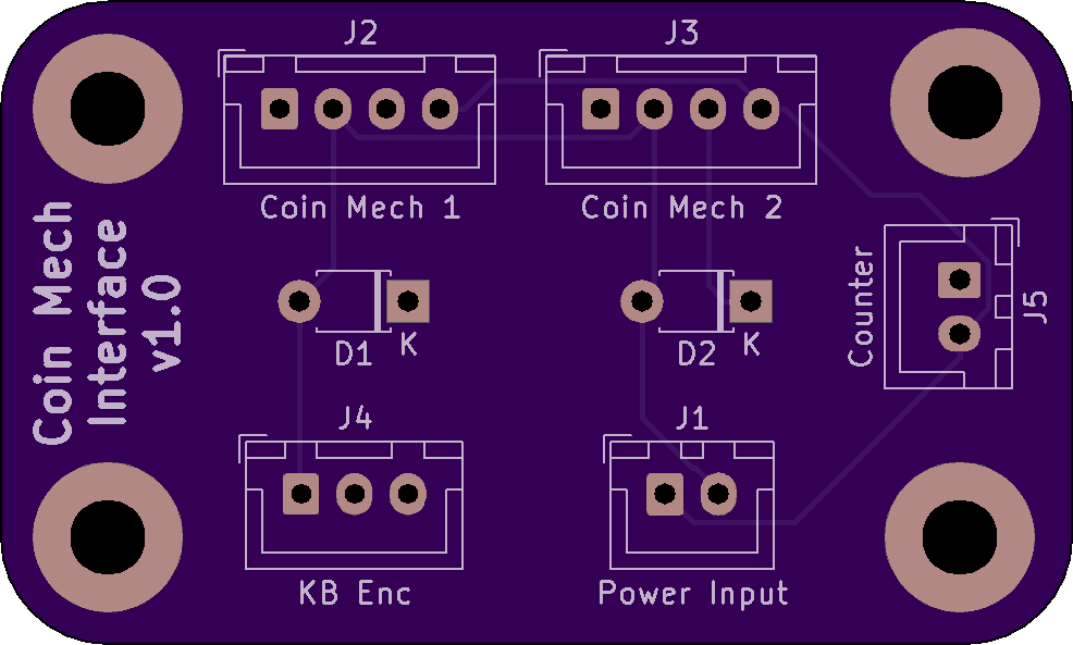
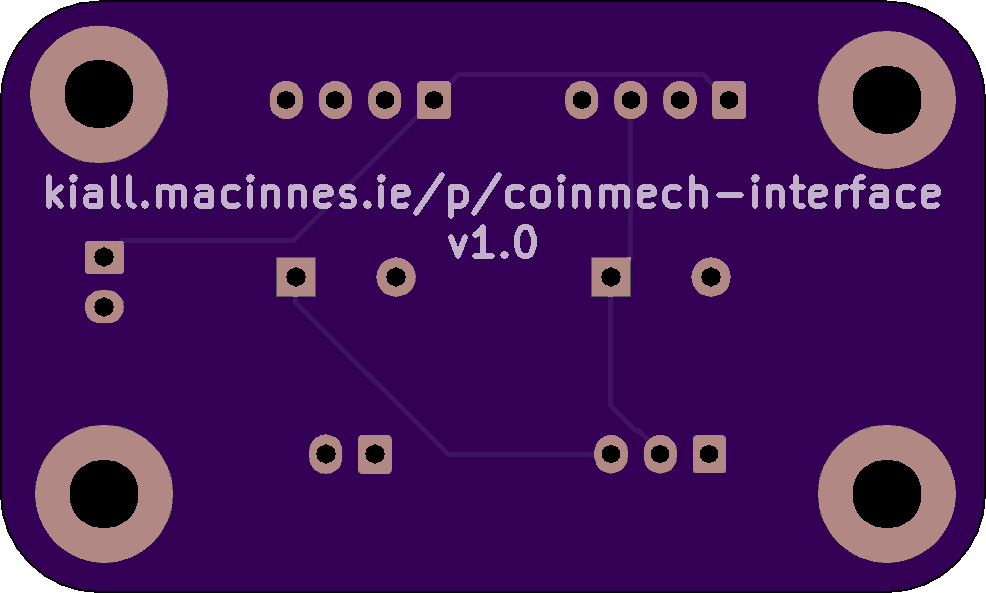
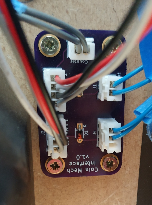
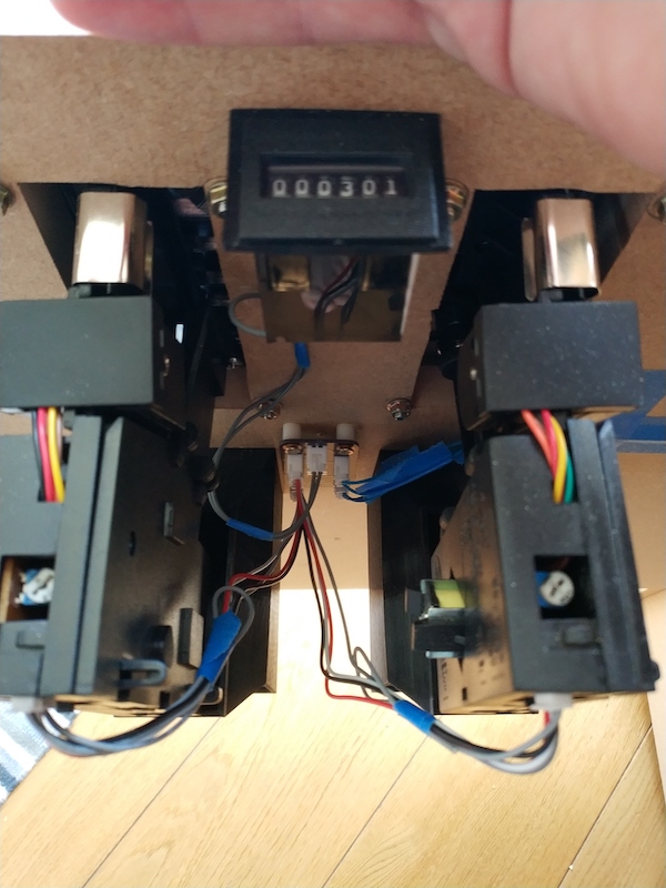
I use JST-XH sockets everywhere, but any socket with a 2.54mm pitch and approximatly the same outside will do just fine.
Generally, the wires on a coin counter are identical and it doesn't actually matter which way around you wire them.
| Qty | Value | Footprint | References |
|---|---|---|---|
| 1 | Coin 1 Zener | Diode_THT:D_T-1_P5.08mm_Horizontal | D1 |
| 1 | Coin 2 Zener | Diode_THT:D_T-1_P5.08mm_Horizontal | D2 |
| 1 | Coin Mech 1 | Connector_JST:JST_XH_B04B-XH-A_1x04_P2.50mm_Vertical | J2 |
| 1 | Coin Mech 2 | Connector_JST:JST_XH_B04B-XH-A_1x04_P2.50mm_Vertical | J3 |
| 1 | Counter | Connector_JST:JST_XH_B02B-XH-A_1x02_P2.50mm_Vertical | J5 |
| 1 | KB Enc | Connector_JST:JST_XH_B03B-XH-A_1x03_P2.50mm_Vertical | J4 |
| 1 | Power Input | Connector_JST:JST_XH_B02B-XH-A_1x02_P2.50mm_Vertical | J1 |
The 7 most common of 11 parts.
It measures 50 × 30 mm and has 2 copper layers, 1.6 mm thick.
11 parts. The full list of its parts is on this page, with links to each part's symbol and footprint where PCBKit's library has them.
From the kiall/arcade-coinmech-interface repository on GitHub, at the commit this page was made from: the board is kicad/CoinMechInterface.kicad_pcb. PCBKit opens the board in the browser, with nothing to install.
Its repository publishes it under the Apache-2.0 licence: you may reuse it on that licence's terms (keep the author's notice, and for a copyleft licence share your changes alike).
google/mozc-devices
Circuit diagrams and firmware source code for Gboard DIY keyboards


FrameworkComputer/ExpansionCards
Reference designs and documentation to create Expansion Cards for the Framework Laptop

hoglet67/RGBtoHDMI
Bare-metal Raspberry Pi project that provides pixel-perfect sampling of Retro Computer RGB/YUV video and conversion to HDMI

hackclub/OnBoard
💡 Join 1,000 teenagers and make your first PCB with a $100 grant!


tardate/LittleArduinoProjects
a collection of "Little Electronic & Arduino Projects", most involving electronics or an Arduino in one way or another!

basilfx/TRADFRI-Hacking
Hacking IKEA TRÅDFRI products, such as light bulbs, window blinds and other accessories.